Forward-wave enhanced radiation in the terahertz electron cyclotron maser
2022-12-28ZiChaoGao高子超ChaoHaiDu杜朝海FanHongLi李繁弘ZiWenZhang张子文SiQiLi李思琦andPuKunLiu刘濮鲲
Zi-Chao Gao(高子超), Chao-Hai Du(杜朝海), Fan-Hong Li(李繁弘), Zi-Wen Zhang(张子文),Si-Qi Li(李思琦), and Pu-Kun Liu(刘濮鲲)
School of Electronics,Peking University,Beijing 100871,China
Keywords: electron cyclotron maser,ohmic loss,harmonic operation,traveling wave interaction
1. Introduction
The terahertz (THz) wave sources are mainly composed of two families, i.e., the optical sources and the electronic sources. Gyrotron is one of the electronic devices operating based on the principle of electron cyclotron maser(ECM)which can generate coherent THz radiation from watts to megawatts level.Recently,gyrotrons have achieved significant advancements from sub-THz to THz range and find use in numerous applications, including biomedicine, security, plasma heating, etc.[1–9]Unfortunately, due to the skin effect of the limited conductivity,gyrotrons suffer from severe ohmic dissipation in such a high-frequency band. In the THz gyrotron experiment proposed in Ref.[4],a high electron efficiency(about 10%) was predicted by simulation, whereas the ohmic losses decrease the output efficiency down to 1.3%.
In the gyrotron-devices, the electromagnetic (EM) wave is excited by the energetic helical electron beam based on the instability of ECM.[10]An open cavity with a cutoff entrance,a uniform section, and an output taper is a typical electronwave interaction circuit for the gyrotron oscillators. Such a circuit is characterized roughly by its diffraction quality factorQdand ohmic-loss quality factorQohm,and theseQ-values are defined as follows:))
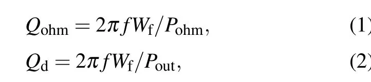
wherefis the operating frequency,Wfis the total wave energy inside the cavity,PohmandPoutare the dissipated and output power,respectively. In this case,the totalQvalue is given by
Qtotal=2π fWf/(Pout+Pohm)=QdQohm/(Qd+Qohm).(3)The proportion of ohmic losses power to the total power is expressed as

For theQdvalue, a spectral analysis of the resonant width yields[11]

whereΓis the reflection coefficient at the output horn,lis the axial mode index,Lis the cavity length,andcis the light speed. Meanwhile,the ohmic factor is given by[12]

whererwis the cavity radius,σis the conductivity of the cavity wall,µis the permeability, andχmnis the eigenvalue of TEmnmode. According to Eq. (4), in previous work dealing with ohmic losses problems,researchers concentrated mainly on how to reduce theQdvalues or increase theQohmvalues.A natural solution to this problem is to use a highly oversized cavity with a large radiusrw[4,13,14]to reduce theQohm.This solution is widely used in gyrotrons designed for applications of fusion plasma heating.[15–17]However, in such an overmoded cavity,the mode spectrum is dense,thereby complicating the mode competition and making the excitation of operating mode especially tough at the cyclotron harmonic operation.[18]Another simple solution is to shorten the circuit lengthLto reduce theQdvalue. However,this solution necessitates a large beam current.Thus,in some applications that do not require a high output power,the beam current is small and not qualified for the wave excitation threshold in a shortened cavity. Moreover,using various types of cavities,such as sectioned cavities,[19–22]cavities with axial irregularities,[23,24]or tapered cavities,[25,26]is demonstrated to be able to reduce theQdvalue effectively.
In this work, we propose and stress the advantageous function played by the forward wave component in a highharmonic gyrotron oscillator and give a detailed look into the high-order-axial-mode (HOAM) traveling-wave interaction. The work is a more detailed and accurate version of the previous preprinted work submitted to arXiv in April 2021.[27]Two critical problems are specially studied in this work. First,the excitation of HOAMs is naturally unstable owing to the competition from the first axial mode.[28]Second, owing to the weak coupling between the HOAMs and electrons,the total electron efficiency is generally small. Investigation in this paper reveals that a short lossy section loaded in the cavity will effectively stabilize the oscillation of HOAMs, and the magnetic field profile with a down-tapered tail can provide an efficient forward-wave enhancement owing to traveling-wave amplification.
The context is organized as follows. Section 2 elaborates the ohmic-loss problem in the terahertz regime and investigates the performance of different axial modes based on selfconsistent steady-state calculation. Section 3 presents a general approach to excite the HOAMs stably. Section 4 proposes a scheme to enhance the electron efficiency of HOAMs based on traveling wave interaction. Sections 5 and 6 present some discussions and conclusions,respectively.
2. Performance of different axial modes
2.1. Ohmic losses in the terahertz range


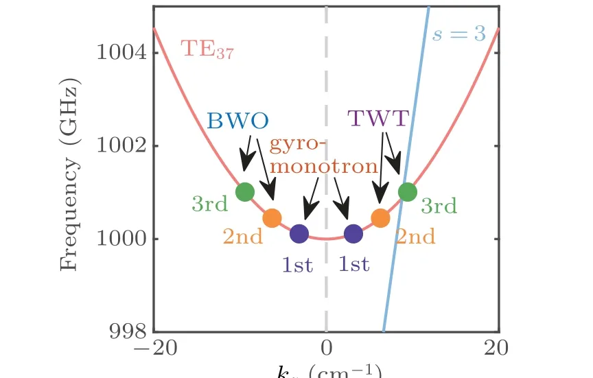
Fig.1. Dispersion diagram of the gyro-BWO,gyrotron,and gyro-TWT regime. Here,1st,2nd,and 3rd correspond to the first,second,and third axial mode.

Fig.2. Axial field profile of different axial modes in the(a)gyro-TWT and(b)gyro-BWO regimes.
2.2. Steady-state calculation of HOAMs
In our investigation,a 1 THz third harmonic gyrotron operating at TE37mode is considered,and all electrons describe helical trajectories with the axes coinciding with the cavity axis. The accelerating voltage is 80 kV, the beam current is 0.7 A,and the pitch factor of electrons is 1.5.The cavity length is 7.2 mm. Experimental research based on similar parameters has been presented in Ref.[4],where a high electron efficiency(around 10%)was predicted by simulation,whereas the ohmic losses decrease the total efficiency down to 1.3%. The large proportion of losses was induced by a long cavity.
Here, the axial eigenmodes inside the resonant structure are investigated. For a gyrotron system with given operating parameters(voltage,magnetic field strength,current,etc.),there are several possible axial resonant states determined by the cavity structure. The oscillation power is extracted by either one or simultaneously by some of those states.Frequency-domain nonlinear theory(see Appendix A)is used to predict the possible steady states of a gyrotron circuit. In our consideration,the resistivity of the cavity wall is assumed to equal five times that of pure copper(5ρcu). Under this condition, theQvalues of different axial modes are presented in Table 1,where theQdof the first-order axial mode(FOAM)is far larger than theQohm,and the HOAMs operation decreases theQdvalues greatly. The field profiles are correspondingly shown in Fig.2. The field peak of FOAM locates at the middle of the cavity where the wave is mainly amplified;by contrast,the field peaks of second or third axial modes move backward, thereby the ohmic heating mostly occurs at the rear of the cavity [see Figs. 3(b) and 3(c)]. In this way, the share of ohmic losses(ηohm/ηe)greatly decreases. Here, the electron efficiencyηe, the ohmic loss efficiencyηohm, and the output efficiencyηware defined asηe=Pe/UI=(Pout+Pohm)/UI,ηohm=Pohm/UI,ηw=Pout/UI,respectively,wherePeis the total field power extracted from the electrons,Poutis the output power,Pohmis the ohmic loss power,Uis the accelerating voltage, andIis the beam current. Take the results shown in Fig. 3 as an example, theηohm/ηevalue of the first, second,and third axial modes are 80.43%, 47.14%, and 21.92%, respectively. The final output performances of the first and second axial modes are illustrated in Fig. 4. It is shown that theηohm/ηevalue of the FOAM is larger than 80%, whereas the second-order axial mode(SOAM)operation decreases it down to at most 48%.However,as shown in Fig.4(a),despite the decreased losses,the final output efficiency of SOAM is similar to(or slightly exceeds)that of FOAM.This is can be explained as follows: first, theQvalue of SOAM is much smaller than that of the FOAM, the electron-wave coupling of the SOAM is weaker than that of the FOAM; second, both forward and backward waves are tightly coupled to the wave for FOAM interaction, while for the HOAMs, forward wave participates mainly in the interaction. Owing to the above reasons, the electron efficiency of SOAM is deteriorated [see the dashed lines shown in Fig.4(a)].

Table 1. Q values of different axial modes.

Fig.4. (a)Output efficiency and electron efficiency(ηe)of the first and second axial modes. (b) Share of ohmic losses (ηohm/ηe) of the first and second axial modes. The beam current is 0.7 A.
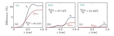
Fig. 3. Electron efficiencies and ohmic loss efficiencies of (a) the first, (b) second, and (c) third axial modes. The magnetic field strength is 13.64 T,and the beam current is 0.7 A.
3. Axial modes competition
Using the steady-state simulation, the performances of possible axial modes is investigated in Section 2. In practice,the electrons and the resonate structure will select their favored state and give out energy, meaning that some of the possible axial modes are unstable during their excitation. Considering that the FOAM normally possesses stronger coupling strength with the electrons than HOAMs owing to its highQ-value,the generation of higher modes is generally hard. In Ref.[34], it is demonstrated that this situation can be changed when the electron accelerating voltage is low and the resonate cavity is long. In Refs.[35,36]short irregularity of cavity radius helps shape the axial profile into higher order, which also provides an excitation scheme for HOAMs. However,such irregularity has a great probability to bring in extra axial modes, thereby complicating the competition situation.
Here,a more general approach is adopted to alleviate the mode competition. The cavity structure with a short lossy belt is presented in Fig. 5(a). The authors would like to mention that the concept of using a lossy section in gyro-oscillators was first proposed by Bandurkinet al.[35,37]The modeling methods of the lossy part are detailed in Appendix B. The lossy section whose effective resistivity isρprovides additional losses only for the FOAM,whereas for HOAMs whose field strength is weak in this section, the oscillation is almost undisturbed.The start oscillation currents(SOC)are shown in Fig.5(b). In a normal configuration with an effective resistivityρ=5ρcu,the first axial mode possesses the lowest start oscillation current over a wide range.By loading a lossy section(assume that the lossy section is 3 mm in length),the SOC of the FOAM increases rapidly in the low-magnetic-field range. By contrast,the SOC of the SOAM remains nearly unchanged. As a result,the excitation region of HOAMs is greatly extended. Note that in our case, the excitation region of the third axial mode is relatively narrow, and its SOC is relatively high, we mainly investigate the excitation scenario of the SOAM in the following analysis.
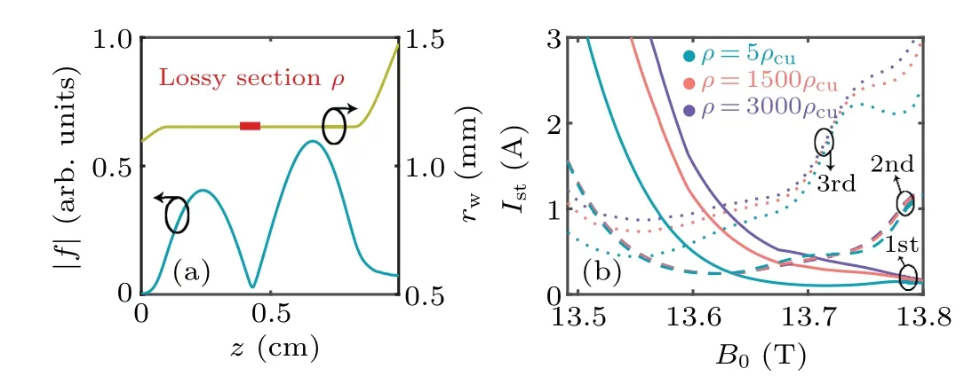
Fig. 5. (a) Structure of cavity (the right y-axis) with a lossy section whose effective resistivity is ρ,and the axial field profile of the SOAM(the left y-axis). (b)Start oscillation currents of different axial modes.
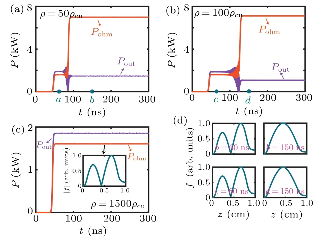
Fig. 6. Output and loss power of the interaction systems shown in Fig. 5(a) with different effective resistivities: (a) ρ =5ρcu, (b) ρ =100ρcu,(c)ρ=1500ρcu. The inset shows the field profile after the system reaches stable. (d) The axial field profiles at times marked in (a)and(b). The magnetic field is 13.62 T,and the beam current is 0.7 A.
Time-domain simulation is utilized to further verify the competition situation. From the output power shown in Fig.6(a),for a cavity with homogeneous resistivity,the SOAM will be first excited and then suppressed rapidly by the FOAM.It is likely that the SOAM excited first induces an electron bunching which is also suitable for the FOAM, thereby assisting the excitation of FOAM.When a section of weak loss[ρ=100ρcu,see Fig.6(b)]is loaded,the oscillation of SOAM becomes relatively stable and maintains a longer time after excitation. Nevertheless, the SOAM will also be suppressed in long-time interaction. When stronger loss [ρ=1500ρcu, see Fig.6(c)]is loaded,the SOAM will succeed in the mode competition with the FOAM and extract energy from the electrons steadily.
To conclude, a short lossy section at the middle of the cavity increases the excitation threshold current of the FOAM without affecting the SOAM,thereby helping suppress the excitation of FOAM and stabilize the oscillation of SOAM.
4. Forward wave amplification
From the analysis in Section 2, despite the decreased share of ohmic losses of HOAM interaction, the electron efficiencies of HOAMs are smaller than that of FOAM, thus the final output power of the HOAMs is similar to that of the FOAM.In this section,we propose an approach to partly solve this problem. For the case of HOAMs interaction,the forward wave participates mainly in the interaction. Thus, enhancing the efficiency of the forward wave is a rational way to compensate for the efficiency deterioration of HOAMs.
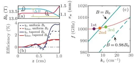
Fig. 7. (a) Cavity configuration with inhomogeneous magnetic field profile. (b)The electron efficiencies and ohmic losses of the second axial modes under different magnetic field profiles.The magnetic strength at the uniform section is 13.62 T,and the beam current is 1 A.(c)Dispersion diagram of different magnetic field strengths. The straight lines indicate synchronization lines.
A down-tapered magnetostatic field has been demonstrated to be beneficial for the forward wave interaction.[38,39]Note that the energy extracting process mainly concentrates at the rear of the cavity for HOAM interaction, a magnetic profile with a tapered tail is adopted in our study. The magnetic field profile composed of two parts,i.e.,an upstream uniform section and a downstream taper,is shown in Fig.7(a).The uniform part aims to ensure the excitation of the desired mode and lock the bunching phase of electrons at a certain frequency;after that, the excited wave is amplified through the tapered magnetic field profile. From the dispersion diagram shown in Fig. 7(c), the reduction of magnetic field strength leads to a downward translation of the synchronization line,which converts the operation region into a deep gyro-TWT regime. As shown by the blue solid line in Fig.7(b),the electron efficiency is greatly enhanced by the tapered magnetic field profile owing to the forward-wave amplification; meanwhile,by comparing the red solid line with the red dashed line,the ohmic loss efficiency stays nearly unchanged after the nonuniform magnetic field profile is adopted.
The increment of electron efficiency is demonstrated to greatly depend on the gradient of magnetic field profile, and the results are illustrated in Fig. 8. When the gradient is too large, the electron-wave mismatch will be increased, leading to a decoupling of the electrons and the wave, and thus the electron efficiency is decreasd. Therefore, to achieve optimized output performance, a proper gradient should be selected. In our investigation, when ∆B/Bis around 2%–6%,the output efficiency of the SOAM is nearly twice as much as that of the FOAM [see Fig. 8(a)]. In addition, the utilization of the nonuniform magnetic field can further reduce the ohmic losses,and the final ratio of the ohmic losses efficiency to the electron efficiency can be less than 40%[see Fig.8(b)].Although the forward wave gains more energy in the tapered magnetic field case,the dissipated power is nearly the same as the uniform magnetic field case and thereby theηohm/ηevalue is reduced, because the power flow is compressed to the end of the cavity.
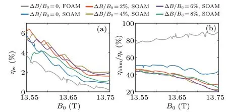
Fig. 8. (a) Output efficiency and (b) share of ohmic losses of the first and second axial modes with different magnetic field gradients. The effective resistivity of the lossy belt is ρ =1500ρcu in the SOAM interaction.
5. Discussion
In the terahertz range,the effective resistivity mentioned in this work can be adjusted by intendedly increasing the material surface roughness,[40,41]or using nanopowder mixture BeO–TiO2–W,where BeO is for beryllium oxide,TiO2for titanium dioxide,and W for tungsten.[42]There are two prominent advantages of using a lossy section compared with changing the cavity radius. First, the lossy section will not introduce extra axial-eigenmodes of the resonant structure,thereby simplifying the competition situation. Second,as is shown in Fig.9,theηohm/ηevalue of SOAM is insensitive to the effective resistivity of the lossy section.
This paper focuses on the discussion of two physical problems,namely,the stable excitation and the forward-wave enhancement of the HOAMs in the gyro-TWT regime of a THz gyrotron oscillator. Design of a reliable interaction circuit for engineering applications still needs more considerations,such as the competition between waveguide modes,the velocity spread of the electrons,etc. These practical considerations are beyond the scope of this paper and will be discussed in deep in future work.

Fig.9. The ηohm/ηe value of the SOAM versus the effective resistivity of the lossy section. The magnetic field strength is B0 =13.64 T, and the beam current is 0.7 A.
6. Conclusion
Aiming to reduce the ohmic dissipation in the ECM,the proposal of traveling-wave interaction is systematically investigated in this paper. Unlike the conventional gyromonotron operation with a high-Qresonant mode, i.e., FOAM, we attempt to excite low-QHOAMs and constitute a forward-wave amplification interaction. Therefore, two physical problems existing in the HOAMs operation are solved theoretically.First, the excitation of HOAMs is unstable and encounters competition from FOAM.It is proved that a short lossy section in front of the cavity will greatly raise the oscillation threshold of FOAM without disturbing the HOAMs. Second, owing to the weak coupling between the electrons and HOAMs,the electron efficiencies of HOAMs are lower than those of FOAM. Through a nonuniform magnetic field profile with a down-tapered tail, the forward wave is amplified in the deep TWT regime,thereby enhancing the electron efficiency. In the 1 THz gyrotron operating at the third harmonic,the final output efficiency of the SOAM is nearly twice as much as that of the FOAM, and the ohmic loss power only accounts for less than 40%of the total extracted power. The scheme proposed in this work provides a possible way for further developing the low-loss continuous-wave THz gyrotron.
Appendix A:Self-consistent nonlinear theory
First, the nonlinear theory in the frequency domain is presented as follows. Based on the assumption of steady single-mode operation,the electron-wave interaction equation is given by[43,44]
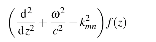
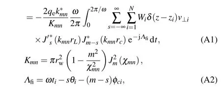
wheref(z) is the axial field profile,rwis the cavity radius,χmnis the eigenvalue of TEmnmode,Nis the numbers of the macroparticles,sis the harmonic number,qe,zi,Wi, andv⊥iare the charge,transient position,weight factor,and transverse velocity of each macroparticle,rcandΦcare the electron guiding center and guiding center angle,rLandθare the Larmor radius and transient angle in guiding center coordinate. Obviously, different values ofm,n, andswill result in different modes interacting with different harmonics. On the other hand,the self-consistent electron dynamics equations are given by[44]
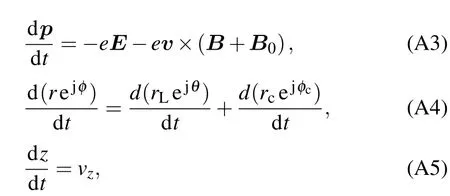
wherepis the momentum of electrons,E,BandB0are the EM electric field,EM magnetic field,and static magnetic field,respectively,andvzis the axial component of the electron velocity. Generally,the field profilef(z)is expressed as the superposition of forward and backward wave
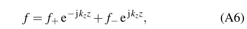
wheref+andf−are the forward wave and backward wave components, respectively. The outgoing boundary conditions are implemented for the calculation of gyrotron oscillators.[45,46]In this way, at the cavity upstream cutoff(z=0), the wave is pure backward component(f+=0), and at the cavity exit(z=L,whereLis the total length of the simulated area), the wave is pure forward component (f−=0).Namely,

Together with Eqs. (A3)–(A5), the oscillation is generated from noise level to a specific eigenstate, and the calculation is operated using the FDTD algorithm. In order to reduce the boundary reflection, perfect-matched layers are loaded at both ends of the cavity to approximate the outgoing-wave boundary.[43]
In a word,the frequency-domain code is effective for the prediction of possible steady states of a single mode,while the time-domain code is capable of simulating the start-oscillation scenario of multimode interaction. Both methods were verified in a series of previous publications.[47–49]
Appendix B: Modeling of effective resistivity of metallic wall
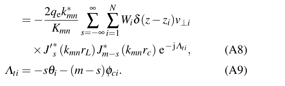
In our methodology, the effective resistivity is implemented by the modification of the transverse wave number,and the expression is given by[50,51]
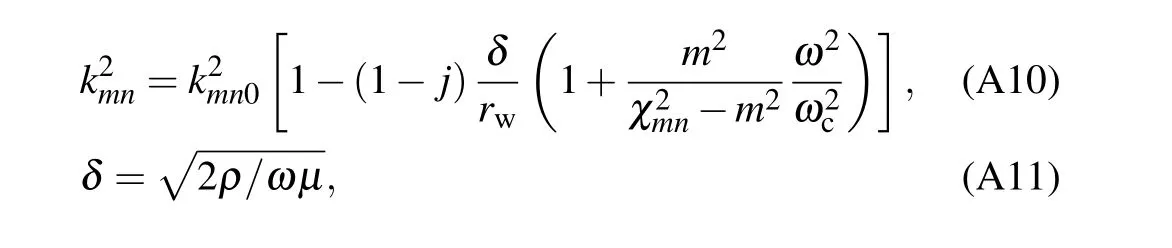
wherekmnis the first-order perturbation transverse wave number, andkmnrepresents the unperturbed value which is expressed askmn=χmn/rw,δandωcare skin depth and cutoff angular frequency, respectively. Substituting Eq. (A10)into the left-hand side of Eq.(A1),the metallic wall resistivity is considered self-consistently. To realized the simulation of partly-loaded losses,the effective resistivityρin Eq.(A11)is replaced as a function of the axial coordinate. Since the axial wavenumber alters with the cavity resistivity,the reflection induced by the mismatch of the axial wavenumber can be selfconsistently considered in the simulation.
Note that in the time-domain simulation, the concept of frequency in Eq. (A10) is invalid, and the expression cannot be substituted into Eq. (A8) directly. In this case, we utilize two algorithms to solve this problem in the time-domain simulation.

The first method is to approximate the operating frequencyωas the constant valueωc,[52]In the gyrotron case,considering that the operating frequency is usually near-cutoff,the approximation does not introduce a large deviation.
The second one is to use a recursive algorithm to calculate the convolution introduced from Fourier’s transform. The expression ofkmnin Eq.(A10)is rewritten as

where the asterisk represents convolution. Using a recursive algorithm presented in Ref.[52],the convolution in Eq.(A15)is calculated efficiently. Both algorithms are demonstrated to exhibit high precision.[52]
Acknowledgements
This work was supported in part by Beijing Science Foundation for Distinguished Young Scholars (Grant No.JQ21011),the National Natural Science Foundation of China(Grant Nos. U1830201 and 61531002), and Newton Advanced Fellowship from Royal Society in the United Kingdom(Grant No. NAF/R1/180121).
杂志排行
Chinese Physics B的其它文章
- Editorial:Celebrating the 30 Wonderful Year Journey of Chinese Physics B
- Attosecond spectroscopy for filming the ultrafast movies of atoms,molecules and solids
- Advances of phononics in 20122022
- A sport and a pastime: Model design and computation in quantum many-body systems
- Molecular beam epitaxy growth of quantum devices
- Single-molecular methodologies for the physical biology of protein machines