Low-voltage soft robots based on carbon nanotube/polymer electrothermal composites
2022-12-28QiWang王琪YingQiongYong雍颖琼andZhiMingBai白智明
Qi Wang(王琪) Ying-Qiong Yong(雍颖琼) and Zhi-Ming Bai(白智明)
1School of Civil and Resource Engineering,University of Science and Technology Beijing,Beijing 100083,China
2R&D Department,China Academy of Launch Vehicle Technology,Beijing 100076,China
Keywords: carbon nanotube(CNT),polydimethylsiloxane(PDMS),electrothermal actuator,soft robot
1. Introduction
With the continued emergence of new technologies,softbody robotics continues to develop and mature, which marks a major step forward in the world of science. Meanwhile,soft-body robotics is applied to industrial manufacture,exploration and survey,health services,military reconnaissance and other fields,which is of great significance to the national economy and national defense construction.[1]Compared to conventional rigid robots, soft-body robots have the advantages of small size, high motor flexibility, high ability of continuous deformation and strong adaptability to the environment,and it has met the needs of engineering, medicine, military affairs, emergency rescue and so on. In earlier studies, Pei(2004)at UCLA and another scholar iSprawl(2006)both developed soft-bodied robots using polyacrylic acid material dielectric elastomer material.[2]They found that the external electric field can drive the deformation of this smart materials,allowing the soft robot to have two degrees of freedom in one foot and walk with a dual-tripod gait with a speed of up to 13.6 mm/s. However,the soft robot can only perform simple walking and no steering capability with a drive voltage of more than 1 kV.In addition,Kim(2006)found that the flexibility of the motion was limited to some extent by the number of rigid parts included in the mechanism.[3]
In recent years, soft robots have been more widely used as physical actuators,which are similar to traditional actuators.Common physical actuators currently available for soft robots include shape memory alloy actuation(SMA),pneumatic actuators,and electroactive polymer actuation(EAP).[4]For example, Robert at Harvard University (2011) used an elastic polymer to create a quadrupedal crawling soft robot that was powered by compressed air,which entered different chambers through pneumatic pathways and caused expansion and contraction between the chambers to achieve crawling. The soft robot is simple, inexpensive and can be adapted to the environment to achieve multi-step adjustment, but still suffers from the separation of the control system from the robot body and is poorly integrated.[5]In contrast, using the same drive method, Nishikawa(2018)proposed a light-weight and indestructible soft-bodied robot that is softer and can adapt to various environments.[6]But they need to be powered by controlling large external air pumps, and the size and weight of the robots are relatively large, necessitating limiting the application of soft-bodied robots to isolated environments.[7]In addition,polymer drives are slowly evolving into a more common type of drive than pneumatic drives,relying on electroactive polymer (EAP) materials to power them. EAP is a new type of intelligent polymer material,when there is an applied electric field, the internal structure of the electroactive polymer changes,resulting in electrostatic gravitational forces between the conductive layers on the surface of the film to induce compression and deformation. In several studies(Yan(2008),Pelring(2000),Shahinpoo(2001)),they pointed out that EAPs fall into two categories based on the activation mechanisms involved electronic and ionic.Ion based actuators can drive large displacements by applying relatively low voltages but need to meet the requirements of long response times for spinal and electrolyte solutions. In contrast, although electronic EAPbased actuators can operate in the air and have fast response speeds, they can only be configured for their application at very high voltage.[8–13]In addition,there are also SMA drives for soft robots. Although SMA materials are super-elastic and corrosion resistant, they are not highly deformable and shape memory alloys are slow to move in the cycle, so their application areas are limited.[14]In addition to the usual physical drive methods,chemical drives can obtain mechanical energy from chemical reactions. Although this drive method is powerful,it also faces the problem of being difficult to control.[15]Some scholars(Bartlett(2015),Robert(2016))have used 3D printing to create a combustion-powered, flexible robot that can jump freely without cables. But there are some drawbacks to these specially powered software robots,which can only be used in a particular environment.[16,17]
Each of the above-mentioned drive methods for soft robots has its own advantages and limitations. As the development of soft robots is still immature, there are still many issues that need to be addressed.[18]Firstly, the problem of external air sources for soft robots needs to be solved, and the search for small, high energy density air sources and integration technologies for soft robots should be accelerated.Secondly, soft robots are difficult to be precisely controlled due to the special characteristics of soft materials. Finally,the soft materials are a central part of soft robots, so it is urgent to discover and research new soft materials. In order to overcome some of the current problems, the soft robot proposed in this paper uses suitable electrothermal type materials to optimize the performance of the soft robot to the maximum extent possible and improve its practical application.CNTs are generally considered to be ideal for the preparation of soft actuators due to their good electrical,thermal and mechanical properties.[19]Combining CNTs with polymers to form electrothermal actuators, which have the advantage of low voltage and large deformation, completely compensates for the limitations of EAPs. ETAs take advantage of the mismatch in the coefficient of thermal expansion(CTE)between the two layers of material to bend towards the side with the smaller CTE.For example,electrothermal actuators based on CNTs/polypropylene (BOPP) composites can achieve excellent mechanical performance.[20–22]In addition,Weng(2020)investigated an ETA based on graphite/polyaniline (GP) paper composites, which can achieve large curvature deformation at ultra-low voltages.[23]Gu(2017)synthesized an unique three-layer film composed of continuous mesh CNT film and polyvinylidene fluoride(PVDF),and confirmed that the deformation was noted in a study by Guet al.(2017), which confirmed that the deformation was entirely driven by heat.[24]The new composite materials with excellent characteristics provide technical support for the new intelligent soft robots.
Combining the excellent properties of carbon nanotubes,[25–29]some researchers (Chen (2008), Hu (2011),Zeng (2015), Sun (2019)) proposed CNT/PDMS electrothermal actuators, which can provide more functional references for the preparation of electrothermal robots due to high electrothermal conversion efficiency and better electrothermal stability.[11,30–32]However, the ETAs still have shortcomings that need to be improved. The current ETAs based on CNT/PDMS composites still require high driven voltages(≥10 V). Although some ETAs can be driven at lower voltages, the deformations are still too small.[11]Furthermore,few articles have reported the effect of film thickness on deformation performance of ETAs,[26]which urgently needs to be solved.
Here, CNT/PDMS composites of varying thickness are prepared. The film thickness and applied voltages have a great influence on the deformation characteristics of the ETAs based on CNT/PDMS films. The results show that smaller(0.3 mm)and larger (1 mm) thickness both reduce the motion performance due to low expansion or high hardness. The ETA2 with an appropriate thickness of 0.6 mm demonstrates larger deformation amount and speed. Soft robots with three-legged and four-legged electrode structures based on the CNT/PDMS films are assembled. The three-legged ETSR shows better movement stability than that of the four-legged one. Moreover,the ETSR2 with moderate thickness can operate at a low voltage of 6 V with a moving velocity of 0.07 mm/s.
2. Experimental details
2.1. Controllable preparation of the CNT/PDMS composite films
Firstly,100 mg single-wall CNTs(3AChem,purity 95%,average diameter<2 nm,length 5–30µm)was poured into a beaker with 80 mL ethanol. The mixed solution was magnetically stirred for half an hour, then ultrasonically shaken for 3 hours until the CNTs reached uniform dispersion. Then,the resulting solution was poured into a plastic mould(8 cm wide and 12 cm long). After the ethanol evaporated, a CNT film was obtained. A and B components of PDMS (Dow Corning, SYLGARD184) with a ratio of 10:1 were mixed uniformly, and then poured onto the CNT film. The sample was let stand for 30 minutes to remove the bubbles. Finally, the sample was heated at 80◦C for 2 hours to cure the PDMS.The CNT/PDMS films with thicknesses of 0. 3 mm, 0.6 mm and 1 mm were prepared and named as 1#,2#and 3#samples,respectively.
2.2. Preparation of the ETAs
ETA1, ETA2 and ETA3 were prepared based on the 1#,2#and 3#CNT/PDMS composite films(Fig.S1). Firstly,the above CNT/PDMS composite film was trimmed to U shape.The U-shaped composite film was coated with conductive silver glue on the end of the CNT surface,and copper wires were attached.Then,the sample was heated at 80◦C for 1 hour until the conductive glue was cured. The U-shaped electrothermal actuator is then fixed with 3M temperature resistant tape at both ends of the U shaped laminate.
2.3. Preparation of the ETSRs
Two types of ETSRs were built including 4-leg ETSR and 3-leg ETSR. The electrothermally driven soft robot was constructed in a U shaped structure (Fig. S2). Firstly, the CNT/PDMS composite film was cut into a U shape, and the size was same as ETAs mentioned above (4.5 cm×2.5 cm).For the 4-leg ETSR, the tow forelegs were made of copper wires, and they were fixed on the PDMS layer by using temperature resistant tape. The two hind legs(copper wires)were fixed on the two ends of the CNT layer by conductive silver glue. These two copper hind legs are in contact with the copper rails to ensure that current can pass through the device.The two copper rails are connected to a DC power supply to provide power to the ETSRs. For the 3-leg ETSR, the foreleg(copper wire)was coated with epoxy resin for insulation.The assembly process of its hind legs is the same as the 4-leg ERSR.
2.4. Characterization
Scanning electron microscopy(SEM,FEI QUANTA3D)was used to investigate the morphology of the CNT/PDMS films. A DC regulated power supply (LW-K1003DC Longview,Hong Kong)was used to regulate the voltages applied to the electrothermal actuators. The temperature and infrared(IR)thermal images of the actuators were measured by a thermal imager(UNI-T UTi89 PRO).
3. Results and discussion
Figures 1(a) and 1(b) show the cross-sectional SEM image of the CNT/PDMS film. There is a clear boundary between the top CNT rich layer and the bottom PDMS layer,and the top layer has an average thickness of around 16 µm.During the synthesis process of the composite film,part of the liquid PDMS permeated the CNT layer and formed a mixed transition layer,which makes them bind tightly and the Joule heat generated from the CNT layer be efficiently transferred to the PDMS matrix. It can be seen from Fig.1(b)that the top layer of the composites is mainly composed of CNTs,and the PDMS does not infiltrate to the top,which contributes to maintaining good electroconductivity of the CNT layer.The carbon nanotubes have a large aspect ratio with diameters between 30–60 nm and lengths in the tens of microns.The large lengthdiameter ratio and Van der Waals force makes the CNTs easy to be intertwined with each other,and a CNT film,namely,the so-called buckypaper,is formed after solvent evaporation.

Fig. 1. (a), (b) Cross-sectional SEM image of the fabricated CNT/PDMS film and the corresponding enlarged image. (c)Top-view SEM image of the CNT layer.
The photographs of the EAT1 actuation at different voltages and at the same time interval are given in Fig. S3. Figure 2(a) corresponds to the changes of the deformation of ETA1 along the horizontal direction with time. Under 4 V bias,the deformation is small and increases slowly.After 25 s,the deformation reaches its maximum and the average change rate is about 0.2 mm/s.The deformation under 6 V is more obvious than that under 4 V and 5 V.When the voltage reaches 8 V,its maximum deformation is close to the limit value. With the rise of voltage, the deformation rate, especially the initial deformation rate,increases obviously. Under the bias voltage of 10 V,the deformation can reach 82%of the maximum value after 5 s, and the change rate is 5.4 mm/s. The magnitude of the DC potentials directly affects the amount and speed of deformation.
Figure S4 shows photos of the deformation of ETA2 at different voltages. Figure 2(b)shows a curve of the displacement in the horizontal direction as a function of time at the corresponding different voltages. The maximum deformation under different voltages increases rapidly with the increase of voltage, and then increases slowly, which is consistent with the change trend of EAT1,but the deformation is significantly higher than that of EAT1. Similarly,as the voltage increases,the deformation rate also increases. For example,at a voltage of 4 V,the change rate at the first 5 s is 1.6 mm/s,while at a bias of 10 V,the change rate at the first 5 s is 6.2 mm/s. Compared with ETA1,the deformation of ETA2 is obviously larger at the same bias. Compared with the electroactive drivers based on EAP materials,the materials can meet the requirement of low power consumption. After 10 s,the overall growth trend tends to moderate without sudden change, which reflects the thermal stability of the CNT/PDMS active materials. It has been reported that the CNT/PDMS elastic electrothermal composites could be stretched by 40%.[33]Under the conditions of bending(radius of curvature of 1.65 mm),constant elongation and constant tension torsion of 900 degrees (TPM0=62.5),the electrothermal performance remains basically unchanged,showing good elasticity and electrothermal stability,which has potential application value in the field of flexible electronics.
Figure S5 shows the deformation of EAT3 as a function of voltage and time. Similarly,the maximum deformation increases with the increase of voltage,but the maximum deformation is smaller than that of EAT1 and EAT2. The deformation does not reach the saturation value compared with the former two samples.As the applied bias continues to increase,although the deformation continues to increase,the device will smoke. In addition,with the increase of voltage,the strain rate increases,and the strain rate reaches saturation after 9 V.The rate of change is 0.2 mm/s for the first 5 s at 4 V and 1.8 mm/s for the first 5 s at 10 V(Fig.2(c)).
Figure 2(d) shows the moving speed curves of EAT1,EAT2 and EAT3 at voltages of 4–10 V, respectively. As a whole,the moving speed of EAT2 was faster than the moving speeds of the electrothermal actuators EAT1 and EAT3. Under the voltage of 10 V,the moving speed of EAT1 and EAT2 can be twice as much as that of EAT3. This is because under the same conditions,the film thickness of the three actuators is different,and the sample with too large thickness also affects the deformation due to high hardness. It can be observed that the thickness of the film may also have a great impact on the driving speed of the electrothermal actuator.
Temperature variation was measured at different voltages to investigate the actuation mechanism. The temperature increases with increasing applied voltages,as shown in Fig.3(a),which shows almost the same trend as the deformation, indicating the actuator is driven by the electrothermal effect. Figure 3(b) shows the IR thermal images of ETA2 at off and on states. When a voltage of 4 V is applied for about 45 s,the device is uniformly heated. The heat profile is U-shaped and almost identical to the device. When the actuator is at on state, the CNT layer converts electrical energy into Joule heat. Since the thermal expansion coefficient of the PDMS thermo-elastic resin is higher than that of the CNTs,they have different amounts of deformation. The CNT/PDMS composite film is inclined to bent to the CNT side,thereby generating deformation.
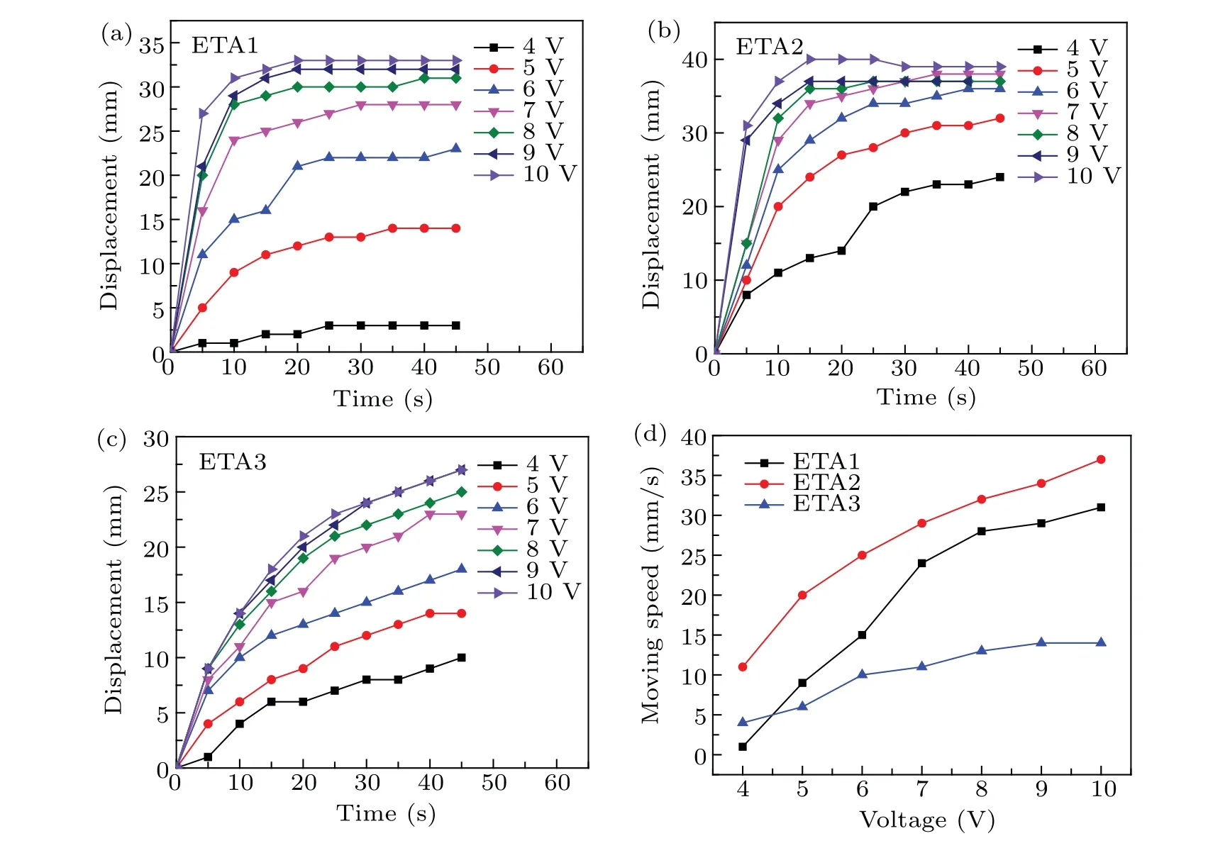
Fig.2. (a)–(c)Horizontal deformation of ETA1,ETA2 and ETA3. (d)Moving speed versus voltage for ETA1,ETA2 and ETA3.
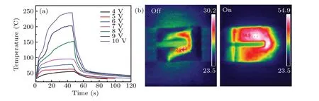
Fig.3. (a)Temperature vs. time curves of ETA2 under different voltages and(b)IR thermal images of the device at off and on states.

Fig. 4. (a)–(c) Curves of current and power with voltage of ETA1, ETA2 and ETA3. (d) Comparison of maximum deformation of the electrothermal actuators with different thickness under different voltages.
Figure 4(a)shows the current–voltage and power–voltage curves of the EAT1.As the voltage rises,the current and power increases linearly, resulting in the enhancement in the deformation amount and deformation rate. The current and thermal power of EAT2 and EAT3 has similar rising tendency to EAT1(Figs. 4(b) and 4(c)). Figure 4(d) depicts a comparison chart of the maximum deformation of the electro-thermal actuators with different thicknesses under different voltages. From the previous section,it can be seen that the DC voltage has a significant effect on the deformation of the electro-thermal actuator. Under the same voltage, the film thickness also has an obvious effect on the deformation. CNT/PDMS composite films with thickness of 0.3 mm,0.6 mm and 1 mm are used in EAT1, EAT2 and EAT3, respectively. When the same potential is applied,the variation of EAT2 is the largest. The initial deformation of EAT1 is less than that of EAT3 and when the voltage is higher than 5 V, its deformation is larger than that of EAT3. Because of its large thickness and high hardness,the deformation of EAT3 is limited under the same voltage. The maximum deformation of EAT1, EAT2 and EAT3 is 33 mm,40 mm and 27 mm, respectively. Although EAT1 has small thickness and low hardness,the amount of thermal expansion caused by PDMS is small,leading to short movement distance in horizontal direction. The thickness of the PDMS layer in EAT2 is moderate,which has proper hardness and can produce enough thermal expansion,so its deformation is the biggest.In addition,when the potential is lower than 7 V,the deformation of the three samples is significantly different, but this difference is gradually weakened above 7 V.
In order to better study the bending performance of the actuators, the bending curvature was introduced to quantify the drive performance. The principle of the calculation of the bending curvature is shown in Fig.5(a). In the initial state,the driving force is vertical,and the length of the SWCNT/PDMS actuator is represented byL. In the bent state, the following equations are available:
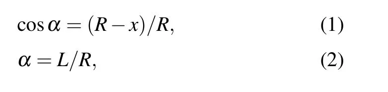
whereRis the radius of the arc of the bent actuator,andxis the horizontal free end displacement.α/2 is the chord tangency angle, and the arc bend angle isα. Therefore, the value of curvatureK=1/Rcan be derived by numerically solving the following equation:

A comparison of the maximum bending curvatures of the ETAs at different voltages and for different thicknesses is shown in Fig. 5(b). The maximum bending curvature of ETA2 can reach 0.46 cm−1at a low voltage of 7 V, which is larger than that of the reported MWCNT/rubber actuator(0.29 cm−1).[11]As the drive voltage increases, the bending curvatures of the ETAs also increase. However, compared to ETA1 with a thickness of 0.3 mm and ETA3 with a thickness of 1 mm,ETA2 with an appropriate thickness of 0.6 mm achieves the largest bending curvature.
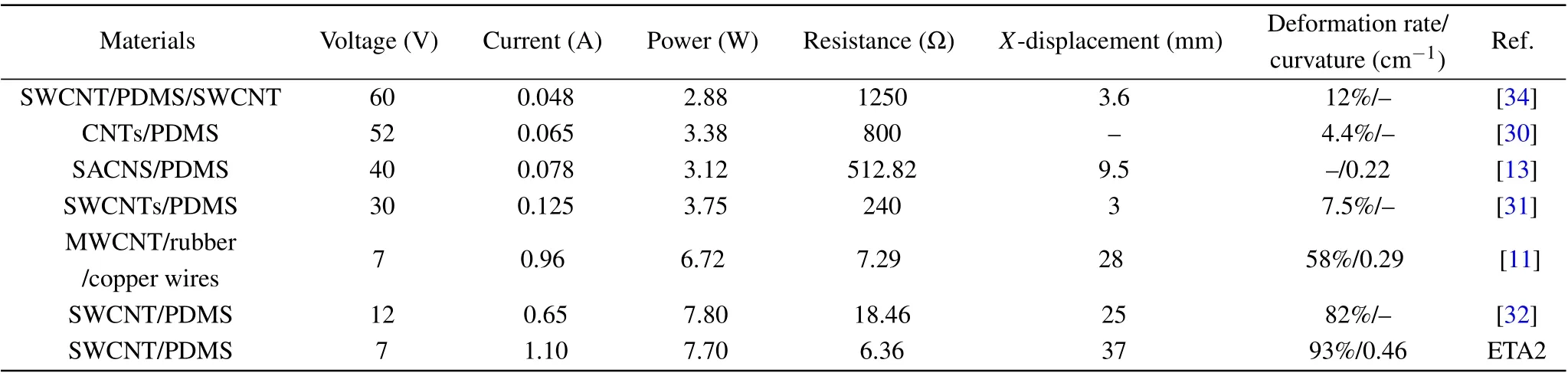
Table 1. Comparison between the maximum deformation of the ETAs based on CNT composites.
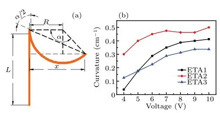
Fig.5.(a)Actuator with correlative parameters for calculating the bending curvature.(b)Comparison of maximum curvature of the electrothermal actuators with different thickness under different voltages.
The comparison of deformation performance of electrothermal drivers based on CNT/polymer composites is shown in Table 1. It is reported that a maximum displacement of 3.6 mm can be obtained under the stable condition of 60 V/48 mA,and the ratio of tip deformation to device length is 0.12.[34]Chen reported a carbon nanotube (5 wt%)/PDMS matrix achieved a strain of 4.4%at 52 V.[30]After three years,they also found that the actuator based on bilayer carbon nanotubes(SACNS)/PDMS could start to bend immediately when the DC voltage reached 40 V and the current was 78.5 mA.[13]After 5 s, the displacement reached 9.5 mm with a bending curvature of 0.22 cm−1. With a strain of up to 7.5%at 30 V,the ETA studied by Huet al.can lift a coin by almost 3 mm and produce a force output of about 6 g.[31]The actuator based on MWCNT/rubber/copper wires has a horizontal deformation of nearly 30 mm with a deformation rate of 0.58 under 7 V and 0.97 A.[11]Chenet al.reported that the SWCNT/PDMS ETA had a calculated horizontal displacement ratio of 0.82 at 12 V.[32]In this study,the maximum horizontal displacement of ETA2 reaches 37 mm(bending curvature is 0.46 cm−1)and the deformation rate is 0.93 at 7 V.It can be seen that the maximum deformation and deformation rate of EAT2 are obviously larger than the data of similar samples in the literature.
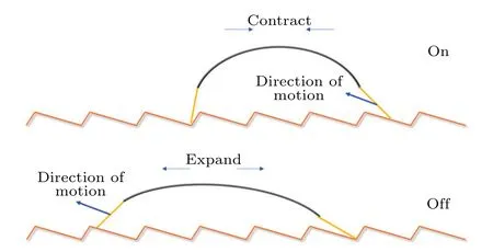
Fig.6. The motion analysis diagram of the ETSR at on and off states.

Fig.7. Motion screenshots of(a)ETSR1 at 12 V,(b)ETSR2 at 6 V and(c)ETSR3 at 7 V.
ETSRs with different electrode structures were assembled based on the CNT/PDMS films,and Fig.S2 shows their structure diagrams. Two zigzag copper guide rails were prepared to provide DC potentials and point of force for the ETSRs. As shown in Fig. 6, by controlling the on and off of the voltages, the robot makes corresponding contraction and stretching movements, thus producing “inchworm”-like movement. Figure 7(a) shows the motion screenshots of the four-legged ETSR1 at an interval of 10 s. Under 12 V/1.3 A, the ETSR1 crawls 9.5 mm in one minute with an average speed of 0.16 mm/s. However,the electrode feet of quadruped robot cannot remain contact with the copper rails at all times,because the CNT/PDMS composite film is easy to curl around.In addition,under 12 V,the temperature resistance limit of the composite film is reached, and the ETSR1 begins to smoke.To overcome the bad contact problem of the quadruped robot,a three-legged robot was prepared, which can ensure that the two electrode feet of the U-shaped film can always contact the rails. At 6 V/1 A,the three-legged ETSR2 with a thickness of 0.6 mm wriggles 6.5 mm after 100 s,and the average speed is 0.07 mm/s(Fig.7(b)). During the operation process,the three legs are always in contact with the guide rails, and no smoking phenomenon occurs. In addition, a composite membrane with a thickness of 1 mm was used to prepare a three-legged ETSR3. As shown in Fig. 7(c), when a voltage of 7 V is applied,the current reaches 1 A.The device moves 4.5 mm with a speed of 0.05 mm/s in 100 s. Because the composite membrane used in this device is thicker, more thermal energy is needed for bending,and the crawling speed is slower than that of ETSR1 and ETSR2.
4. Conclusions
In summary,electrothermal CNT/PDMS composite films were synthesized and used in ETAs. The deformation amount and deformation speed of the ETAs both dramatically increases with the growth of the applied DC potentials. The ETA2 with a 0.6-mm-thick CNT/PDMS film has the largest horizontal displacement of 40 mm. The ETA1 with a smaller thickness exhibits poor deformation performance because of low thermal expansion of the PDMS layer. For the ETA3,the thicker CNT/PDMS film has greater hardness, leading to low deformation. In addition, motion characteristics of the soft robots based on the CNT/PDMS films were also investigated. Compared with the four-legged ETSR1, the threelegged ETSR2 did not go off the copper rails. At a DC voltage of 6 V, the ETSR2 with a moderate thickness shows the best movement performance.
Acknowledgements
Project supported by the National Natural Science Foundation of China (Grant No. 51602021) and the Fundamental Research Funds for the Central Universities,China(Grant No.FRF-TP-18-023A2).
猜你喜欢
杂志排行

Chinese Physics B的其它文章
- Editorial:Celebrating the 30 Wonderful Year Journey of Chinese Physics B
- Attosecond spectroscopy for filming the ultrafast movies of atoms,molecules and solids
- Advances of phononics in 20122022
- A sport and a pastime: Model design and computation in quantum many-body systems
- Molecular beam epitaxy growth of quantum devices
- Single-molecular methodologies for the physical biology of protein machines