A review of arc-discharge method towards large-scale preparation of long linear carbon chains
2022-12-28YiFanZhang张一帆
Yi-Fan Zhang(张一帆)
Huzhou Key Laboratory of Environmental Functional Materials and Pollution Control,School of Engineering,Huzhou University,Huzhou 313000,China
Keywords: linear carbon chain,carbyne,carbon nanotube,arc-discharge method
1. Introduction
Carbon is one of the most abundant elements on earth and constructs the base of all creatures. The fundamental sp,sp2, and sp3hybridizations as shown in Fig. 1 enable carbon to own countless allotropes and compounds with different properties.[1]The low-dimensional allotropes of carbon take an important place in the development of nanoscience and nanotechnology. The discovery of fullerene (quasi-0D),carbon nanotubes (CNTs) (quasi-1D) and graphene (2D) renews human’s knowledge of nature and contributes to new applications.[2–5]The majority of researches on carbon allotropes focus on sp2,sp3and their hybrid systems,however,the research on sp-hybridized structures is relatively backward.The sp-hybridized structures own linear shape with a diameter of only one atom,namely,linear carbon chains(LCCs),which can be considered as a true one-dimensional(1D)nanomaterial.
LCCs are constructed either by alternative single-triple C–C bond or successive double C–C bond, named polyyne and cumulene,respectively. Theoretical studies indicated that polyynic LCCs should be semiconducting with a band gap close to 2 eV, while cumulenic LCCs are metallic with band gap of smaller than 150 meV, according to their differentπelectron constructions.[6,7]However, most first-principle calculations agree with that cumulenes are unstable and will transform to polyynes through Peierls distortion, generating bond alternative length (BLA).[8–11]Very recently, Romaninet al. reported the theoretical study considering quantumanharmonicity and revealed the transition between the two structures only occurs at extremely high and unphysical temperatures, explaining why experimental results only detect polyyne rather than cumulene.[12]Besides,finite LCCs and infinite LCCs are also distinguished,because the former is considered as a group of finite molecules usually containing other elements, whose properties are affected by length and end group,for instance polyynes terminated by hydrogen(C2nH2,n<10). While the latter can be treated as a one-dimensional crystal regardless of length and end-group effect. The term carbyne is used to name the allotrope purely constructed by parallel LCCs,which is also applicable to name individual infinite LCC now.[13–16]
LCC-based materials,especially carbyne are predicted to own promising properties,which have been well introduced by several reviews.[17–19]Briefly, as a true 1D nanomaterial, the specific surface area can reach 1.3×10⁴m2/g. Meanwhile,the strongest Young’s modulus,specific stiffness,and thermal conductivity in nature are expected. The special electronic and optical properties exhibit large potential towards nanodevice applications.[20–26]Whereas,to experimentally realize the practical applications of LCC-based materials is in its infancy.
The first attempt to synthesize finite LCCs can be traced back to Baeyer in 1885, however it failed.[27]Till 1950s,molecules containing cumulenic or polyynic fragment were found in several plants and fungi.[28–30]Bohlmannet al.succeeded in synthesizing polyyne molecule with length of ten carbon atoms terminated by functional group.[31,32]The term carbyne started to be used in the 1960s. At that period,different discoveries and experiments were reported to obtain carbyne-like allotropes, such as Chaoite found in Ries crater.[33,34]But no strict proof indicated the true existence of carbyne. The attempt on searching carbyne even contributed to the discovery of fullerene, however, the truth of carbyne remained controversial for a long time.[35–38]It is noted that LCCs have higher chemical reactivity with longer chain length, resulting in crosslink to form other structures,which hamper the high-concentration synthesis and long-term storage.[39–41]
To overcome the problem, the alternative strategy using hybrid structures to keep the stable existence of LCCs has been well developed in the last two decades. The typical examples with well-defined structures are illustrated in Fig. 2. Zhaoet al. found long LCCs with length of more than one hundred atoms can be encapsulated inside multiwalled carbon nanotubes in 2003.[42]The terms such as carbon nanowires(CNWs)and long linear carbon chain inside multiwalled carbon nanotubes (LLCC@MWCNTs) were used in relevant works. In this review, to distinguish from the finite LCCs (polyynes), the term LLCC@MWCNTs is chosen. Shiet al.found the carbon chain of more than 6000 carbon atomic lengths in double-walled carbon nanotubes(LLCC@DWCNTs), which keeps the world record to the date.[43]Sebastianet al. proved LLCC with a length of 230 atoms (the experimental limit in that work) has no evident length dependence,which means LLCCs agree with the definition of carbyne.[44,45]Tykwinskiet al.used functional group to protect polyyne molecules from cross-link reaction and largely lengthened polyynes to 48 carbon atoms. The property of those polyynes is no more determined by functional group,satisfying the definition of carbyne.[46,47]Recently,several wellknown progress such as LCCs between graphene layers or CNTs,[48–52]white carbon nanocrystal,[53,54]linear metalated carbyne,[55]and cyclocarbon[56]also largely extended the possible existence of LCCs. Besides those forms with 1D structure, graphyne is a group of two-dimensional(2D) allotropes composed of sp–sp2hybridization,owning abundant predicted structures.[57,58]As one of them,graphdiyne has been successfully synthesized.[59,60]With the rapid development of LCCbased materials,some potential applications were exploited in the field of gas sensor, photoluminescence, electrochemistry,and bioautography, providing a bright prospect towards new nanodevices.[61–65]
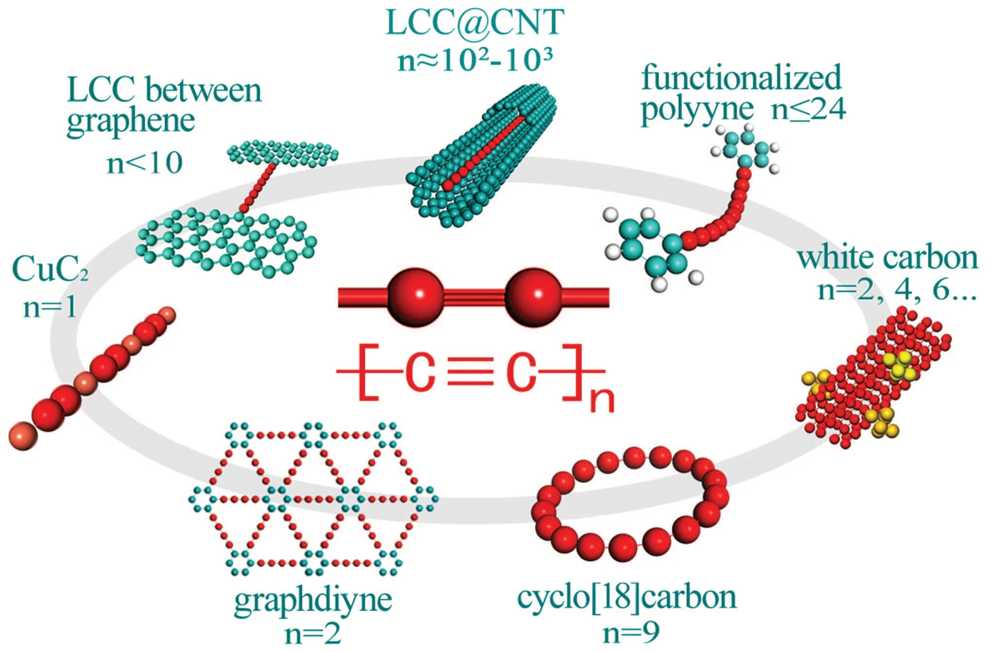
Fig.2.Illustration of recent progress of LCC-based materials with welldefined structures.
To develop simple and efficient methodology is a necessity to support further basic and applied researches. Table 1 lists the main methods to prepare materials containing carbon chains to the date. Generally,the methods can be categorized as chemical and physical means from 5 K to over 4000 K.The pure chemical methods such as surface chemical synthesis and liquid-phase organic synthesis based on coupling reaction start from alkynyl precursors,being able to precisely fabricate structures like functionalized polyynes,metalated carbyne and cyclocarbons. The annealing methods use single-, double-,and multi-walled carbon nanotubes as raw materials to grow LLCCs inside through recrystallization at high temperature.Meanwhile,the nanoreactor method fills carbonous molecules into the hollow space of CNTs to promote the growth of carbon chains in annealing method, which has little increased cost but significant improvement. The arc-discharge, laserablation and cluser-beam methods mainly driven by physical means provide local high temperature up to the melting point of graphite in gas or liquid phase environment. The different carbon sources are decomposed to be small clusters and even ions. Through rapid cooling, LCC-based materials form on substrates or into the environment. The difficulty and applicability of the above methods can be qualitatively compared by the cost of experiments and the yield of products. The liquid-phase synthesis, annealing, nanoreactor and arc-discharge methods are relatively low-cost and high-yield.Among them,the arc-discharge method is the only method being able to produce both finite and infinite LCCs (polyynes and LLCC@MWCNTs) on the basis of different conditions and parameters. This method has the advantages of very low cost and simple set. LCCs can be generated from graphite or organics only in tens of seconds. Thus,arc-discharge method can be applicable for large-scale researches of carbon chains at present.
In this article,the approaches using arc-discharge method to produce LLCC@MWCNTs are summarized. The present state of researches on the apparatus, experimental conditions and mechanism are discussed in detail. The widely used characterization techniques to evaluate the relevant products are also reviewed. The remaining challenges in this field are presented. This review aims to promote further research to overcome the proposed challenges and benefit the large-scale application of LCCs as well as arc-discharge method.

Table 1. The main methods to prepare LCC-based materials.
2. Preparation of LLCC@MWCNTs via arcdischarge method
The arc-discharge method is a well-developed and easy technique, which has been used to produce thin films and nanostructures in different conditions. The first carbon nanotube sample was also obtained by this method. To date,the arc-discharge method has been developed to realize the large-yield production of various kinds of carbon nanomaterials such as fullerene,multi-layers graphene,and CNTs.[78–80]The preparation of LLCC@MWCNTs basically relies on the preparation of MWCNTs with similar apparatus, conditions and mechanism.
2.1. The apparatus and conditions of arc-discharge method to prepare LLCC@MWCNTs
The common and core parts of apparatus of arc-discharge method are anode and cathode electrodes connected with current supply(usually a welding machine), and a proper chamber,as shown in Fig.3(a). In the case of the first synthesis of LLCC@MWCNTs, the electrodes were high-purity graphite rods connected with direct current (DC) arc generator. The chamber was connected with a vacuum pump and gas path system,providing a low-pressure hydrogen environment.The DC was applied between two vertically placed electrodes to generate an arc plasma in the gap for tens of seconds. After the arcdischarge process, the anode was ablated and a deposit with a black core surrounded by a grey shell was obtained on the surface of cathode,shown in Fig.3(b). LLCC@MWCNTs are in the black core,while the grey shell only contains graphite.Multilayer graphene sheets can be found outside of the grey shell.
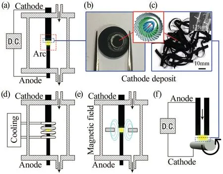
Fig. 3. Illustration of the apparatus and products of arc-discharge method. (a) The basic configuration of apparatus for hydrogen arcdischarge method. (b) The circular cathode deposit of panels (a), (d),and (e). (c) The tape-like cathode deposits of panel (f). (d) The configuration of gas cooling-enhanced arc-discharge apparatus. (e) The configuration of magnetic field-enhanced arc-discharge apparatus. (f)Rotating arc-discharge apparatus. Panel (c) is reprinted with permission from Ref.[89],©2012 by Elsevier.
The preparation of LLCC@MWCNTs was thought to be very strict since the first preparation. But further researches have largely extended the applicable conditions. Table 2 lists the different conditions and transformation of arc-discharge method to prepare LLCC@MWCNTs. The main adjustable factors are the material of electrode, the category and pressure of environment gas, and the current. Fundamentally,LLCC@MWCNTs only contain carbon and metallic catalysts are not necessary for the preparation of MWCNTs, differing from the preparation of SWCNTs and DWCNTs. Therefore,pure graphite can be recognized as the proper electrode material for the preparation of LLCC@MWCNTs. Additionally,Ni–Cr catalyst and boron were tried to promote the growth of LLCC@MWCNTs. The presence of the Ni–Cr catalyst has no obvious influence on the formation of LLCCs,while boron was reported to increase the productivity of MWCNT tape and the frequency to observe LLCCs. The category of gas was thought not critical for the growth of LLCC@MWCNTs. Different kinds of background gas have been applied into the arcdischarge process, for instance, hydrogen, deuterium, helium and argon. Scuderiet al. reported a special case preparing LLCC@MWCNTs immersed in liquid nitrogen,which can be considered as nitrogen. However, it is noted that the corresponding optimal current and pressure parameter under certain gas environment are different, and the parameter windows to prepare LLCC@MWCNTs are relatively narrow compared to that of usual MWCNTs. The growth of LLCC@MWCNTs is sensitive to the change of environment. Jinnoet al. reported to produce LLCC@MWCNTs in the mixture of H2–N2and LLCCs were found absent when nitrogen was over 20%. The range of applicable current to produce LLCC@MWCNTs in hydrogen is narrow(near 50 A–60 A).By applying additional gas cooling and static magnetic field around the arc plasma shown in Figs. 3(d) and 3(e), the applicable condition was largely extended to a higher and lower current limit, respectively. In addition, Kimet al. provided an apparatus design shown in Fig.3(f)using a movable and hollow graphite anode and a rotating highly resistive cathode to realize the continuous production of MWCNTs in the form of a tape(Fig.3(c))under atmospheric condition, which is also able to prepare LLCC@MWCNTs and shows the feasibility towards the industrial preparation.[89]Though the macro aggregations such as circular deposits or tapes of LLCC@MWCNTs obtained in different conditions may be different,the basic structure of soobtained LLCC@MWCNTs are essentially the same according to further characterizations.

Table 2. Reported arc-discharge conditions to prepare LLCC@MWCNTs.The units 1 Torr=1.33322×10² Pa,1 bar=105 Pa.
2.2. The mechanism of the growth of LLCC@MWCNTs in arc-discharge process
Differing from the growth of LLCC@SWCNTs and LLCC@DWCNTs driven by decomposition and recrystallization of carbon sources inside CNTs below∼1800 K,arc discharge generates a plasma with temperature higher than the melting point of graphite and leads to the ablation of anode.Figure 4 shows the schematic diagram of the arc-discharge process discussed in the previous work.The graphite on anode is decomposed to carbon species vapors including C+,C,C2,and other Cnclusters,which finally deposit on the cathode and form LLCC@MWCNTs.

Fig. 4. Illustration of arc discharge generated between anode and cathode.Figure reprinted with permission from Ref. [87], ©2018 by Royal Society of Chemistry.
The study on the growth mechanism of LLCC@MWCNTs can be summarized into two aspects. The one aspect concentrates on the growth condition. Zhaoet al.thought the growth mechanism of LLCCs is similar with the smallest CNTs,[90,91]since they were prepared in similar condition. Meanwhile the smallest CNTs and LLCCs are both meta-stable structures which require high energy to form and have to be protected by outer CNTs. Zhanget al.analyzed the mechanism in the gas cooling and magnetic field enhanced experiments appealing to the previous researches on the plasma physics of arc process to produce MWCNTs. It is concluded that the applicable parameters enable a high temperature of the plasma and maintain a relatively high ratio of the density of C+and C clusters,which benefit the high-quality growth of MWCNTs and satisfy the growth of LLCCs.
The other aspect is about the detailed process of the crystallization of LLCC@MWCNTs. Kanget al. suggested the close-end growth model of metal-catalyst free MWCNTs is applicable for the growth of LLCCs inside MWCNTs, rather than open-end growth model.[82,92,93]In that opinion, the remaining carbon atoms inside the proper innermost tube generated LLCCs through a super-cooling process from the outer surface towards the internal part.
The consensus among those researches can be concluded that a high-purity growth of MWCNTs benefits the growth of LLCCs owing to the protective effect of nanotube,meanwhile,the growth of innermost tubes with diameter of∼0.7 nm is essential for the stable existence of LLCCs because of van der Waals interaction between LLCC and innermost nanotube.[94]
2.3. The characterization technique to evaluate products
The common ways to characterize all kinds of LLCC@CNTs are Raman spectroscopy and transmission electron microscopy (TEM) in the present researches. Raman spectroscopy is recognized as the best tool to fast identify the structural features of carbon materials with different hybridizations. The LLCC@MWCNT products, no matter the circular deposits or tapes, can be directly measured by Raman spectroscopy without postprocessing. The typical multiple LLCC peaks can be observed from 1780 cm−1–1880 cm−1in most works,as shown in Fig.5(a),which is obviously distinguished from the D-band and G-band of MWCNTs, and is lower than the Raman frequency of finite polyynes.[95]The parallel relation of carbon chain and MWCNTs has been proved by polarized Raman measurement, where the Raman signal of LLCCs along the axial direction of MWCNT bundle was much stronger than that along the radial direction.[42]It is well-recognized that the Raman signal originates from the stretching mode(corresponding to the LO phonon)of sphybridized carbon chain,where the frequency is positively related to BLA of polyynic bond structure.[43,85]As important evidence of carbyne,the property of LLCCs has been proved not length-dependent via the tip-enhanced Raman scattering study on LLCC@DWCNTs, where the peaks with lower Raman frequency come from LLCCs surrounded by innermost CNTs with lower diameters,which is different from the strong length-dependent effect of polyynes. Meanwhile, the resonance Raman studies shown in Fig.5(b)indicate LLCCs own the optical band gap of 1.8 eV–2.3 eV and LLCC peaks at lower frequency correspond to lower optical band gap.[96]The linear relations among Raman frequency, optical band gap,and diameter of protective CNTs have been concluded in those works, as shown in Figs. 5(c)–5(f). Thus, the distribution and relative intensity of LLCC peaks can be a convenient indicator to qualitatively evaluate the filling ratio of certain LLCC@CNTs. But note that the comparison of filling ratio must be done under same measurement parameters on homogeneous samples. The Raman laser spot should be the larger the better to get an average result.

Fig.5. Raman spectrum of LLCC@MWCNTs,resonance Raman profile of LLCC@DWCNTs and correlation among diameter of innermost CNTs,Raman frequency,and band gap of LLCCs. (a)Typical Raman spectrum of LLCC@MWCNTs obtained by hydrogen arc discharge. (b)Resonance Raman excitation profiles for six LLCC peaks. (c)Raman frequency of LLCC as a function of the encasing inner tube’s diameter.(d)Raman frequencies of LLCCs for which no RBM from the inner tube could be detected. (e)Band gap EG as a function of Raman frequency.(f)LLCC band gap EG as a function of inner CNT diameter d. Panel(a)is reprinted with permission from Ref.[87],©2018 by Royal Society of Chemistry. Panel (b) is reprinted with permission from Ref. [96], ©2017 by American Physical Society. Panels (c)–(f) are adapted with permission from Ref.[44],©2018 by American Chemical Society.
Besides the correlation with electronic properties,the Raman peaks of LLCCs can be used to investigate the mechanical and thermodynamical properties. The pressure-induced red shift of Raman frequency and irreversible changes under over high pressure has been studied in several works.[97–99]The pressure-dependent responses for Yonng’s modulus,Gr¨uneisen parameter, and strain were also reported.[100]The temperature-dependent behavior of LLCC peaks reveals the thermal properties and allow LLCC to be a temperature prob.[42,101–103]
The micrograph observation via HRTEM firstly revealed the existence of LLCCs with length longer than 20 nm encapsulated inside the innermost tube of MWCNT in Ref. [42].In 2015, Andradeet al. unambiguously demonstrated the existence of a 1D structure present within the innermost CNT through HRTEM images under defocus condition and the cross section of an individual LLCC@MWCNT,where LLCC in the center of innermost CNT was observed, as shown in Fig.6.[85]It is noted that the statistics by HRTEM,though expensive and low-efficiency,is still the only approach to quantify the filling ratio of LLCCs. Scuderiet al.presented a statistical result by TEM that all LLCCs were found inside the innermost tubes narrower than 1 nm.[86]Actually, the diameters of innermost tubes were always reported to be close to 0.7 nm,which was the result of van der Waals interaction between LLCCs and protective nanotubes,as mentioned above.

Fig. 6. HRTEM micrograph of LLCC@MWCNTs. (a), (c), (d) and (e) HRTEM images of LLCC@MWCNTs. (b) An integrated intensity profile of the dashed box area in panel (a). (f) High-angle annular dark field (HAADF) image using the scanning transmission electron microscopy(STEM)mode to observe a cross section of an MWCNT containing a carbon chain in the center of the innermost CNT.(g)Selected area electron diffraction of an MWCNT cross section. The dashed square in panel(f)is zoomed in panel(h). (i)The treated image of panel(h).Reprinted with permission from Ref.[85],©2015 by Elsevier.
2.4. The remaining challenges of arc-discharge method to produce LLCC@MWCNTs
It is noted that the arc-discharge method is the only way to produce LLCC@MWCNTs directly from graphite. The largescale preparation technique has been developed, especially through the design of rotating apparatus under atmospheric environment. But the feasibility to produce LLCC@DWCNTs or LLCC@SWCNTs by arc discharge is not implemented yet. Though the mechanism was discussed, the growth of LLCC@MWCNTs is difficult to be theoretically simulated as the annealing formation of LLCC@DWCNT orin-situobserved as surface chemistry of polyynes. Besides, the technique towards fast quantitative determination of the filling ratio of LLCCs remains urgent and challengeable,while normal Raman spectroscopy only presents qualitative result and TEM statistics is low-efficiency.
3. Conclusion and perspectives
The recent progress to prepare LCCs is briefly introduced in this review. The arc-discharge method is one of the most practical ways to prepare LLCC@MWCNTs because of its low cost and simple set. Different gas background,current, and pressure conditions have been applied to prepare LLCC@MWCNTs. The additional modifications of arcdischarge apparatus help to extend the optimal conditions and realize large-scale preparation. The studies on mechanism indicate the growth of LLCCs relies on the high-quality growth of MWCNTs. Raman spectroscopy and TEM as the common characterization technique to efficiently evaluate the products are recommended. Lastly,the remaining challenges in further study are proposed.
The preparation of different LCC-based materials has been realized for experimental study,and the industrial preparation of LLCC@MWCNTs can be expected. Almost all relevant studies cited the bright prospect of LCCs presented by theoretical studies. However, only a few of them have been exploited to applications, which have no relationship with the mentioned outstanding properties. The potential usage of LLCC@CNTs is still highly desired to be developed. The fast selective growth and separation of LLCC@CNTs with different band gaps will be challengeable but desirable approaches towards new nanotechnology.
Acknowledgement
Project supported by the Fund from the Huzhou Key Laboratory of Environmental Functional Materials and Pollution Control at Huzhou University.
杂志排行

Chinese Physics B的其它文章
- Editorial:Celebrating the 30 Wonderful Year Journey of Chinese Physics B
- Attosecond spectroscopy for filming the ultrafast movies of atoms,molecules and solids
- Advances of phononics in 20122022
- A sport and a pastime: Model design and computation in quantum many-body systems
- Molecular beam epitaxy growth of quantum devices
- Single-molecular methodologies for the physical biology of protein machines