Development of a cryogen-free dilution refrigerator
2022-12-28ZhongqingJi姬忠庆JieFan樊洁JingDong董靖YongboBian边勇波andZhiGangCheng程智刚
Zhongqing Ji(姬忠庆) Jie Fan(樊洁) Jing Dong(董靖) Yongbo Bian(边勇波) and Zhi-Gang Cheng(程智刚)
1Beijing National Laboratory for Condensed Matter Physics and Institute of Physics,Chinese Academy of Sciences,Beijing 100190,China
2School of Physical Sciences,University of Chinese Academy of Sciences,Beijing 100190,China
3Songshan Lake Materials Laboratory,Dongguan 523808,China
Keywords: cryogen-free dilution refrigerator,heat exchanger,cooling power,helium
1. Introduction
An environment at ultra-low temperature is important and essential to a wide range of studies in physical science such as fractional quantum Hall effects (FQHE)[1–5]and topological quantum materials,[6–8]as well as developments of information techniques such as quantum computations.[9–12]“Order”is a key concept in physical science as it describes coherent motions of matter. However, coherent behaviors are always difficult to observe at high temperatures due to thermal fluctuations. As a result, ultra-low temperatures are needed to suppress thermal fluctuations.Besides,ultra-low temperatures are important for developments of novel technologies. Qubits,basic element for quantum computations (QC), are realized based on two-level systems (TLSs) of “0” and “1” states.A prerequisite to realize a qubit is that thermal fluctuation(namely broadening of energy levels) must be much smaller than the energy gap of TLSs so that quantum states can be reliably distinguished and maintained. Superconducting quantum computations, as a major route for QC,are realized based on superconducting quantum interference devices(SQUID).[13]It makes use of energy sub-levels(∆g/kB∼0.1 K)within the superconducting gap (∆s/kB∼1 K), and ultra-low temperature as low as 10 mK is obviously essential.
Dilution refrigerator(DR)is by far the best and most convenient method to generate continuous ultra-low temperature environment around 10 mK.Its cooling power originates from the transfer of3He atoms from its rich phase to dilute phase in4He. Due to the substantially high price,3He flow must be closely cycled,so that precooling the recycled3He is critically important.Conventional DR utilizes a4He evaporating pot operating at 1.5–1.8 K as a precool stage. Operation of the pot is sustained by regular refill of liquid4He, so that an accidental shortage of liquid helium would introduce interruptions,not to mention time and helium wasted during processes of warming and cooling. Besides,dilution unit of a conventional DR is restricted within a small radial region to limit the evaporation of liquid helium.
With the invention of Gifford–McMahon (GM)[14]and pulse tube cryocoolers,[15]a low temperature of 3 K can be created solely using electricity. The4He evaporating pot can be substituted by the cryocoolers, making it a“cryogen-free”dilution refrigerator (CFDR). Besides saving helium evaporation, a major beneficial byproduct of CFDR is that spatial restriction is lifted, bringing extensive potential in applications. A famous practice performed on CFDR is superconducting quantum computations,which usually require tens or hundreds of coaxial cables that otherwise would be impossible to fit in a conventional DR.
In this paper we describe our design, construction, and test cooling of a homemade CFDR. A base temperature of 10.9 mK was reached for continuous circulation,and 8.6 mK for single-shot operation.We first describe its operating mechanism,and then illustrate designs of main components. A test cooling from room to base temperature is demonstrated, and discussions for possible improvements is given at last.
2. Operating mechanism of dilution refrigerator
Liquid4He experiences a superfluid transition at 2.17 K below which its viscosity vanishes. Only a few excitations exist in superfluid4He, including longitudinal phonons and rotons. On the other hand, the liquid state of3He behaves as Fermi liquid before reaching superfluid transition at around 2 mK.[16,17]When mixed in liquid4He, quantum statistics of3He disrupt phase coherence of superfluid4He, effectively suppressing its superfluid transition to lower temperature(see Fig.S1 in supplementary materials[18]). With increasing3He concentration (x3), superfluidity onset temperature decreases from 2.17 K(withx3=0)to 0.867 K(withx3=67.5%),below which the mixture starts to phase separate into3He dilute phase and rich phase. Unlike conventional binary phase separation, a finite concentration of 6.6%3He is resolved in the dilute phase even at absolute zero (see supplementary materials for details[18]). This anomaly is associated with binding energy of helium atoms in the liquid state of each isotopes,which is caused by quantum nature of helium.The binding energy of4He atom isE4/kB=6.61 K[19]in liquid3He,smaller than the energy ofL4/kB=7.20 K in liquid4He,[20]leading to separation of pure3He phase in the limit of absolute zero.In marked contrast,the binding energy of a3He atom in liquid4He isE3/kB=2.785 K,[21]larger than its binding energy ofL3/kB=2.473 K in liquid3He.[22]Such an inversion of energy scales leads to solubility of3He in the dilute phase forming a Fermi liquid system of quasi-particles. The energy discrepancy betweenE3andL3is compensated by Fermi energy of the3He quasi-particles in the dilute phase, which is given byEF∝x2/33 .EFincreases untilx3reaches 6.6% when balance of chemical potential is reached across the phase boundary.The solubility also mildly increases with temperature,approximately following the dependence ofx3=0.066(1+8.3T2)forT<0.1 K due to the mild temperature dependence of the binding energies.[23]
The abnormal finite solutibity of3He in the dilute phase provides the fundamental mechanism for DR operation:When phase separation takes place,the rich phase floats above the dilute phase due to its smaller density and has smaller enthalpy.Thus transfer of3He from the rich phase to the dilute phase absorbs heat,generating a cooling power
whereH3is the enthalpy (subscript “d” for dilute phase and subscript“r”for rich phase),and ˙n3is the molar transfer rate of3He atoms across the phase boundary. For simplicity, we takex3d=6.6% andx3r=100%. The balance of chemical potential between the dilute and rich phases gives
whereSd(r)is the entropy of the dilute(rich)phase. Thus the enthalpy of the dilute phase is given by

It can be seen that the cooling power isT2-dependent,and proportional to the rate of3He circulation. The circulating rate is constant along the entire path,while two interfaces play important role. For one hand, the interface between the rich and dilute phases within the mixing chamber needs to be well maintained;for the other hand,the liquid–vapor interface within the still chamber also needs to be maintained at appropriate temperature in order to promote3He’s evaporation while to suppress4He from evaporation in the meantime.
3. Details of key components
Transfer of3He from rich to dilution phase can be realized by pumping3He out of the dilute phase and maintaining a chemical potential gradient across the phase boundary. Considering that3He must be closed-cycled because of its scarcity and high expense, a schematic diagram of major components of DR is shown in Fig.1 to demonstrate the flow path of mixtures (mostly composed of3He). Take the pump as a mark,the cycle can be divided into pump path(colored in blue)and return path(colored in red). The returning gas flow is at room temperature before entering the return line. Therefore, precooling of the returning mixture is necessary and important.To minimize the heat load along the return path,heat exchangers between the outgoing and incoming mixtures must be carefully designed for a satisfying precooling efficiency, and this is one of the most important factors for designing key components of the dilution unit. In this section,we will describe details of each major component along the flow direction,starting from the mixing chamber.
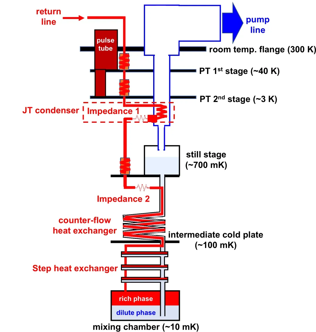
Fig.1. Schematic drawing of major components and structure of cryogenfree dilution refrigerator. The return path is colored in red and the pump path is colored in light blue and white.
3.1. Mixing chamber
Mixing chamber is the place where liquid mixture phaseseparates and transfer of3He across the phase boundary takes place. It is the end of the return line and the start of the pumping line. To maintain a chemical potential gradient,the pumping tube is inserted near the chamber bottom to pump3He out of the dilute phase, while the return flow is injected from the chamber top into the rich phase (see Fig. 2(a)). With cooling power originating from the boundary of the two phases,reaching thermal equilibrium between the chamber wall and the liquid mixture is important and non-trivial. Kapitza resistance between liquid helium and metal (copper for our case) is significant at ultralow temperatures:ARKT3=200–300 cm2·K4·W−1between liquid helium and copper below 100 mK, whereAis the contact area,RKthe thermal resistance,andTthe temperature.[26,27]A large Kapitza resistance would limit the thermal equilibrium between the liquid mixture and metal surface. With heat, vibration, and black-body radiation directly loaded to the mixing chamber,there could be significant temperature elevation of the mixing chamber plate compared with the liquid. For a regular cylindrical geometry with diameterφ=5 cm and heighth=5 cm,RK=1.7–2.5 mK/µW. A minute heat load of 10 µW will cause a nonnegligible temperature rise of about 20 mK. To suppress the rise,we fabricated a silver powder heat exchanger to the bottom plate with a diameter ofφ=5 cm, height ofh=3 mm,and a total surface area ofA ≈300 m2. The exchanger reducesRK≈70–100 nK/µW, significantly suppressing the temperature elevation under 1µK(with a heat load of 10µW).Details of packed silver-powder heat exchanger will be discussed in Subsection 3.5.

Fig.2. Schematic drawing of(a)mixing chamber and(b)still chamber.

3.2. Still chamber
Design of still chamber is shown in Fig. 2(b). The main function of still chamber is to evaporate3He from liquid4He.It is half-filled by liquid helium,and maintained between 0.6 K and 0.8 K to maximize the pumping rate of3He because vapor pressure of3He is about two orders of magnitude higher than that of4He in this temperature range. Consequently, the3He concentration in liquid phase is less than 1%,generating a concentration gradient which constantly drives3He from mixing chamber to still. Strictly speaking, still can be cooled down below 0.5 K given a powerful pump is used. However,such a low temperature is not efficient for3He evaporation, thus affecting the base temperature and cooling power of the mixing chamber. Therefore, a heater and a thermometer are attached to the still stage to control its temperature within the optimized range.
Helium vapor right above the still chamber is still at low temperature and can be utilized to precool the returning gas.This is realized by inserting a section of the return line in the still pumping line, requiring a large diameter of 40 mm for the pumping line. In this case,black-body radiation along the pumping line could be a main source of heat leak to affect the operation of still. Several methods to minimize the radiation include installation of blocking fins inside the pumping line and making the line in zig-zag shape. We took the latter option and heat-sank the pumping tube to the two stages of pulse tube PT1 and PT2.
3.3. Joule–Thomson(JT)condenser
After being pumped out, the mixture (mostly3He) will have to be recycled and returned to the dilution unit.Thorough precooling and condensation need to be accomplished before it reaches the stage of still chamber,otherwise tremendous heat leak will elevate its temperature and prevent normal operation.In our system,the returning gas is firstly precooled to 3 K by heat-sinking to PT1 and PT2 stages.It is less effective in comparison with conventional“wet”DR where incoming mixture gas is precooled by helium bath (at 4.2 K) and 1 K pot (below 2 K), with which condensation could almost be finished.Therefore,CFDR instead has to utilize Joule–Thomson effect,namely, cooling effect of adiabatic expansion, to accomplish condensation.

Fig.3. Isotherms of 3He enthalpy as functions of pressure. Numbers indicate temperature for each curve in Kelvin. The shaded area labels coexistence of liquid and vapor. The red dashed lines depict the process of 3He condensation by JT condenser. The figure is regenerated from Refs.[31,32].
Enthalpy isotherms are plotted in Fig. 3, showing that gas and liquid phases coexist below the critical point (Tc=3.309 K,Pc=1.146 bar). A typical trajactory of precooling and condensation is depicted by the dashed arrows. With a returning pressure around 0.8 bar and final temperature of 3 K,the precooling process at stages of PT1 and PT2 is shown from“A” to “B”. The position of status “B” could be within the phase-coexisting (shaded) region, or just below it, depending on how well the mixture is precooled. Adiabatic expansion process from“B”to“C”boosts the cooling below 2.0 K,and then further heatsink at the stage of still(T ≈0.7 K)completes the condensation. The process from“A”to“D”demonstrates the condensation process for normal operation when most of mixture gas is already condensed and the refrigerator is running near its base temperature. However,for initial cool-down at which still stage is at higher temperature (usually starting from 10 K),the cooling effect of adiabatic expansion is helpful to lower the still temperature at the beginning. Condensation can be accomplished as still is sufficiently cold.
The JT condenser is composed of heat-exchanger and expansion unit. Heat exchange between the returning gas and out-going gas is realized by winding brass tubes in spiral geometry and inserting it into the still pumping line(see Fig.S2 in supplementary materials[18]). The brass tube has outer diameter (O.D.) of 0.8 mm, inner diameter (I.D.) of 0.5 mm,and a total length of 6 m. Extra ports for inserting the return line are made by drilling holes on the side of flanges and hard welding stainless steel tubes with CF flanges.
An impedance (“Impedance 1” in Fig. 1) is placed after the JT exchanger for adiabatic expansion. The impedance is made by inserting a stainless-steel wire (with a diameter of 0.16 mm)into a CuNi capillary(I.D.=0.5 mm and length=2 cm). The impedanceZis measured as 1.2×1011cm−3,which is on the same order of magnitude with the values reported by other literatures.[25,31]Impedances which are 1–2 orders higher or lower have also been tested but the refrigerator could not work at its optimized state. Too large impedance seriously impedes the circulation,whereas too small impedance leads to too much heat leak to the mixing chamber. Condensation is completed at the heatsink attached to the still stage at about 0.7 K.Another impedance(“Impedance 2”)is placed after the heatsink. It has dual functions—to restrict the flow rate of liquid mixture so as to control heat loads to the following stages on one hand, and to prevent backflow of liquid mixture from the heat exchangers on the other hand.[33]The impedance value is set similar to that for“Impedance 1”.
3.4. Continuous heat exchanger
Having being completely condensed at the still stage,the liquid mixture needs to be precooled further before entering the mixing chamber. Heat flow through metallic tubes is heavily impeded by Kapitza resistance at such low temperatures.RKwas experimentally determined for interfaces between copper and liquid helium.[25]ARKT3≈10−3m2·K4·W−1forT=1 K and rises to 3×10⁻²m2·K4·W−1forT=0.1 K,whereAis the area of interface. To reduce the Kapitza resistance,the contact area should be as large as possible.
To precool the returning liquid helium efficiently, a continuous heat exchanger (CHE) is needed. It is composed of inner capillary and outer tube, both made of stainless steel.The inner capillary(O.D.=1.0 mm,I.D.=0.5 mm,length=20 m)is winded and inserted into the outer tube(O.D.=5 mm,I.D.=4 mm,length=4 m),which is then winded into a spiral solenoid with 10 turns and a diameter of 12 cm. The returning liquid flows within the inner capillary, exchanging heat with the outgoing liquid counter-flowing within the outer tube.
One must ensure that tubes do not crack during winding.This is especially critical for the inner tube since its wall is thin. It is advisable to fill the tube with water and freeze in liquid nitrogen. Ice can provide homogeneous stress and then prevent the capillary from collapse. On the other hand, the outer tube can be winded around a cylinder of desired diameter. This can be performed on a lathe to help achieving homogeneous stress and curvature. Two “T-shape” connectors are welded at both ends of the tube to let the inner capillary extend out for convenience of connection.
3.5. Step heat exchanger
We were able to cool down the mixing chamber down to 48 mK merely with CHE,but failed to conduct further cooling due to insufficient precooling. Therefore,heat exchanger with significantly larger interface area is necessary. To increase the interface area further,a step heat exchanger(SHE)is installed between CHE and mixing chamber. Heat exchange in SHE is still realized by counter-flow between the returning and outgoing mixtures. Two flows are separated by a metal plate with dimensions of 90×21 mm2. Silver powders are sintered to both sides of the plate to increase the effective interface area(Fig.4(d)). As shown in Figs.4(a)and 4(b),three SHEs connected in series are effective for further precooling the returning mixture,leading to a base temperature near 10 mK for the mixing chamber.
Fabrication of SHE is as follows. Silver sinter is made by compressing silver powders(average diameter of 2µm)in a rectangular mold(80×20 mm2). The applied compressing force is 80 kN, equivalent with a pressure of 500 bar. The thickness of the compressed sinters is about 1–2 mm. Two sinters are then fixed to the center of the rectangular stainlesssteel plate by moderate pressure and heat-treated at 200◦C for 1.5 hours in protective atmosphere. The heat treatment is effective to secure the attachment of sinters to the plate. On the other hand, tubes are welded to outer shells in advance, and the sintered plate is sandwiched between two outer shells and sealed at the edge. Three sealed SHEs are finally connected in series. Tubes,capillaries,and flanges are made of stainlesssteel, and all joints and sealings are tungsten-inert-gas (TIG)welded.
We have characterized silver sinters by measuring the average size of voids using transmission electron microscope(TEM). TEM (see Fig. S3 in supplementary materials[18])shows that the silver powders fuse to form a random interconnected matrix with average void size of∼1 µm. Its specific surface area is measured to be 2.52 m2/g by Brunauer–Emmett–Teller (BET) adsorption isotherm.[34]We have tried several fabricating protocols including using various powder sizes, compressing pressures, adjusting holding periods and ambient conditions for heat treatments. Specific surface area can be grossly controlled between 1 m2/g and 10 m2/g.Counter-intuitively,sinters with the largest specific area do not perform the best. This is because thermal conductance of liquid3He immersed in silver sinter is dependent not only on the surface area, but also on the void size. Small voids introduce too many interfaces, significantly increasing phonon scattering. The sintered layer cannot be too thick for similar reason.1–3 mm is an appropriate balance between sufficient surface area and moderate phonon scattering.The same procedure was used to fabricate the silver sinter within the mixing chamber.

Fig.4. (a)Drawing of step heat exchanger(SHE).(b)Top view of the SHE with blue arrows highlighting the flow path of outgoing mixture. (c) Bottom view of the SHE with red arrows highlighting the flow path of returning mixture. (d)Cross section of a single SHE to exhibit the internal structure.Silver powders(highlighted in green)are sintered and pressed to both sides of the middle plate which separates the return and pump paths.
4. Auxiliary components and designs
4.1. Thermal isolation
Connections between stages should be thermally weak to maintain temperature gradient when refrigerator operates. We use hollow stainless-steel tubes to ensure low thermal conductance and solid rigidity. Brass connectors are soldered to both ends of the tubes and bolted to stages by screws.
Multiple housekeeping thermometers and heaters are attached to each stage. To minimize heat leak brought by the housekeeping wires, AWG36 constantan wires are used.Heatsinks are set for all wires at each stage. The wires are varnished and wound around copper bobbins, and all heatsinks are bolted tightly to stages.
4.2. Heat switch
Pulse tube provides the sole cooling power for initial cooling before the mixing chamber reaches∼10 K. Strong thermal links are preferred for the stages below to follow the cooling of PT2. However,this is in contradictory with the requirement of weak thermal links. Therefore, a heat switch is necessary to satisfy both requirements.
To realize switching between weak and strong thermal links, independent high pressure flow path has been used for some commercial systems. The pressure could be as high as 3.0 bar,thus requiring compressor and high-pressure tubes. It also leads to risk of leaks as well as extra space inside the refrigerator. Alternatively, we proposed a mechanical heat switch (see Fig. 5 “A” and “B”). Two stainless-steel rods are aligned vertically with the first stick extending from room temperature flange to PT2 stage,and the second from PT2 stage to the still stage. Position of the first stick can be adjusted vertically by a twist-switch,and the second stick rests on a spring.Gaps between the sticks and the still stage are closed by pushing the first stick. Two copper braids heat-sink the sticks to PT1 and PT2 stages respectively, thus serving as strong thermal links between still and these two stages.
The stick only extends to the still stage because blackbody radiation may lead to significant influence to temperature profile of CHE,SHE,and mixing chamber. Instead,thermal links below the still stage are built with sintered alumina shunts (see Fig. 5 “F”). Thermal conductivity of alumina is∼1 W/cm·K above 50 K—sufficiently strong for initial cooling—but decreases to∼1 mW/cm·K at 2 K[35]—sufficiently weak to maintain temperature gradients. Alumina shunts have been proved effective for cooling above 50 K in cryogen-free4He and3He refrigerators.[36]The diameter of the shunts is 5 mm and the length is 3 cm. Copper caps are attached to both ends of the rods by epoxy (Stycast 2850), serving as anchor connectors to stages.
4.3. Vibration damping
Pulse-tube serves as the main cooling source for precooing returning gas mixture from room temperature down to 3 K.It is also the main source of mechanical vibrations which could prevent the fridge from reaching lower base temperature if vibration is not carefully damped. To damp vibrations,we connected the main flange of pulse-tube to the room-temperature stage via a sealed bellow(see Fig.5“C”).The bellow is flexible in its length, therefore being able to prevent vibrations from passing through it. Extra eight springs are mounted in parallel with the bellow to support the weight of the pulse tube.It is calculated that the resonance of the setup is at∼10 Hz,far away from the operating frequency of 2 Hz for the pulse tube.

Fig. 5. Schematic drawing and pictures of thermal links on the dilution refrigerator. (a) Controllable thermal link between PT1 and PT2 stages;(b)controllable thermal link between PT2 and still stages;(c)pulse tube connecting with room-temperature flange by a sealed bellow. The pulse tube is supported by eight springs for the purpose of vibration damping;(d)copper braids as strong thermal link between PT1 head and stage;(e)copper braids as strong thermal link between PT2 head and stage; (f) alumina rods as thermal links between the stages of still, intermediate cold plate, and mixing chambers.
Vibrations can also be transferred to the PT1 and PT2 heads due to its rigidity. To isolate the vibrations,strong copper braids are used to thermal-link the stages to the pulse tube heads instead of direct and rigid connection with both PT1 and PT2(see Fig.5“D”&“E”).The flexibility of the braids is efficient in isolating vibrations from the pulse tube to the stages.
4.4. Thermometers
Thermometers are mounted to each stage to monitor their temperatures during operations. Those on the stages of PT1 and PT2 are calibrated diodes (DT-670, Lakeshore Cryogenics),while those on the still stage,intermediate cold plate,and mixing chamber plate are RuOxthermometers(RX-102B-RS,Lakeshore Cryogenics)calibrated from 40 K to 8 mK.An extra RuOxthermometer is attached to the last SHE to monitor the temperature of mixture before entering the mixing chamber.
5. Test cooling
Temperatures and pressures during test cooling are shown in Fig. 6 and Fig. S5 in supplementary materials.[18]It took about 110 hours to cool from room temperature to base temperature. Heat switch was pushed down firmly at the start.The diode on PT1 stage did not work because of broken leads,but its failure is not crucial since PT1 always quickly cools down and stabilizes around 50 K due to its large cooling power. PT2 stage cooled down very fast,reaching about 30 K attA≈10 hour while the still stage was still around 150 K.The significant lag of still was due to the weakening of heat switch contact because of thermal contraction. Tightening the heat switch accelerated the cooling of the still stage.After running for 24 hours,stages of intermediate cold plate and mixing chamber reached below 40 K and their temperatures could be monitored.
The mixing chamber temperature reached below 9 K attB≈78 hour while the still was below 5 K. The heat switch was then disconnected and mixture was gradually pumped into the dilution unit. The returning pressure was gradually adjusted to about 900 mbar. Entry of mixture gas caused sudden temperature increases at the intermediate cold plate,SHE,and mixing chamber,accompanied by pressure increase in the pumping line. Nonetheless, still slightly cooled because the mixture served as extra thermal link to PT2 stage.AttC≈90 hour, all temperature from still to mixing chamber abruptly decreased and saturated near 1 K. These drops suggest accumulation of liquid in the dilution unit. However,still temperature being higher than stages below hints that the still chamber was empty and liquid resided only in the mixing chamber.
The still temperature abruptly dropped attD≈94 hour,accompanied by sudden decrease of pumping pressure,marking the existence of liquid in the still chamber. At the same time, the mixing chamber started to cool further below 0.9 K— entering phase separation regime. It suggests that there was enough liquid mixture to support dilution process. As shown in Fig.6(b),the mixing chamber cooled below 20 mK at around 97 hours,and slowly approached to its base temperature at around 10.9 mK while running with continuous circulation.Meanwhile,intermediate cold plate was around 45 mK,still around 780 mK,and returning pressure was stable around 300 mbar. We noticed that the last SHE was at slightly higher temperature than the intermediate cold plate. There are two possible reasons: (1) the thermometer was in non-ideal thermal equilibrium with the SHE because of the surface curvature and weak bonding;(2)precooling of the returning mixture was non-ideal and needed to be improved.
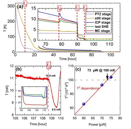
Fig.6. (a)Time dependence of temperatures at every stage except PT1. The inset is the zoom-in view when mixing chamber reached below 10 K.Several timestamps are marked,including: tA –re-tightening heat switch;tB –disconnecting heat switch and sending mixture into the dilution unit; tC –liquid starting to accumulate within the mixing chamber;tD –dilution process started. (b)Temperature of mixing chamber near its base temperature for continuous circulation and single-shot operation. Inset: Temperature variations for the mixing chamber,intermediate cold plate,and the last SHE when running at base temperatures and single-shot operation. tE marks the start of temperature drop associated with single-shot operation. (c) Measured cooling power fitted by T2-dependence. Characteristic cooling power at 100 mK is determined to be 73µW.
To probe for the limit of base temperature,we performed single-shot operation — mixture was stopped from returning to the dilution unit to reduce its heat load to the mixing chamber.It was sent to the storage tank instead.AttE≈108.7 hour,about 0.5 hour after the single-shot started,the mixing chamber started to cool further down to 8.6 mK. This base temperature was not sustainable,and the mixing chamber quickly warmed up above 100 mK when3He was run out.
Cooling power was also tested in continuous circulation mode by adjusting heat on the mixing chamber.Results can be well-fitted byT2dependence as shown in Fig.6(c),in agreement with the dilution theories. The characteristic cooling power at 100 mK is estimated to be 73µW.
6. Discussion
The CFDR succeeded to reach a base temperature near 10 mK for continuous circulation and 8.6 mK for single-shot operation. There are some unique and effective designs, including heat switch, thermal isolation, and SHE, which are valuable references for constructing cryogenic apparatuses.
The heat switch stick is a simple,direct,and reliable design. In comparison with precooling by independent circulation of helium gas that requires an automatic program to adjust circulation rate,we merely need to keep a stress along the stick to ensure tight contacts, saving risks of leaks and valve failures. Weakening of stick contacts could be a problem due to thermal contractions during cooling process, but can easily be solved by maintaining a constant stress via closed-loop feedback. Nonetheless, it took about 24 hours to cool most of the stages below 40 K,which was long in comparison with commercial products using different methods for precooling.The cooling time could be improved by increasing the quantity of copper braids and contact area between sticks and cold plates. Multiple heat switch sticks could also be installed.
Thermal links below the still stage were made by amorphous alumina shunts,which have been previously proved effective for cooling from room temperature to 50 K.[36]The test cooling of our CFDR verifies that they are able to facilitate cooling intermediate cold plate and mixing chamber stages down to 10 K while serving as sufficiently weak thermal links at millikelvin temperatures. Similar designs could be generalized to other facilities.
Different from circular or semi-circular geometry used by commercial manufacturers, the SHEs on our refrigerator are designed in rectangular shape. The main advantage of our design is that SHEs can be arranged horizontally,saving vertical spaces so refrigerators can be more compact and rigid.
Nonetheless, there are still space to improve. Diagnoses suggest that the precooling of returning mixture was non-ideal,including high still temperature(∼780 mK without heating),elevated SHE temperature than intermediate cold place, and high circulation pressure(∼300 mbar). Imperfect precooling could be attributed to non-ideal heat exchange and small flow impedance.Heat exchange can be improved by(1)moving the heatsink from the still stage to the inside of the still chamber to improve heat exchange, and (2) optimizing protocol of silver sinter fabrication by trial of various powder size,compressing pressure, surface coating, and temperature of heat-treatment.On the other hand, larger impedance can be tested to reduce the circulating rate, which could help to reduce the still temperature and circulating pressure, eventually suppressing the amount of heat loaded to the mixing chamber.
7. Summary
We have developed a cryogen-free dilution refrigerator and achieved a base temperature of 10.9 mK for continuous circulation and 8.6 mK by performing single-shot operation.The key components of CFDR including Joule–Thomson condenser, continuous heat exchanger, and step heat exchanger,are all critical in precooling returning mixture before entering the mixing chamber. Besides, we incorporate unique and careful designs of thermal and vibration isolation which play important roles in achieving a desirable low base temperature. Most necessary improvements in future include raising the efficiency of heat exchange between returning and outgoing mixture, and optimizing the flow impedance for mixture circulation.
Acknowledgements
We appreciate fruitful discussions with Xi Lin and Qin Huan. We thank Ms. Yuting Zou for participating the fabrication of silver sinters. This work was supported by Key Research Program of Frontier Sciences, CAS (Grant No. ZDBS-LY-SLH0010), Beijing Natural Science Foundation (Grant No. JQ21002), and Beijing Council of Science and Technology (Grant Nos. Z201100008420006 and Z211100004021012).
杂志排行

Chinese Physics B的其它文章
- Editorial:Celebrating the 30 Wonderful Year Journey of Chinese Physics B
- Attosecond spectroscopy for filming the ultrafast movies of atoms,molecules and solids
- Advances of phononics in 20122022
- A sport and a pastime: Model design and computation in quantum many-body systems
- Molecular beam epitaxy growth of quantum devices
- Single-molecular methodologies for the physical biology of protein machines