Modulated spatial transmission signals in the photonic bandgap
2022-12-28WenqiXu许文琪HuiWang王慧DaohongXie谢道鸿JunlingChe车俊岭andYanpengZhang张彦鹏
Wenqi Xu(许文琪) Hui Wang(王慧) Daohong Xie(谢道鸿) Junling Che(车俊岭) and Yanpeng Zhang(张彦鹏)
1School of Science,Xi’an University of Posts and Telecommunications,Xi’an 710121,China
2School of Communication and Information Engineering,Xi’an University of Posts and Telecommunications,Xi’an 710121,China
3Key Laboratory for Physical Electronics and Devices of the Ministry of Education&Shaanxi Key Laboratory of Information Photonic Technique,Xi’an Jiaotong University,Xi’an 710049,China
Keywords: electromagnetically induced transparency, nonlinear Kerr effect, four-wave mixing, photonic bandgap
1. Introduction
For a long time, light field modulation — which mainly uses lasers to modulate various mesoscopic systems — has been a key area of optics research. In this modulation process,the interaction between laser light and materials and the resulting effects shed light on the workings of mesoscopic systems.[1]In addition, the related phenomena and effects have potential applications in light fields. Optical lattices constructed using artificial light fields are very important for light field modulation due to their unique periodic structure.[2]A periodic refractive index is formed when laser beams are transmitted in a periodic structure.[3]By periodically modulating the refractive index of the medium, the way in which a light field is transmitted by the medium can be adjusted to control and manipulate the light field. In this paper, we describe the implementation of an artificially tunable one-dimensional optical bandgap lattice that uses enhanced optical nonlinear effects based on electromagnetically induced transparency and the interactions of nonperiodically structured atoms.[4–6]Tunable spatial transmissions of light fields were implemented in such an optical bandgap lattice, and its transmission patterns were investigated by modulating the nonlinear Kerr effect. This provides another way to observe the spatial transmission properties of light fields, which provides a basis for better controlling and manipulating lasers to modulate the refractive indices of media. Such research has potential applications in all-optical communications,[7,8]as it enables the spatial transmission mode,logic,and relevance of a light field to be modulated.
The electromagnetically induced transparency effect offers great value for applications in nonlinear optics. In particular, when based on the multienergy atomic structure,electromagnetically induced transparency can not only drastically change the nonlinear refractive index of an atomic medium, which leads to a slower velocity of the probe beam,but can also enhance the nonlinear effect of the atomic medium and thus improve the intensity of the four-wave mixing signal.[9–11]In addition, the electromagnetically induced transparency effect can also enhance the nonlinear self-Kerr effect as well as the nonlinear cross-Kerr effect.[12,13]Furthermore, an electromagnetically induced grating can be created using the electromagnetically induced transparency phenomenon under certain spatial light field conditions,[14,15]causing the medium to form a periodic photonic bandgap structure.[16,17]In our experiment,we investigated the optical nonlinear Kerr effect generated by the electromagnetically induced transparency signal and the four-wave mixing signal in a one-dimensional photonic band structure. In this process,we observed the nonlinear Kerr effect and the corresponding transmission spot changes of two signals under different conditions, in particular, under the effect of interaction between different light fields. In addition,regulation of specific physical phenomena in the spatial images of the probe signal and the four-wave mixing signal was observed, including focusing, defocusing,[18]shifting,[19]and spatial splitting.[20]The experimental results show that the interaction between the light field and the medium can regulate the spatial transmission of the light field by changing the refractive index of the medium. These results provide experimental technology support for all-optical communications and open up potential research prospects for all-optical signal processing.
2. Experimental scheme
As shown in Fig. 1(a1), the energy levels in this experiment are designed based on an inverted Y-type four-energy atomic structure consisting of 5S1/2(F=3)(|0〉),5S1/2(F=2) (|3〉), 5P3/2(|1〉), and 5D5/2(|2〉) in a rubidium (85Rb)atomic four-energy system. The probe laser beamE1excites|0〉to|1〉, the coupling laser beamsE3andE′3connect|3〉and|1〉from two opposite directions, and the external dressing laser beamE2excites|1〉to|2〉. As the light field excites the atoms to their respective energy levels, the mutual dressing effect between the energy levels causes individual energy levels to split and form the dark state, which results in the electromagnetically induced transparency phenomenon. Figure 1(a2) shows the relationship between the mutual dressing effects of individual energy levels. The light fieldE3splits energy level|1〉into two dressed states denoted by|G3(z)+〉and|G3(z)−〉. When the external dressing field laser beamE2is injected, the energy level|G3(z)+〉is further split into two dressed states denoted by|G3(z)+G2+〉and|G3(z)+G2−〉due to the dressing effect between the energy levels. Figure 1(b)shows a schematic diagram of the experimental beam structure. The experimental setup is shown in Fig. 1(c); it consists of the probe laser beamE1together with the coupling laser beamsE3andE′3. In addition, the oval part of the figure represents the rubidium medium inside a heated cavity. The laser beam is divided into multiple beams through different polarizing beam splitters (PBSs), and is focused into the atomic medium in different directions. After passing through the atomic medium, the laser beam is then injected into the charge-coupled device (CCD) and the oscilloscope through the optical attenuator. The evolution of the spatial beam and its regulation are observed using the signals in the CCD and the oscilloscope. First, different laser beams are injected into the system under different experimental conditions.PBS2 and PBS3 transmit the refracted probe transmission signal (EP) to receiver D1, while the four-wave mixing signal(EF)is transmitted in the other direction through PBS1 and also through PBS4 to receiver D2and the CCD.The light fieldsE1andE3are injected in different directions, forming a small angle between them;E′3is transmitted in the opposite direction to that ofE1,while the dressing fieldE2propagates at a small angle in the opposite direction to that ofE1. In this process,the excitation energy levels of the periodic beam form a periodic split energy level structure,enabling a periodic polarization rate to be obtained, thus creating a periodic refractive index in the medium that finally constructs the photonic bandgap structure. The spectral signal in the detector and the spot image signal in the CCD are then observed and analyzed by changing the light field to adjust various parameters.

Fig.1. (a1)Model of a four-energy atomic system and the energy level structure of the light field, (a2) diagram of the energy levels splitting under the effect of the dressing light field,(b)schematic diagram of the optical path design and the atomic medium, (c) diagram of the simple experimental setup,including PBS(a polarizing beam splitter),D1 (detector 1),D2 (detector 2),Rb cell(a rubidium cell),and CCD(a charge-coupled device).
3. Theoretical model
The self-Kerr and cross-Kerr effects are mainly generated by the interaction of the light field with the atomic medium.In order to help the reader to understand the nonlinear dispersion in the medium and physical phenomena such as the focusing,defocusing,splitting,and shifting of the light transmission,we present the spatial light propagation equations for the probe transmission signal and the four-wave mixing signal that result from self-phase modulation and cross-phase modulation. The propagation equation corresponding to the probe transmission signal is shown below:


In the left-hand sides of Eqs. (1) and (2), the first terms describe the longitudinal propagation process of the probe signal and the four-wave mixing signal,respectively. The second terms reflect the diffraction phenomena of the two different laser fields during the propagation process. In the right-hand sides of the two equations, the first terms describe the nonlinear self-Kerr effect, and the second through the fifth terms describe the nonlinear cross-Kerr effect.
For the specific application of the Kerr effect in this experiment,all nonlinear Kerr effects can be expressed in a generalized form as


In addition, when the nonlinear refractive index is large and the field strength is low, we can also use Eq. (7) to theoretically approximate the nonlinear phase shift and strong spatial focusing or defocusing phenomenon in order to simplify this complex problem.
4. Experimental results


Fig.2. Probe transmission spectra(a1), four-wave mixing spectra(a2), and refractive index(a3)with scanning detuning ∆1 in the range of −800 MHz to 800 MHz. Spatial image of the probe transmission signal(b1)and a spatial image of the four-wave mixing signal(b2)with scanning detuning ∆1 in the range of −800 MHz to 800 MHz. In the above figures, the coupling field detuning ∆3 and the dressing field detuning ∆2 are both 400 MHz,the power of E1 is 1.5 mW,the power of E3 is 15 mW,the power of E′3 is 15 mW,and the power of E2 is 30 mW.

We now focus on the modulation of the spatial images by narrowing∆1in the vicinity of the generated EIT and fourwave mixing under the cross-Kerr effect of the four beams interacting with each other.To ensure the symmetry of the study,we change the frequency detuning∆3to−400 MHz and observe the variation of both signals under different experimental conditions by controlling a single variable.Figure 3(a1)shows the spectrum of the probe transmission signal for the scanning frequency detuning∆1. On comparing this with Fig.2(a1),it can clearly be observed that when∆3changes from positive to negative, the spectrum of the probe signal generates electromagnetically induced transparency at the scanning frequency detuning of∆1=430 MHz. Figure 3(a2)shows the spectrum of the four-wave mixing signal for the scanning frequency detuning∆1. Similarly, comparing Fig. 3(a2) with Fig. 2(a2),one can see that the spectra of both figures show basically the same pattern at symmetric frequencies. The theoretical variation curve of the Kerr nonlinear refractive index under the effect of light fieldE1alone is shown in Fig. 3(a3), which demonstrates that the variation in the Kerr nonlinear refractive index only occurs with the scanning frequency detuning.

Fig.3. Probe transmission spectra(a1),four-wave mixing spectra(a2),and refractive index(a3)with scanning frequency detuning ∆1 in the range of −500 MHz to 500 MHz. Spatial images of the probe transmission signal (b1) and the four-wave mixing signal (b2) with scanning frequency detuning ∆1 in the range of 400 MHz to 440 MHz. In the above figures,the coupling field frequency detuning ∆3 and the dressing field frequency detuning ∆2 are both −400 MHz,the E1 power is 1.5 mW,the E3 power is 15 mW,and the E′3 power is 15 mW.All spectral vertical axis units are normalized units(arb.units).


This section describes the modulation effect of the nonlinear cross-Kerr effect on the signal, which was observed by scanning the frequency detuning∆2and altering the intensity of the probe field. Fixing∆1=200 MHz allows the frequency detuning∆2to be scanned while changes in the images are located within the defocused area,which facilitates a more intuitive observation of the effect of the external dressing field. Figures 4(a1)and 4(a2)show the spectral variations and the spatial images of the probe transmission signal for a dressing fieldE2power of 30 mW. Theoretically, when the probe transmission signal satisfies the resonance condition of∆1+∆2=0 MHz,it should generate an EIT peak. However,when the probe fieldE1power is large,its interaction with the dressing fieldE2is strong,so thatE2has a suppressing effect on the energy level|1〉. Therefore, at a scanning frequency detuning of∆2=0 MHz, a suppression phenomenon occurs in the middle of the EIT peak, because the|G2|2/d2term in Eq.(5)causes the dressing fieldE2to produce a dressing effect on the probe transmission signal. As we can see from the spatial image of the probe transmission signal in Fig.4(a2),theE2field has a clear suppressive effect on the probe transmission signal. Figures 4(a1′) and 4(a2′) show this phenomenon after only reducing the power ofE1and keeping all the other conditions constant.The probe transmission signal at this time shows a typical single-peak spectrum,because the field power ofE1is too small and the interaction withE2is weak. Therefore, the suppressive effect ofE2onE1cannot be reflected in the figure. On comparing Fig.4(a2′)with Fig.4(a2),it can be seen more obviously that with a continuous change of the scanning frequency detuning∆2, the intensities of the probe transmission signal, spot area, and spot brightness decrease when the intensity of the probe field diminishes. In addition,hardly any obvious change can be seen in the spatial image in the weak signal case. Correspondingly, the strong probe field case shows significant transverse and longitudinal splitting of the probe transmission image,for the same reasons as explained above.

Fig.4. (a)Scanning of the frequency detuning ∆2 in the range of −300 MHz to 300 MHz: the probe transmission spectrum (a1) and the corresponding spatial images(a2)at a probe field E1 power of 2 mW;the probe transmission spectrum(a1′)and the corresponding spatial images(a2′)at an E1 power of 1 mW, (b) scanning frequency detuning ∆2 in the range of −300 MHz to 300 MHz:the four-wave mixing spectrum(b1)and the corresponding spatial images(b2)at a probe field E1 power of 2 mW;the four-wave mixing signal spectrum(b1′)and the corresponding spatial images(b2′)at an E1 power of 1 mW.All spectral vertical axis units are normalized units(arb.units).
The spectral and spatial image changes of the four-wave mixing signal are shown in Figs.4(b1)and 4(b2),respectively,for anE1field power of 2 mW. In the spectrum of the fourwave mixing signal, it can clearly be seen that the four-wave mixing signal is also affected by the dressing effect ofE2,which results in a suppression pit at∆2=0 MHz in the spectrum. From Fig.4(b2),it can be observed that due to the cooperative effect of the nonlinear phase shiftsϕ1andϕ2caused byE1andE2, the spatial image of the four-wave mixing signal exhibits a splitting phenomenon. Additionally,the variation of the frequency detuning ofE2changes the combined nonlinear refractive index of the two light fields. It turns out that if the change in the intensity is weak, the degree of splitting does not change with∆2, indicating that the nonlinear modulation is subject to a smallerE2effect.
The spectral and spatial image changes of the four-wave mixing signal after decreasing the power ofE1to 1 mW are shown in Figs.4(b1′)and 4(b2′),respectively. In comparison with Fig. 4(b1), we still see a suppression pit, but its depth is smaller than in Fig. 4(b1′). Figure 4(b2′) shows the corresponding spatial image of the four-wave mixing signal. On compared this with Fig. 4(b2), it can be seen that the image does not split longitudinally after theE1power is reduced.This indicates that the image of the four-wave mixing signal splits longitudinally due to the high power ofE1. Furthermore,the main reason for this is they-axis component of the nonlinear phase shift caused by the interaction betweenE1and the atomic medium. This demonstrates that different probe field powers play a crucial role in the splitting modulation of the probe transmission and four-wave mixing images.
Finally, we further investigated the relationship between the intensity of the external dressing field and the nonlinear refractive index by fixing∆1=200 MHz in the defocused area.The spatial evolution patterns of the four-wave mixing images are shown in Fig. 5(a). Spatial images are shown in detail in Figs. 5(a1), 5(a2), and 5(a3), for different powers of the external dressing fieldE2of 30 mW, 20 mW, and 10 mW, respectively. In the transverse view,the optical spot area of the four-wave mixing decreases near∆2=0 MHz,which is consistent with the intensity magnitude of the spectral signals in Figs.5(b1),5(b2),and 5(b3).In the longitudinal view,the suppression effect of the light fieldE2on the four-wave mixing signal is smaller away from the resonant frequency of 0 MHz.In the other words, for the same scanning frequency detuning, the smaller the power, the smaller the area of the optical spot that appears. Moreover, the farther∆2is from 0 MHz,the more apparent this pattern becomes. When∆2is closer to resonant frequency of 0 MHz, the larger theE2power becomes, and the spot area shows the opposite pattern. To be precise,the closer∆2is to 0 MHz,the larger theE2light-field power becomes, and the smaller the spot appears due to the suppression effect.This is because when∆2=0 MHz,the resonance effect betweenE2and the atomic energy level is at its strongest,and the dressing effect ofE2on the four-wave mixing signal exhibits stronger suppression.Figure 5(b)shows the pattern of variation in the spectrum intensity of the four-wave mixing signal for various powers. The larger theE2power,the more significant the suppression effect on the four-wave mixing spectrum becomes,and the deeper the suppression pit.In Figs. 5(a1) and 5(b1), it can be seen that the power ofE2is 30 mW. Under these conditions, with a changing scanning frequency detuning∆2,the suppression pit created by the fourwave mixing signal at∆2=0 MHz corresponds to the smallest spot in Fig.5(a1). As the power ofE2decreases,the suppression of the four-wave mixing signal byE2diminishes,and the suppression pit depth becomes smaller,as shown in Figs.5(b2)and 5(b3). In Figs.5(a2)and 5(a3),when∆2=0 MHz and the dressing effect is the strongest, the smaller the power ofE2,the larger the optical spot. For a more intuitive observation of the relationship between the intensity of the dressing field and the variation of the optical spot, we have added a red dashed line as a reference in Fig. 5(a). The dashed line corresponds to the location of the maximum intensity of the dressing field.It can be seen that when theE2power is constant, the area of the optical spot shrinks to its minimum when the dressing effect reaches its maximum. Moreover,the optical spot is increasingly less suppressed byE2as theE2power decreases.At the same time,the spot area gradually increases at the same scanning frequency detuning. Figure 5(c) shows the trend of the nonlinear Kerr refractive index at different dressing intensities. As the scanning frequency detuning∆2changes, the refractive index gradually changes from zero to less than zero and then back to its initial position. In addition,the larger the power ofE2,the larger the change in the Kerr refractive index becomes, and the greater the variations of the curves corresponding to Fig.5(c1),5(c2),and 5(c3).
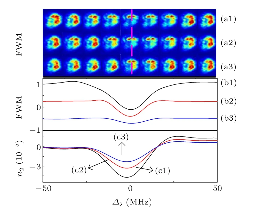
Fig.5. (a)Spatial images of the four-wave mixing signal with a scanning frequency detuning ∆2 range of −50 MHz to 50 MHz,an E1 power of 1.5 mW,and dressing field intensities of (a1) 30 mW, (a2) 20 mW, and (a3) 10 mW,respectively. (b)Spectra of the four-wave mixing with a scanning frequency detuning ∆2 range of −50 MHz to 50 MHz and dressing field intensities of(b1)30 mW,(b2)20 mW,and(b3)10 mW,respectively.(c)Nonlinear refractive index variation for a scanning frequency detuning ∆2 range of −50 MHz to 50 MHz and dressing field intensities of (c1) 30 mW, (c2) 20 mW, and(c3)10 mW,respectively. The power of E3 is 15 mW,and the power of E′3 is 15 mW.
Based on Figs. 5(a)–5(c) it can be seen that the external dressing field has a modulating effect on the nonlinear Kerr refractive index. Furthermore, it may also modulate the intensity and spatial spot area of the four-wave mixing signal.When the intensity of the external dressing field is larger, the nonlinear Kerr refractive index changes at a faster rate, and the nonlinear modulating effect of the four-wave mixing signal becomes stronger. Conversely, when the intensity of the external dressing field is smaller,the nonlinear Kerr refractive index changes more slowly, and the modulating effect of the four-wave mixing signal becomes weaker.
5. Conclusion
In summary, we have presented a theoretical and experimental study of the spatial image and spectral signal evolution patterns of the probe transmission and the four-wave mixing signal based on an inverted Y-type four-energy level atomic system by changing the adjustable parameters of the light field. The refractive index of the medium was modulated by the nonlinear Kerr effect of the interaction between the light field and the atomic medium. In addition,the nonlinear phase shift of the probe transmission and the four-wave mixing signal was modulated. Spatial shifting and splitting patterns of the probe transmission and the four-wave mixing signals were obtained by manipulating the light fields. In this process, it was observed that frequency detuning and the power of the light fields play a decisive role in the spatial image change of the probe transmission and four-wave mixing signals. These modulating patterns provide experimental technology support for all-optical communications and open up potential research prospects for nonlinear optical communications networks.
Acknowledgments
Project supported by the National Natural Science Foundation of China (Grant No. 61705182) and the Natural Science Foundation of Shaanxi Province, China (Grant No.2017JQ6024).
杂志排行

Chinese Physics B的其它文章
- Editorial:Celebrating the 30 Wonderful Year Journey of Chinese Physics B
- Attosecond spectroscopy for filming the ultrafast movies of atoms,molecules and solids
- Advances of phononics in 20122022
- A sport and a pastime: Model design and computation in quantum many-body systems
- Molecular beam epitaxy growth of quantum devices
- Single-molecular methodologies for the physical biology of protein machines