Multifunctional flexible optical waveguide sensor: on the bioinspiration for ultrasensitive sensors development
2022-12-12ArnaldoLealJuniorLeticiaAvellarVitorinoBiaziSimoneSoaresAnselmoFrizeraandCarlosMarques
Arnaldo Leal-Junior, Leticia Avellar, Vitorino Biazi,M. Simone Soares, Anselmo Frizera and Carlos Marques*
Keywords: optical sensors; optical waveguides; bioinspired design; multifunctional structures; wearable sensors
Introduction
The Internet of Things (IoT) is a growing technology that consists of the interconnection of heterogeneous devices through the Internet without human intervention1.Some requirements of IoT implementation involve massive connectivity, high privacy and security, ultrahigh reliability, and ultra-low latency2. To satisfy these requirements, several wireless technologies have been used in IoT applications, including Wi-Fi, Bluetooth,and different generations of mobile networks(2G/3G/4G)3. However, they are not fully optimized for IoT applications1. The growth of 5G networks is expected to solve challenges faced by other wireless technologies already used in IoT, especially in terms of enhanced mobile broadband, ultra-reliable and low-latency communications, and massive machine-type communications4. To that extent, many technologies were developed to achieve systems with low power consumption,high connectivity, and reliability in conjunction with micro-dimensions5.
The advances in material processing and microfabrication have enabled the continuous enhancement of the compactness and capabilities of photonic devices6,7. In addition, 3D printing technologies also play an important role in device fabrication, where different nanocomposites are proposed8. As an important application of such miniaturized devices, the development of different photonic waveguides leads to a new generation of labon-a-chip sensing applications9as well as novel miniaturized devices6. Such new developments hold a relation with the so-called micro-opto-electro-mechanical systems (MOEMS), derived from the well-known microelectro-mechanical systems (MEMS) with the addition of optical components10.
The MOEMS approach is applied on the development of different sensors, especially the accelerometers and displacement sensors, as summarized in Lu et al.11. In the current development of MOEMS sensors, a common approach is to use the optomechanical interaction for the sensor transduction mechanism using different optical sensors approaches, including interferometers12, fiber Bragg gratings13, photonic crystal approaches8, and intensity variation-based sensors11. In these approaches,there is the development of a mechanical structure to embed the optical fiber (or any optical waveguide) for the sensor transduction11. However, the advances in material processing and characterization enable the development of multifunctional structures, where the materials have multiple functions in the system such as structural elements able to transmit electrical or optical signals14. In this case, there is a combination of structural and opto/electronic designs to achieve signal transmission and structural functionalities. The multifunctional nature of the devices leads to enhanced portability and compactness of the devices, which find important applications especially in healthcare by means of integrated assistive devices15and clothing-integrated wearable sensors16,17. In the development of optimized structures,a straightforward approach in many cases is to observe the structures available in the nature subjected to many years of evolution and adaptation18. The bioinspired and biomimetic designs have been a focus of research for many years in different areas, including sensor development19. Among these bioinspired structures, the spider web (orb web) structure is of great interest in the scientific community due to its multifunctional nature for prey capturing and vibrations transmission20,21, which can be used in multifunctional structures for vibration,displacement, and pressure sensing.
This paper presents a highly sensitive photonic flexible waveguide-based sensors using MOEMS technology with customizable, tunable, and affordable approaches.The so-called bioinspired multifunctional flexible optical sensor (BioMFOS) has a bioinspired shape in which a spider web-like structure was designed to achieve an ultrahigh sensitivity for different with μN resolution in force assessment and sub-millimeter spatial resolution for force location sensing. In addition, a proof mass and the light source are integrated into the device to measure the 3D orientation of the proposed flexible sensor. We focus the sensor design on the optomechanical interaction, where the materials used on the orb web-like structure are analyzed in terms of their optical and mechanical responses. In this case, biocompatible and transparent resins are employed in the sensor design. However, these polymer resins are viscoelastic materials that present an elastic and a viscous response22, which result not only in a spring behavior but also in the damping of an oscillatory load. Thus, another contribution of this work is on a new method of analyzing the so-called multifunctional materials in which the resins are used as flexible photonic waveguides and, at the same time, as structural elements for a mass-spring-damper system used on the proposed 3D orientation sensor. Then, as another contribution of this work, the millimeter-scale 3D orientation sensor is applied on two protocols of movement analysis,where the 3D orientation, as well as movement classification, is performed with a single device integrated into clothing and accessories.
Materials and methods
BioMFOS bioinspired design and fabrication
The proposed sensor has a bioinspired structure in which a spider (orb) web-like shape was designed. The structure is shown in Fig. 1, where it is possible to verify the frame structure with radial and frame elements. It is worth mentioning that the center of the structure has a hole for the position of batteries and the micro lightemitting diode (μLED), resulting in a mooring sector, as discussed in Soler and Zaera23. The bioinspiration on the spider webs to the sensor development is related to their multifunctional characteristics of this shape, where there is the combination of mechanical resistance, shock absorption, and vibration transmission performance24. The mechanical model of the proposed structure is also presented in Fig. 1, where the elements are modeled as a combination of mass (especially the proof mass on the center), springs and dampers. In this case, we consider that each radial element acts as a spring-damper element connected to the proof mass in the center of the structure. The structural (and optical) elements of the proposed design are polymers resins. Such materials have viscoelastic responses, i.e, elastic and viscous components on the materials’ responses, where a suitable method of modelling them is through Maxwell’s model, which considers the viscoelastic response of the materials as combinations of spring and damper25. Thus, the stiffness and damping of the structural elements are estimated from the resin’s viscoelastic characterization. In this structural arrangement, the displacement of the mass in the center of the structure provides a proportional displacement in the frame along the radial elements. An analytical evaluation of this structure was performed based on the mechanical model shown in Figure 1, where the goal was to obtain the displacement in one end of the structure when the proof mass is under displacement at different positions. Equations (1) and (2) show the displacement in point A (see Fig. 1) when the mass is subjected to forces atz-axis (Fz) andy-axis (Fy). The detailed modeling of the proposed structure is depicted in Supplementary information.
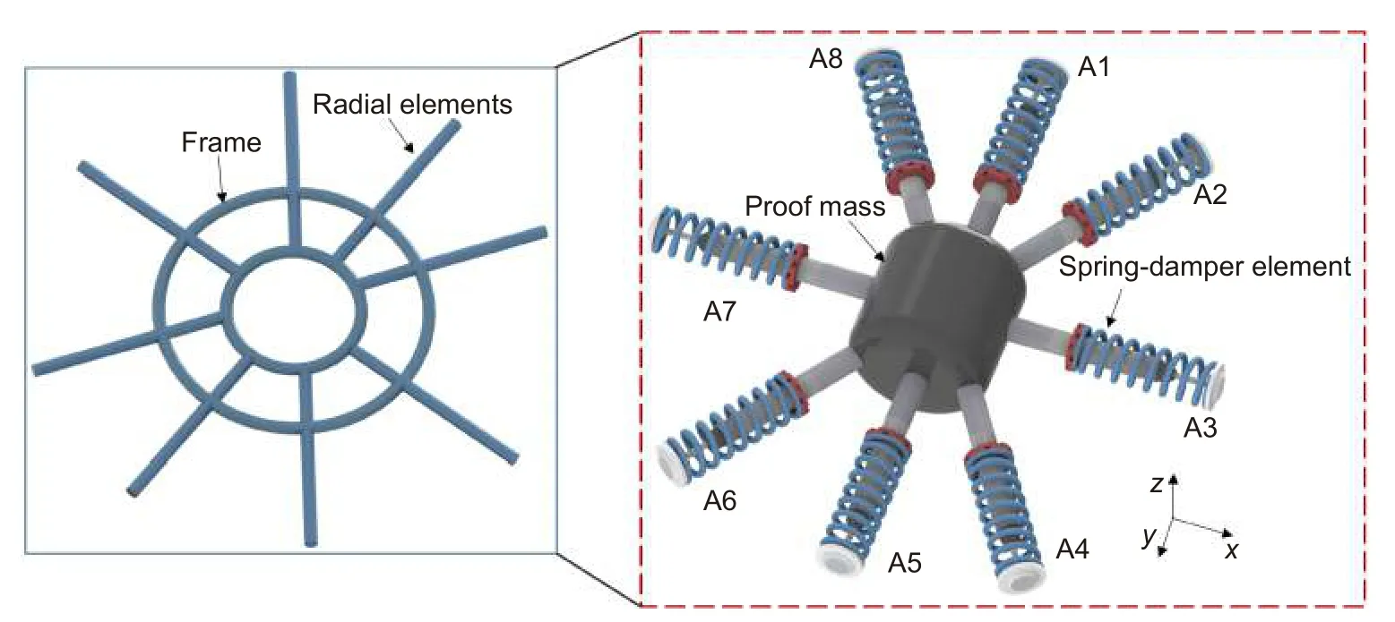
Fig. 1 | Schematic representation of the sensor structure with the frame and radial elements. Figure also shows the mechanical representation of the structure with a mass on the center.

wheremeis the mass of the center structure (proof mass),cis the damping on the structure,kaandktare the stiffness of the radial elements in parallel and transverse planes, respectively.
The functionalities of the orb web in the nature are due to not only its shape but also to the employed material, as spider silk has favorable mechanical properties, especially its high strain limits higher than 25%26. In the proposed sensor, the material plays an additional role on the device due to its multifunctional nature, where the selected polymer is used as a structural element for the mechanical transduction in the proposed design and acts as a waveguide for the optical signal transmission. Thus,the selected polymer should be flexible and transparent,combining optical and mechanical properties. In this case, the core-cladding structure is designed for the total internal reflection of the light propagating in the waveguide. For this reason, polydimethylsiloxane (PDMS)and photocurable resins are used on the core and cladding of the proposed multifunctional structure, where the PDMS is used as cladding due to its lower refractive index (around 1.43 in the visible wavelength range) when compared with the photocurable resin (about 1.50).
The optical transmission properties of the employed materials are analyzed through the spectrophotometry at visible and 850 nm bands. For the samples’ preparation,rectangular (10 mm × 20 mm) samples with 2 mm thickness were fabricated with both materials. For the PDMS resin development, the monomer and curing agent were added in the 10:1 proportion, whereas the photocurable resin was added in a container with the same dimensions of the rectangular samples, and an ultraviolet (UV)lamp is used for the resin’s curing for 40 seconds to ensure full curing of the resin. The UV lamp can be used on the curing of different types of photocurable resins,where the combination of different types of resins can lead to a combination/customization of optical and mechanical properties. In this case, the UV lamp used was UTarget-365 (AMS Technologies, Germany) with 1400 mW/cm2radiance at 365 nm. As the proposed sensor design has a multifunctional behavior, the mechanical properties of the resins are also key parameters on the structural performance of the bioinspired design.Thus, the mechanical properties, namely the strain limits and Young’s modulus, are estimated through the stress-strain cycles following ISO 527-1:2019 standard using a universal testing machine. In addition, the viscoelastic behavior of the polymers is analyzed via dynamic mechanical analysis (DMA) in which an oscillatory load is applied on the samples with controlled temperature, frequency, and amplitude. In this case, the dynamic Young’s modulus is evaluated, which comprises of the storage modulus (related to the elastic component of the response) and the loss modulus (related to the viscous component of the viscoelastic response). The samples are submitted to different temperature conditions, where the dynamic Young’s modulus is analyzed for each condition and the materials’ damping can be inferred from the loss factor of the material, which is the ratio between the storage and loss moduli.
For the BioMFOS fabrication, the different features of the integrated device are considered and are summarized in Fig. 2. The structure is fabricated with a photocurable resin as the core of the multifunctional waveguide using the stereolithography 3D printing (with a 360 nm light source) approach with the structure presented in Fig. 2(a) and a circular cross-section of 0.5 mm diameter. The left part of Fig. 2(a) shows the schematic representation of procedure of stereolithography 3D printing, where there is a container filled with UV-curable resin with a transparent bottom, which is submitted to an UV lamp projection with the shape of the waveguide’s cross-section as shown in Fig. 2(a) inset. Therefore, the UV resin is cured with the shape of the waveguide. Then, the core structure is placed inside a container filled with the PDMS resin, on both sides, as also shown in Fig. 2(a). The thermo-cure is performed inside a climatic chamber at 60 °C for 24 hours.
The device is also comprised of two silver oxide batteries (1.5 V each) connected to a μLED both positioned on the center of the structure, as shown in Fig. 2(b). The μLED has an output power of about 0.5 mW and light couple between the light source and the waveguide occurs from the bottom of the structure to each radial element with around 0.1 mm of distance between the μLED and the waveguide. Thus, there is an electro-optic conversion in this assembly, where the electrical signal is converted into an optical signal transmitted through the transparent bioinspired structure. Furthermore, the battery-LED assembly is encapsulated into a PDMS resin layer that also connects them to the structure, which is used as the proof mass of the system. In this case, the optical signal is transmitted from the light source to the structure subjected to different pressures or displacements on the proof mass/structure. These mechanical disturbances in the structure lead to different strains in the waveguide, which results in differences in the optical signal transmission due to the opto-mechanic interaction. The system weighs around 0.8 g, which is an ultralightweight system with important applications on wearable and micro-devices. As the last step on the sensor integration, there is the conversion of the optical signal(with the opto-mechanic interaction) to electrical signals to be transmitted or visualized. To that extent, each radial element can be connected to a micro-photodetector.However, if a high number of photodetectors is used,there would be higher energy consumption, leading to the necessity of including a higher number of batteries.Thus, there is a tradeoff between the number of detectors (directly related to the accuracy) and the energy consumption. As an alternative to mitigate this tradeoff, different dyes can be applied to each radial element, which is connected to a spectrometer, where each radial element (or group of radial elements) has a peak on the transmitted (visible) spectrum related to its dye color.

Fig. 2 | (a) Schematic representation of the core/cladding fabrication steps. (b) Representation of the batteries and μLED assembly in the structure, which is used as the light source of the optical system and proof mass of the structural design. Figure also shows a photograph of the BioMFOS.
Experimental analysis
The material characterizations, performed by means of spectrophotometry, tensile tests, and DMA were previously discussed. In addition to these characterizations,the sensor performance is analyzed in two scenarios. In the first scenario, the force sensitivity is analyzed in a PDMS matrix, with 4 radial elements connected to the photodetector by applying a 2.5 mN force at different positions on the sensor structure. The variations on the transmitted optical power of each radial element are analyzed, where it is possible to estimate the amplitude and position of the force (or pressure) application using the optical signals transmitted in the radial elements.
Then, the possibility of measuring the 3D orientation of the sensor structure is assessed by positioning the bioinspired structure at different orientations on thex,y,andzplanes. The proposed sensor is compared with an inertial measurement unit (IMU) Xsens MTi-1 comprised of a three-axis accelerometer, gyroscope, and magnetometer. The orientation on Euler angles obtained from the IMU is correlated to the optical signal variations. In this case, we used 3 radial elements with 120° separation between them. All tests are performed in room temperature and relative humidity conditions.
After the initial characterizations, the proposed device is applied on movement analysis. The first application of this sensor is on the hand and finger movements using only one structural element, where the BioMFOS is placed on the top of the hand of a volunteer, which is asked to place the palm of the hand at different orientations. Then, the user is asked to perform some finger movements (open hand, one, two, three and four fingers raised, and closed hand) with the sensor positioned on the same region (i.e., top of the hand). It is expected that the sensor is capable of detecting slight orientation variations in the hand for each condition of finger position due to the high sensitivity and resolution of the BioMFOS, where there is a possibility that small displacements variations in the hand (due to the fingers positions) can be detected by the radial elements of the proposed device. In another application, the sensor is integrated into clothing to track the 3D orientation of the user’s trunk. For this reason, the volunteer is asked to perform different movements (chest lifting and retraction, and right and left lateral movements) that result in different trunk orientations measured by the BioMFOS.Finally, the high sensitivity on the orientation sensing of the proposed device is used on the respiration rate assessment using the clothing-integrated sensor. The user is asked to standing still for 30 seconds with the breaths counted. As the breath cycles have cyclic responses, an FFT is applied on the sensors' responses in which the frequency peak is related to the respiration rate. All experiments were performed in accordance with the guidelines of the national health council with the protocols approved by the Research Ethics Committee through the National Commission in Research Ethics-CONEP-(Certificate of Presentation for Ethical Appreciation-CAAE: 41368820.3.0000.5542). Principal components analysis (PCA) was used in the signal processing in which the data is presented in a new coordinate system by using linear transformations and is a widely used technique for dimensionality reduction and as preprocessing for clustering techniques27.
Results and discussion
The materials’ optical and mechanical responses are presented in Fig. 3, where the transmittance (in the visible wavelength range) and tensile tests are shown for the PDMS and UV-curable resins. In the optical response,the transmittance obtained from the spectrophotometer in the wavelength range from 400 nm to 700 nm, where it is possible to observe a higher transmittance of the PDMS curve (59.82% ± 3.51%, considering 450 nm to 700 nm), which is higher than the one from the UV-curable resin (32.34% ± 2.00%, considering 450 nm to 700 nm). However, it is worth noting that the PDMS has a smaller refractive index (1.43) than the UV-curable resin(1.50), which motivated its use as the cladding of the waveguide. Nevertheless, both optical materials have only minor transmittance variations within the analyzed wavelength range in which maximum transmittance variations of 15.43% and 6.91% (for the wavelength range from 450 nm to 700 nm) were found for the PDMS and UV-curable resin, respectively. The optical loss of the proposed waveguide is below 0.7 dB/mm.

Fig. 3 | Optical and mechanical characterizations of the resins (photocurable and PDMS resins). Transmittance spectra, Stress-strain curves, and DMA results are presented.
The stress-strain curves of each material are presented in Fig. 3, where it is possible to infer the mechanical properties of the materials used on the bioinspired structure. Such mechanical properties analysis, in conjunction with the optical properties, are crucial for the multifunctional features of the proposed BioMFOS. The tensile tests indicated a high strain limit of 42% for the PDMS and 2.8% for the UV-curable resin. In addition,the Young’s modulus of each material is estimated from the stress and strain variations within the elastic region of the material. In this case, the UV-curable resin has a Young’s modulus of 1.23 GPa, whereas the PDMS has 0.43 MPa Young’s modulus. Considering the orb web structure, spider silk plays an important role in the structural device23. If the materials used on the bioinspired device are compared with the spider silk, both spider silk and UV-curable resin have similar mechanical properties, especially on Young’s modulus 1.8 GPa of the spider silk28and 1.23 GPa of the resin. The PDMS is a highly flexible material with a low Young’s modulus, which makes it a suitable matrix for the incorporation of the proof mass, namely the battery assembly. Thus, small pressures/forces lead to high deflections on the PDMS region, which increases the sensor sensitivity. Furthermore, the dynamic response of the material is presented in Fig. 3 to evaluate the influence of the frequency of oscillatory movement on the storage modulus and loss factor (ratio between the storage and loss moduli). The rectangles in the DMA results are related to the stable regions on the storage modulus variation, where there are no significant variations on the storage modulus, such variations can affect the sensor’s performance. In this case, we observe stable responses of the storage modulus and loss modulus for a frequency interval between 0.1 Hz and 50 Hz with another stable region in the range of 70 Hz to 150 Hz, which indicate the feasibility of the proposed device on the movement assessment in this frequency range. Such range is aligned with the frequency requirements for biomedical and biomechanical applications11in which the proposed device is applied (for movement analysis and classification).
The highly flexible materials used on the design also enable the possibility of force sensing of the bioinspired sensor. In this case, the force applied at different locations of the structure can be detected through the optical signal variation on the sensor. Figure 4 shows the optical responses of four radial elements when the structure is subjected to force applied at different locations. As the variation of displacement on the proof leads to the variation of all radial elements, the force sensitivities of the elements are estimated from a loading directly applied on each element. The sensor responses indicated in Fig. 4 shows the possibility of measuring forces applied on the structure, with the sensitivities of each element indicated in Fig. 4. According to the sensitivities of the sensors and the noise floor, forces are in the order of 13.28 μN. Such high sensitivity opens a wide range of critical applications of the proposed device, including nanotechnology,nanofabrication, and so on. The forces applied in different positions of the structure lead to variations in the sensors' responses when each location is analyzed. The different responses are related to the differences in the strain or stress transmitted to each radial element, as four elements are analyzed, the fusion or comparative analysis of the four responses can indicate the location of the force application along the structure. For this reason,it is possible to perform a shape reconstruction of the structural device when subjected to different loading conditions using the optical responses of the radial elements. The spatial resolution is estimated from the sensitivity of the combined analysis in all radial elements for loadings applied at different positions on the sensing elements. From the sensitivity and the noise floor analysis,it is possible to estimate the spatial resolution, i.e., the minimum variation on the position of the loading application. The analysis of the sensors' responses at each force location in conjunction with the sensors’ noise and sensitivities indicated a spatial resolution of 0.02 mm on the location estimation, which is lower than the resolution of other optical systems with bulk design and higher cost equipment. It is worth noting that the spatial resolution can be improved if a higher number of radial elements is used. Thus, the low cost and relative simplicity of the signal processing open new avenues on shape reconstruction approaches. In addition, the proposed device presents a stability on operation, since there was not a variation on sensor’s sensitivity and response time on the tests during a three weeks period. Nevertheless,the core and cladding materials of the proposed waveguide are made of polymers, which can present an ageing effect, resulting in physical variations on the materials29. Such variations can result in different optical and mechanical properties that can affect the sensors responses. Thus, for a long period of usage (typically in the order of months), the sensor should be recalibrated, such recalibration necessity is a common trait in many sensors. However, for the 3D orientation/displacement sensing, a protective cover is added in the sensor to isolate it from mechanical disturbances on the sensor, since these disturbances can influence the sensors’ responses.
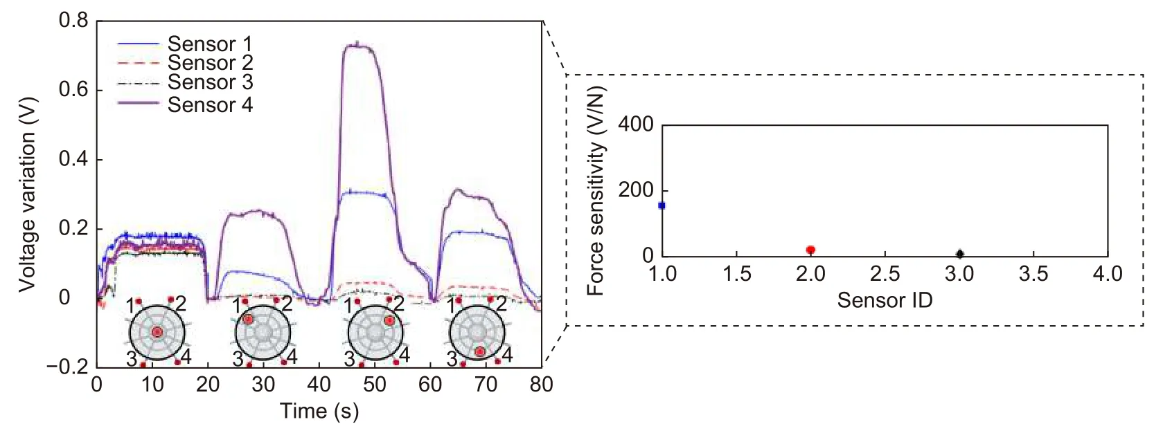
Fig. 4 | Transmitted optical power (converted into voltage in the photodetector unit) as a function of the applied force in different positions of the PDMS matrix. Figure also shows the force sensitivity of the sensors.
Figure 5 presents the optical signal variations of three radial elements under different orientation conditions,the results are compared with the ones of an IMU to demonstrate the feasibility of the approach and obtain an accurate representation of the sensors' responses at the predefined rotation planes, namely roll (aroundx-axis),pitch (aroundy-axis) and yaw (aroundz-axis). The positions of the radial elements used in this analysis are presented in Fig. 5(a) inset. The comparison with the IMU results indicates the suitability of the proposed bioinspired sensor, where a correlation coefficient of 0.932 ± 0.042 was obtained in the comparison of both responses. The high correlation between both approaches motivated the use of the BioMFOS on movement analysis and classification applications. Thus, the first application is on the finger position recognition using only one sensor positioned on the top of the user’s hand. The sensors' variations as a function of the finger positions are presented in Fig. 5, where it is possible to observe the influence on the slightly variations on the hand orientation (as different finger positions are performed), which are tracked by the BioMFOS.
Therefore, it is possible to classify or estimate the fingers positions as a function of sensors responses using sensor fusion or machine learning techniques. The transmitted optical power of each sensor for the different finger positions is also presented in Fig. 5, where it is possible to observe that at least one response varies with the finger position, resulting in the possibility of identification by using the combinations of the responses of the axial elements. It is also worth mentioning that a higher number of radial elements can be used for higher sensitivity or accuracy on the finger position classification. The proposed approach has the advantage of using only one sensor structure when compared with contact approaches, where additional sensor elements are placed at each finger, resulting in a larger system with the possibility of higher power consumption, complexity on fabrication, and implementation. Such approach results in a transparent system for the user, as it does not need additional accessories and is not directly connected to the user’s joints, thus provides comfort for the user, which is directly related to the device usability.

Fig. 5 | (a) Comparison between the BioMFOS responses (of three radial elements) and IMU for different positions/orientations in 3D plane. The directions of the orientation planes (roll, pitch, and yaw) are also shown. Figure inset shows the positions of the radial elements used in these tests. (b) Optical signal variation of 3 radial elements (sensors 1 to 3) as a function of the finger position, markers and bars represent the mean and standard deviation of the tests, respectively.

Fig. 6 | (a) Respiration rate assessment using the BioMFOS. (b) Trunk position classification using the BioMFOS integrated into clothing and PCA results for each trunk position.
In the last application of the proposed device, the sensor is integrated into the clothing as shown in Fig. 6.In this case, the user (with the clothing-integrated sensor) is asked to stand still and, then, perform trunk movements at different orientations, where the 3D orientation and the respiration rate are measured by the sensor. Figure 6 also shows the respiration rate of the user estimated by the sensor. The respiration rate is estimated from the frequency response of the sensor,where an FFT is applied on the optical power in the time domain obtained from a radial element. As respiration is a cyclic event, the frequency peak in the response is related to the respiration rate of the user. In the first experiment, the respiration rate was 12 breaths per minute,manually counted and well-aligned with the respiration rate of an adult at rest30. Then, another experiment was performed with a fast respiration rate, with 24 breaths per minute. The frequency peak on the sensor response is 0.2 Hz (see Fig. 6), which represents exactly 12 cycles per minute (when the frequency in Hz is converted). The results indicate the suitability of the proposed device as an ultrasensitive, lightweight, and clothing-embedded optical waveguide for respiration monitoring. Thus, the sensor can be employed on remote healthcare well aligned with the IoT requirements of low energy consumption and reliable miniaturized sensor.
The sensor positioned on the user’s trunk (via the clothing-integrated device) can also detect the trunk’s orientation due to its highly sensitive operation. The user performs predefined movements resulting in variations at the sensor orientation. The results obtained in the PCA also show the suitability of the proposed device on activity classification or clusterization, where the sensors are able to detect daily activities as well as rehabilitation movements. In this case, the principal components shown in Fig. 6(b) indicate the linear combinations of the sensors responses that lead to the highest correlation of the results as a preprocessing of a clustering technique. The principal components 1 and 2 represent 99.9% of all variability, where principal component 1 represents 67.3% of the variability, whereas principal component 2 is related to 32.6% of all variability. Thus,the analysis of different radial elements can be used in the assessment of the trunk 3D orientation. This advantageous feature results in a compact and fully integrated sensor employed on movement analysis and remote health monitoring of different users, including on the continuous assessment of elderly with fall risk as well as a device for activity monitoring in different healthy or injured subjects.
Conclusions
This paper presented the development of a bioinspired optical waveguide sensor for 3D orientation monitoring and shape reconstruction with ultrahigh sensitivity. The sensor structure is inspired on orb-webs in which primary and secondary frames are connected to radial elements with a proof mass, comprised of the system’s batteries and light source, in the center of the device. The device has a multifunctional operation, as a structural element and optical transmission medium. Thus, the materials’ optical and mechanical properties were analyzed in order to obtain transparent and highly flexible material through transmittance, stress-strain curves, and dynamic mechanical analyses, enabling the development of a system with both structural and optical signal transmission properties. In the shape reconstruction analysis,a force is applied on a PDMS matrix at the center of the structure and on different positions of the structure,whereas the optical signals of the radial elements are analyzed as a function of the applied force intensity and location. The results show the possibility of measuring micro forces (with μN) and the shape reconstruction of the forces applied on the proposed sensor with sub-millimeter spatial resolution.
Therefore, the force assessment using this structure leads to two conclusions. i) It is possible to use this device on the shape reconstruction in micro (or nano)devices in different nanotechnology applications. ii)Transverse forces or pressures applied in the top plane of the device can influence the sensor’s response in applications of 3D orientation assessment. Thus, a protective cover, added to the sensor structure, was used on the orientation assessment at different planes. The sensor response was compared with a gold standard IMU, where a high correlation coefficient of 0.932 ± 0.042 between both sensors was found. Then, the sensor was used on movement recognition and analysis as well as vital signs monitoring in which the sensor was integrated (or placed) at the user’s hand for finger movement recognition and at the clothing for trunk movement analysis as well as respiration rate assessment. The results show the possibility of analyzing different movements as well as the vital signals using a single, low cost, ultrasensitive,and highly lightweight device (sub-gram mass). Therefore, the proposed device opens new avenues in many applications for biomedical, biomechanics, and micro/nanotechnology. In addition, it can provide new paradigms on the general precision-cost tradeoff, where the proposed device presents both high sensitivity and resolution associated with low interrogation, fabrication,and implementation costs. Future works include the development of multifarious applications for the device,where it can be used in fully transparent human-machine interface, tactile units for microdevices, biomechanical analysis, remote healthcare, and robotics/assistance devices teleoperation. It is also worth to mention that the proposed device can be functionalized for the detection of chemical compounds as well as immunosensing in biomedical and environmental monitoring.
Acknowledgements
This research is financed by FAPES (320/2020 and 84336650), CNPq(304049/2019-0 and 427054/2018-4) and Fundação para a Ciência e a Tecnologia (FCT) through the DigiAqua project - PTDC/EEIEEE/0415/2021. C. Marques acknowledges FCT through the CEECIND/00034/2018 (iFish project) and this work was developed within the scope of the project i3N, UIDB/50025/2020 & UIDP/50025/2020, financed by national funds through the FCT/MEC.
Author contributions
A. Leal-Junior proposed the methodology. A. Leal-Junior and C. Marques supervised the work. A. Leal-Junior and L. Avellar fabricated the samples and performed the experiments. V. Biazi performed the analytical models.A. Leal-Junior, M. S. Soares, A. Frizera and C. Marques analyzed and discussed the data. All authors commented on the manuscript and contributed to the paper writing and revisions.
Competing interests
The authors declare no competing financial interests.
Supplementary information
Supplementary information of this paper was uploaded in the submission.https://doi.org/10.29026/oea.2022.210098
杂志排行

Opto-Electronic Advances的其它文章
- Label-free trace detection of bio-molecules by liquid-interface assisted surface-enhanced Raman scattering using a microfluidic chip
- High performance integrated photonic circuit based on inverse design method
- A review and a statistical analysis of porosity in metals additively manufactured by laser powder bed fusion