Effect of interface anisotropy on tilted growth of eutectics:A phase field study
2022-10-26MeiRongJiang姜美荣JunJieLi李俊杰ZhiJunWang王志军andJinChengWang王锦程
Mei-Rong Jiang(姜美荣), Jun-Jie Li(李俊杰), Zhi-Jun Wang(王志军), and Jin-Cheng Wang(王锦程)
State Key Laboratory of Solidification Processing,Northwestern Polytechnical University,Xi’an 710072,China
Keywords: tilted eutectics,interfacial energy anisotropy,multi-phase field model
1. Introduction
Tilted eutectic,[1–8]in which the growth orientation of eutectics deviates from the direction of the imposed temperature gradient (G) during directional solidification, is a common microstructure for eutectic alloys. As is well known,the mechanical properties of eutectic materials are closely related to its growth orientation. Thus, deep understanding the tilted growth of eutectic is very important for the better control of microstructure and improvement of properties.
Like the tilted growth of dendritic arrays,[9–14]the growth of eutectic is governed by the temperature field, concentration field, and preferred crystal orientation of solidified phase. However, owing to the characteristics of the cooperative growth, the mixed solute diffusion near the front of solid–liquid interfaces, and the force balance at triple points,the tilted growth of eutectic is much more complex than that of dendrite arrays. In particular, typical eutectic patterns are composed of two solid phases with different preferred crystal orientations, which makes the tilted growth of eutectic more flexible and thus more complex in turn.
Up to now,many efforts have been made to elucidate the formation of tilted eutectics.Several experimental and theoretical studies[3,4,6,15–21]suggested that the tilted growth of eutectic lamellae is dependent on the solidification dynamic behavior. It was well demonstrated that the solidification dynamic behavior often relies on initial conditions,[22,23]in which the initial lamellae spacingλ0is an important factor that influences the dynamics behavior. Whenλ0>aλm, whereais a constant related to the solidification conditions andλmis the minimum undercooling spacing,[24]a homogeneous tilt bifurcation (a tilted periodic state) was observed.[6]And a paritybreaking transition from the symmetric state to a tilted state has also been observed for the liquid–solid interface front profile during the tilted growth of eutectics.[19]Although these reports presented some explanations on the formation of tilted eutectics,the effect of the anisotropic interface energy on tilted growth of eutectics was not taken into account.
With the development of eutectic solidification theory and research methods, the importance of interfacial energy anisotropy on tilted eutectics is well recognized.[7,25–34]From thein-situdirectional solidification experiments of transparent alloys, Caroliet al.[25]found that the tilted growth of lamellae and symmetry reflection of the solid–liquid interface front profile are broken,induced by interfacial energy anisotropies.Having made further theoretical analysis,they concluded that the anisotropy of solid–solid interface energy attempts to tilt lamellae into the orientation with the lowestα/βinterface energy,while the anisotropy of solid–liquid interface energy may modify the pinning angle forαphase andβphase at triple points. Thus,it can be assumed that the contribution of solid–solid interface energy anisotropy to eutectic growth is comparable to that of solid–liquid interface energy anisotropy. Akamatsuet al.[7]observed that the shape of solid–liquid interface in anisotropy-driven traveling lamellae patterns can be maintained to be approximately mirrorsymmetric by a modified directional solidification methodology called rotating directional solidification. To simplify the analysis, they further assumed that the shape of the solid–liquid interface is exactly symmetric; in other words, they omitted the effect of solid–liquid interface energy anisotropy on the formation of eutectics and concluded that the solid–solid interface anisotropy plays an important role in the forming of tilted eutectics.Based on Akamatsuet al.’s experimental results,Ghoshet al.[35–37]investigated the effect of solid–solid interface energy anisotropy on tilted growth of eutectics by using a multi-phase field model,and found that the anisotropy of solid–solid interphase energy can significantly affect the growth direction of eutectics. Tuet al.[38,39]further investigated the effect of solid–solid interphase energy anisotropy on lamellar eutectic morphology.They found that whenλ0is slightly larger thanλm,the lamellar morphology is mainly affected by the anisotropic interface energy of two solid phases, which results in the formation of a stable tilted lamellar pattern. However, whenλ0is significantly larger thanλm, the morphology is controlled by the variation ofλ0,resulting in the formation of an unstable mixed oscillation pattern.
In summary, the investigations mentioned above[7,25–39]have demonstrated that the anisotropic interface energy plays a vital role in the forming of tilted eutectics. However, the effect of the solid–liquid interface energy anisotropy on the tilted growth of eutectics is often ignored. As mentioned earlier by Caroliet al.,[25]the effect of solid–liquid interface energy anisotropy on the pinning angle forαphase andβphase at triple points during eutectic solidification have been confirmed. As is well known,a small variation of the pinning angle can significantly influence the local force balance at triple points,which will sharply influence microstructure evolution.Thus, further investigations of the effect of solid–liquid interface energy anisotropy on the formation of tilted eutectics are urgently needed. And the mutual interaction between the anisotropic solid–solid interface energy and the solid–liquid interfaces energy is also a challenge.
The phase field method,as a popular mesoscale numerical method,has been demonstrated as a powerful method in investigating microstructure evolution. Especially, the multiphase field model has been employed widely to study the eutectic solidification.[40–43]In this study,a multiphase field model was employed to investigate the effect and mechanism of solid–liquid interface energy anisotropy on tilted eutectics. Moreover,the interactions between solid–solid and solid–liquid interface energy anisotropy during the formation of tilted eutectics are also explored.
2. Methods
2.1. Phase field model
In binary eutectic solidification,two solid phases(αandβ) are simultaneously formed from the melt (L). Thus, the multi-phase field model proposed by Kimet al.[40,44]was employed to study the tilted growth of eutectics in this study.Three order parametersφi(i=1,2,3)were introduced to distinguish different phases during eutectic solidification:φ1=1,φ2=0,φ3=0 represents the liquid phase,φ1=0,φ2=1,φ3=0 andφ1=0,φ2=0,φ3=1 denote the bulk phase ofαandβ,respectively. And 0<φi(i=1,2,3)<1 indicates the interface.
A general free energy function description in this multiphase field model of a eutectic system includes the interfacial free energyfPand thermodynamic potentialfT,which can be written as

whereξis the Lagrange multiplier for the restriction condition conserving the sum of phase fields at random point in the system. According to the variational principle, the governing equation of the phase-field variable can be described as

whereT0is the initial solidification temperature,Gis the temperature gradient,andVis the pulling velocity.
2.2. Interfacial energy anisotropy
A two-fold symmetric interfacial energy anisotropy function[35–37]was used to characterize the effect of interfacial energy anisotropy on the formation of tilted eutectics. It can be expressed as

whereγdenotes the interface energy;γ0the average interface energy;δthe anisotropy strength:δis set to be 0.005 when interface energy is anisotropic,and 0.0 when interface energy is isotropic;θRis the rotation angle,which is defined as the angle between the preferred crystal axis and the direction ofG;θis the angle between the interface normal direction and thexaxis as shown in Fig. 1(a). Figure 1(b) shows the schematic definitions of simulation parameters used in the prensent study,where theyaxis is parallel to theG. The tilt angle(θt)is the angle between the direction of the lamellae growth and that of theGdirection. Here, the direction, from the center position of the bulk phase (αorβ) at the beginning of solidification to that at the ending of solidification,is defined as the eutectic growth direction. Thus,θtcan be easily measured as shown in Fig.2(a). The other parameters in Fig.1(b)will be described in Section 3.
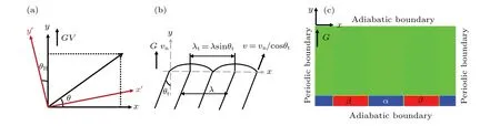
Fig.1. (a)Definition of θ and θR,(b)definitions of θt,(c)initial eutectic patterns and boundary conditions.
2.3. Parameters
In this study,we took a binary eutectic alloy with a symmetric phase diagram[36]for example,and all parameters used in this simulation are listed in Table 1.

Table 1. Parameters used in this simulation.
All simulations were performed in a domain of 800dx×100dxwith a regular grid. The initial eutectic patterns were set to be a periodic lamellae with a size of 10dx×100dxat the bottom of the simulation cell and paralleled to theG. Periodic boundary conditions were imposed in thex-axis direction,indicating an infinite periodic cycle of lamellae along thexaxis,while adiabatic boundary conditions were used in theydirection to ensure the solute conservation in this direction[40]as shown in Fig.1(c).
3. Results and discussion
3.1. Effect of interface energy anisotropy on tilted growth of eutectics
Figure 3 shows the evolution of eutectic morphologies under different interface energy conditions andθR=45°. The triple-point trajectories and the local force balance at the triple points, are also presented. From this figure, one can see that the lamellar growth direction aligns with the direction ofGwhen interface energy is isotropic. The pinning angle forαphase andβphase at the triple points are the same,i.e.,θα(61°)=θβ(61°). Here,the pinning angle is defined as the angle between the tangent of the solid–liquid interface and thexaxis at triple points. It can be determined from two steps:firstly calculating the value ofφy/φx;and then determining the pinning angle from the arctan functionθα=arctan(φαy/φαx),and the results are shown in Fig.2(b). The same pinning angles at triple points indicate that the solid–liquid interface ofL/αandL/βare symmetrical. Component force ofL/αinterfacial tension (σLα) andL/βinterfacial tension (σLβ) in thex-axis direction are equal, resulting in that the minimum interfacial tension of solid–solid interface is parallel to the direction ofG(yaxis). As is well known,during eutectic solidification, the lamellar growth direction always coincides with the direction of the minimum solid–solid interfacial tension.Therefore, the direction of eutectics growth aligns with that ofG, that is, non-tilted growth of lamellae occurs as shown in Fig. 3(a). However, when interface energy is anisotropic,the lamellar growth direction deviates from the direction ofGclearly. This indicates that the interface energy anisotropy has a significant effect on the lamellar growth direction.Generally,during eutectic solidification,when there exists anisotropic interface energy,the growth rates for different crystal planes are not the same,and the plane with a small interface energy will grow slow. The plane that grows fast will disappear,while the plane that grows slow is preserved in the crystal growth process. The difference in growth rate between different planes will induce the misalignment between the direction of minimum solid–solid interfacial tension and that ofG. Consequently,the tilted growth of lamellae is observed as shown in Figs.3(b)–3(d).And the force balance at triple points is shown at the bottom of Fig.3,where the dashed vectors represent the isotropic force vectors, the solid vectors are the anisotropic ones,andθα1,θβ1denote the deviation between the isotropic force vectors and the anisotropic ones. WhenL/αinterface energy is anisotropic, the force vector in the case of with anisotropy (the red solid arrow at the bottom of Fig. 3(b)) is different from that of without anisotropy (the red dashed arrow at the bottom of Fig. 3(b)). This variation of force vectorσL/αwill induce variations of other vectors(σL/β,σα/β)at triple points to maintain the force balance, resulting in the direction misalignment between the minimum solid–solid interfacial tension andGas shown at the bottom of Fig. 3(b).Similar processes are also observed whenL/βorβ/αinterface energy is anisotropic as shown by the force balance at bottom of Figs. 3(c) and 3(d), respectively. Moreover, it is found that the pinning angles forαphase andβphase at the triple points obviously are not the same even whenθtis small.This reveals that the symmetry of solid–liquid interface front profile is broken spontaneously when eutectic lamellae grows obliquely. However,noticeable discrepancies appear inθtunder different interfacial energy anisotropy conditions. From Figs.3(b)and 3(c),it can be seen clearly thatθt(1.4°)caused byL/αinterface energy anisotropy is smaller than that(6.4°)caused byL/βinterface energy anisotropy. This is because of different concentration distributions at the front ofL/αandL/β,which induces different driving forces in the cases ofαandβ. From Figs. 3(c) and 3(d), it can be observed thatθt(1.1°) caused byα/βinterface energy anisotropy is smaller than that (6.4°) caused byL/βinterface energy anisotropy.The reason for this phenomenon is that the direction deviation between the preferred orientation ofβand the direction ofGinduces the anisotropy of theL/βinterface energy, whereas the difference in the relative crystal orientation betweenαdirection andβdirection induces the anisotropy of theα/βinterface energy.

Fig. 3. Lamellar patterns, interface trajectories, and local force balance at triple points under different interfacial energy conditions, where a indicates preferred crystal orientation and v is growth rate of lamellae, showing (a) isotropic interface energy, (b) L/α interface energy anisotropy,(c)L/β interface energy anisotropy,and(d)α/β interphase energy anisotropy.
Figure 4 shows the curve ofθtversus θRunder different conditions of interfacial energy anisotropies. It is obvious that the whole trend of variation ofθtwithθRis almost the same when the interface energy is anisotropic,i.e. θtincreases initially and then decreases with the increase ofθR.However,obvious difference in variation trend between different anisotropic interface energy are also observed. When the solid–liquid(L/α,orL/β,orL/αandL/β)interface energy is anisotropic andθRis small,a very smallθtis observed. The preferred lamellae orientation deviates slightly from the direction ofG,resulting in small variations of the pinning angle for bothαphase andβphase at triple points. These small variations of the pining angle further result in a small deviation of the direction of minimum solid–solid interfacial tension from the direction ofG.On the contrary,a largeθtis observed whenα/βinterface energy is anisotropic andθRis small. In this case,the relative difference in crystal orientation between two solid phases is small.However,the preferred orientation direction ofα(aα)andβ(aβ)are the same,i.e.,all the preferred orientations are leftward as shown in Fig.5(a),indicating thataαandaβcan promote the tilted growth of lamellae.With the increase ofθR,θtincreases gradually,whether there exists interface energy anisotropy of solid–liquid or that of solid–solid,but the trend of its increase with solid–liquid interface energy anisotropy is obviously slower than with solid–solid interface energy anisotropy. WhenθRis large and solid–liquid interface energy is anisotropic, a largeθtis found. The preferred orientation of lamellae greatly deviates from the direction ofG, resulting in large variations of pinning angle forαphase andβphase at triple points,thus inducing a largeθtby maintaining the local force balance. In contrast, a smallθtis observed when solid–solid interface energy is anisotropic andθRis large. The relative difference in crystal orientation betweenαandβis very large. If the preferred orientation ofα(aα)remains unchanged, the direction ofaβchanges from left to right,and the preferred orientation ofaαandaβare opposite as shown in Fig. 5(b). Owing to the coupled growth of the two eutectic phases during solidification,the growth direction of eutectics tends to be parallel to the direction ofG. Similarly, whenθRis very large,θtis very small or even nearly 0°, with a solid–solid interface energy anisotropic. Whereas,when the solid–liquid interface energy is anisotropic andθRis very large,the preferred orientation of lamellae trends to be perpendicular to the direction ofG. Theoretically,θtshould be very large, but largeθtmust match largeθα1andθβ1to keep the force balance at triple points. It is a common fact that large angle variation needs larger energy than small one at triple point. If theθtis very large, the stable state cannot be obtained easily during solidification. Thus,θtwill decrease withθRincreasing further after achieving the maximum tilt angle.


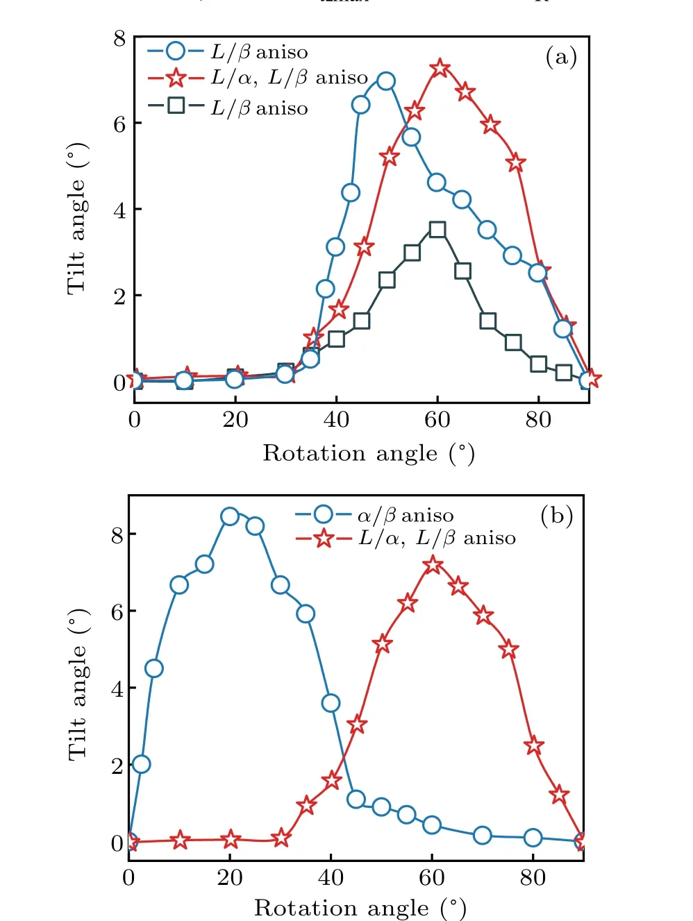
Fig. 4. (a) Curves of θR versus θt with different solid–liquid (L/α, L/β,or L/α and L/β)interface energy anisotropy(aniso), and(b)curves of θR versus θt with solid–liquid(L/α and L/β)interface energy anisotropy and α/β interface energy anisotropy.

Fig.5. Phase-field patterns and schematics of crystal orientation of two-solid phases with different rotation angles: (a)θR=10° and(b)θR=60°.
3.2. Tilted growth with both anisotropies of solid–liquid and solid–solid interface energy
Figure 6 shows the eutectic patterns against rotation angle when bothL/α,L/β, andα/βinterface energies are anisotropic. It can be found that asθRincreases, the growth direction of eutectic lamellae gradually deviates from the direction ofG,i.e.,θtincreases gradually. However, with the further increase ofθR, the growth of lamellae changes from tilted to non-tilted growth. In addition, whenθR=20°, the solid–solid interphase is rough,i.e., a small disturbance appears. Through the stable growth rate of lamellae and concentration distribution at the front of the solid–liquid interface,it is demonstrated that this disturbance of the solid–solid interphase is not induced by the instable growth of eutectic. Thus,a conclusion can be obtained that anisotropic interface energy may induce a non-smooth solid–solid interface. This may result from a small adjustment of interlamellar spacing caused by the anisotropic force balance at triple point.
Figure 7 shows the comparison between the simulated and the measured curves ofθRversus θt. It can be seen that whenL/α,L/β, andα/βinterface energies are anisotropic,theθRcorresponding to theθtmaxfrom phase feild simulations is approximately 30°,which accord well with the experimentalresults byAkamatsuetal.[7]However,theθRcorresponding totheθtmaxis20°when onlyα/βinterface energy is anisotropic, whereas it is 60°when bothL/αandL/βinterface energies are anisotropic.This reveals that the solid–liquid(L/α,L/β)and solid–solid(α/β)play vital roles in the forming of tilted eutectics. Moreover, whenL/α,L/β, andα/βinterface energies are anisotropic andθRis larger than 60°,θtis small, which is the same as the case ofα/βinterface energy anisotropy, indicating that the solid–solid interfacial energy anisotropy plays an important role in the tilted growth of lamellae,while the anisotropy of solid–liquid interface energy plays a less important role. However, the latter anisotropies can still influence theθRcorresponding to theθtmaxby affecting the local force balance at triple point.WhenL/α,L/β,andα/βare anisotropic andθRis small (less than 30°), a largeθtappears. This is also similar to the case ofα/βinterface energy anisotropy, suggesting that the tilted growth of lamellae is mainly controlled by the anisotropy ofα/βinterface energy. However, whenθRis approximately 40°, andL/α,L/β, andα/βinterface energies are anisotropic,θtcan be regarded as the superposition of contributions from the solid–liquid solid–solid interface energy anisotropy and the solid–solid interface energy anisotropy. This indicates that the tilted growth of lamellae is affected not only by solid–solid interface energy anisotropy, but also by solid–liquid interface energy anisotropy.

Fig.6. Variation of lamellar patterns with rotation angle with interface energy being anisotropic for all interfaces(L/α,L/β,and α/β).
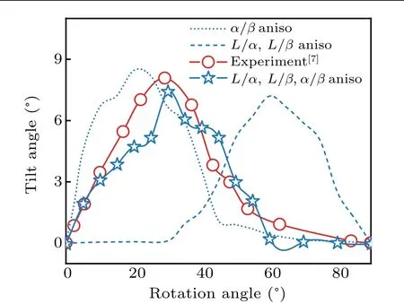
Fig. 7. Comparison between simulated and measured curves of tilt angle(θt)versus rotation angle(θR)for different interface energy anisotropies.
As is well known, the distributions of solute concentration near the front of solid–liquid interface greatly influence the microstructural evolution during solidification. To further explore the effect of anisotropic interface energy on the formation of tilted eutectic, the solute concentration distribution at the front of the solid–liquid interfaces are investigated. Studies[7,25]have shown that the concurrent or competitive contributions of the anisotropies of solid–liquid interface energy and solid–solid one on the formation of eutectic patterns may exist. This implies that the local force balance at triple point is highly complex when interface energy is anisotropic. However, the force balance at the triple point must be maintained during the eutectic solidification,i.e.the following equations need to be satisfied:
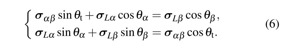
When interface energy is isotropic (|σLα|=|σLβ|), the pinning angle ofα(θα)equals that ofβ(θβ)at triple points.According to Eq.(6),it can be obtained easily thatθtequals 0°,indicating that the component forcesσLαandσLβin thexdirection can be canceled out.And non-tilted growth of lamellae is observed. However, when interface energy is anisotropic,the pinning angleθα/=θβat triple point, indicating thatθtmust not be equal to 0°, and the component forcesσLαandσLβin thexdirection are not canceled out. Thus, there must be a force in thex-axis direction that drives the evolution of eutectic patterns, resulting in the tilted growth of lamellae.When eutectic patterns grow obliquely, the growth rate can be expressed asv=vn/cosθt, and the interlamellar spacingλ=λt/sinθt, wherevnis the normal growth rate of lamellae,andλtis the tangential interlamellar spacing as shown in Fig.1(b). Therefore,if the interface energy is anisotropic,the solution of the solute diffusion equation at the front of the interface is as follows:
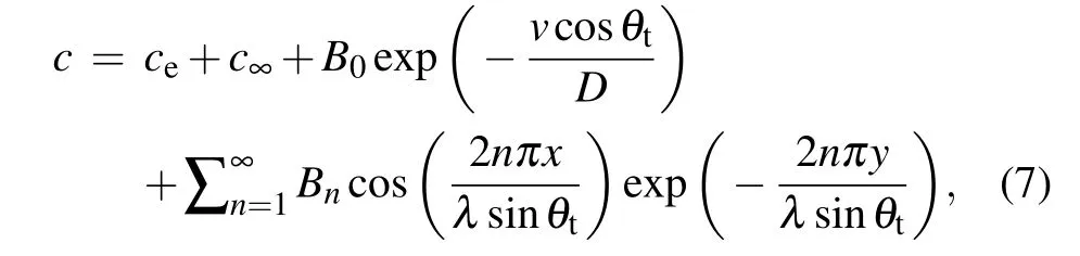

wherec∞is the actual composition far from the solid–liquid interface during eutectic solidification andλiis the half-width of theiphase.According to Eq.(7),the solute distributions at the front of the solid–liquid interface for the tilted(anisotropic interface energy)and non-tilted growth of lamellae(isotropic interface energy)are shown in Fig.8(a). It can be observed that the concentration gradients at the front of the interface with interfacial energy anisotropy are higher than without interfacial energy anisotropy. This indicates that the concentration disturbance near the solid–liquid interface with anisotropic interface energy is larger than without anisotropic interface energy. It should also be noted that no solution can be obtained from Eq. (7) if the tilt angle of lamellar is 0°and interface energy is anisotropic. However,in this case,the solution still exists, which is because only very small variation of pinning angle at triple point occurs to keep the force balance. The small variation will further induce different solute-diffusion rates on both sides of triple point,leading to a large concentration disturbance near the solid–liquid interface. Although this concentration disturbance is not enough to induce the tilted growth of eutectics,it can result in a larger concentration gradient at the front of the solid–liquid interface than the counterpart of isotropic interface energy. Thus, the same conclusion still holds true even when the tilt angle of lamellar is 0°and interface energy is anisotropic. Figures 8(b) and 8(c) show the solute concentration distributions near the solid–liquid interfaces obtained by phase-field simulations with and without anisotropic interface energy,respectively. The differences between the maximum solute concentrations ofα(cminα)at the front of the solid–liquid interface and the equilibrium concentrations in the liquid (ceqL) with and without anisotropic interface energy are shown in the lower right of Fig. 8. The differences between the minimum solute concentrations ofβ(cminβ)at the front of the solid–liquid interface andceqLwith and without anisotropic interface energy are also shown in the lower right of Fig.8. It can be clearly seen that the concentration gradient from phase-field simulation near the solid–liquid interface with isotropic interface energy is lower than with anisotropic one. This result is in good agreement with the theoretical solution of the solute diffusion equation, demonstrating the reliability of our phase field results. Moreover,when the interface energy is isotropic, the solute concentration distribution at the front of the solid–liquid interface is almost symmetrical along theyaxis. However, when the interface energy is anisotropic, it is almost symmetrical along the inclined growth axis. This symmetrical concentration distribution along the inclined growth axis is because different pinning angles at triple point will result in different solute diffusion rates on both sides of triple point. In addition, owing to theGandVexisting along theydirection,the symmetrical axis of solute concentration distribution near the solid–liquid interface that tends to be parallel to the direction ofGmay be observed as shown at point A of Fig. 8(c). Theoretically,this solute distribution near point A of Fig.8(c)cannot maintain stable tilted growth of lamellae. However,if the strength of interface energy anisotropy is sufficiently high, the effect ofGon solute concentration distribution is lower than that of anisotropic interface energy. The effect of concentration distribution near point A of Fig. 8(c) on the tilted growth of the lamellae can be ignored. Consequently, the stable tilted growth of lamellae can be obtained.

Fig. 8. Concentration distributions near the interfaces: (a) theoretical prediction results with isotropic and anisotropic interface energies,respectively,(b)phase-field simulation results with isotropic interface energy,and(c)phase-field simulation results with L/α,L/β,and α/β interface energy anisotropies.
It should also be noted that beside the interface energy anisotropy,the initial conditions,such as initial lamellar spacing,is also an important factor on the tilted growth of eutectics.In this study,however,we restrict ourselves to a range of regular lamellar eutectic formed by the initial lamellar spacing to investigate the effect of interfacial energy anisotropy on tilted growth of eutectic. As to the case of irregular eutectic structures,i.e.,the initial lamellar spacing is beyond this range,so,further studies are needed.interface energy, which is in good agreement with the theoretical analysis of the solute diffusion equation. Our findings not only elucidate the formation mechanism of tilted eutectics but also provide theoretical guidance for controlling the microstructure evolution.
4. Conclusions
Based on the multi-phase field model,the effect of solid–liquid or solid–solid energy anisotropy on the tilted growth of lamellae during eutectic solidification is investigated. And the mutual interactions between solid–liquid and solid–solid interface energy anisotropies are explored. The results show that both the solid–liquid and solid–solid interface energy anisotropies can induce the tilted growth of lamellae. When the anisotropy of solid–solid interface energy and solid–liquid interface energy are considered,the phase-field simulation results are in good agreement with the experimental results,indicating that the anisotropies of solid–solid and solid–liquid interface energies play important roles in tilted growth of eutectic. However,whenθRis small(less than 30°)or large(higher than 60°),the tilted growth of eutectic patterns is mainly controlled by the solid–solid interface energy anisotropy;whereas ifθRis between 30°and 60°, and the tilted growth is jointly affected by both solid–liquid interface energy anisotropy and solid–solid interface energy anisotropy. In addition, the results also demonstrate that the solute concentration gradient with anisotropic interface energy is higher than with isotropic
Acknowledgements
The authors thank the High-Performance Computing Center of Northwestern Polytechnical University, China, for the computer time and facilities.
Project supported by the National Natural Science Foundation of China(Grant Nos.51871183 and 51571165).
猜你喜欢
杂志排行

Chinese Physics B的其它文章
- Formation of high-density cold molecules via electromagnetic trap
- Dynamics of molecular alignment steered by a few-cycle terahertz laser pulse
- Terahertz spectroscopy and lattice vibrational analysis of pararealgar and orpiment
- Molecule opacity study on low-lying states of CS
- Finite-time Mittag–Leffler synchronization of fractional-order complex-valued memristive neural networks with time delay
- Ultrafast Coulomb explosion imaging of molecules and molecular clusters