Plasma propagation in single-particle packed dielectric barrier discharges: joint effects of particle shape and discharge gap
2022-07-13MinZHU朱珉ShengyuHU胡生宇YinghaoZHANG张英豪ShuqunWU吴淑群andChaohaiZHANG张潮海
Min ZHU (朱珉),Shengyu HU (胡生宇),Yinghao ZHANG (张英豪),Shuqun WU (吴淑群) and Chaohai ZHANG (张潮海)
Department of Electrical Engineering,Nanjing University of Aeronautics and Astronautics,Nanjing 211106,People’s Republic of China
Abstract In this work,a single Al2O3 particle packed dielectric barrier discharge (DBD) reactor with adjustable discharge gap is built,and the influences of the particle shape (ball and column) and the residual gap between the top electrode and particle on the electrical and optical characteristics of plasma are studied.Our research confirms that streamer discharge and surface discharge are the two main discharge patterns in the single-particle packed DBD reactor.The strong electric field distortion at the top of the ball or column caused by the dielectric polarization effect is an important reason for the formation of streamer discharge.The length of streamer discharge is proportional to the size of the residual gap,but the number of discharge times of a single voltage cycle shows an opposite trend.Compared to the column,a smooth spherical surface is more conducive to the formation of large and uniform surface discharges.The surface discharge area and the discharge intensity reach a maximum when the gap is equal to the diameter of the ball.All in all,the results of this study will provide important theoretical support for the establishment of the synergistic characteristics of discharge and catalysis in plasma catalysis.
Keywords:low-temperature plasma,packed-bed dielectric barrier discharge,streamer discharge,surface discharge,plasma catalysis
1.Introduction
Plasma reactors are widely used in the industrial production of environmental,energy and chemical synthesis [1,2].Compared with plasma reactors such as microwave discharge,glow discharge,gliding arc discharge,radio frequency discharge and spark discharge,etc,the dielectric barrier discharge (DBD) reactor has received extensive attention because of its simple structure,easy operation,convenient catalyst packing and easy industrial scale-up.However,the low energy efficiency of the plasma reaction of the DBD reactor limits its application and development [3,4].
The introduction of a catalyst is an effective strategy to solve the low plasma reaction efficiency of DBD [5,6].The heterogeneous contact between the solid catalyst and the plasma in catalyst-packed DBD reactors is similar to the gassolid mass transfer process that occurs in a traditional packed bed.Therefore,in the field of plasma catalysis,they are usually called packed-bed dielectric barrier discharges (PBDBD) by researchers.In PB-DBD,the presence of a catalyst stimulates the plasma catalytic reaction and changes the gas discharge environment.Under the synergistic effect of a catalytic reaction and gas discharge enhancement,the efficiency of the plasma catalytic reaction is significantly improved [7-11].
It should also be mentioned that the gas discharge characteristics in PB-DBD are very complicated.In DBD,the main gas discharge patterns are filamentary streamer discharge and surface discharge.But in PB-DBD,besides the above-mentioned patterns,the micro-discharge on the surface of the solid catalyst and the catalyst gap,as well as the discharge on the catalyst surface,also need to be considered[12,13].In addition to common control conditions,such as the DBD structure,applied voltage parameters,etc,the physical and chemical properties of the catalyst,including its dielectric constant [14,15],macroscopic shape [16],microscopic morphology[17,18]and spatial structure[19,20],are all important factors that directly affect the change of gas discharge pattern and plasma catalytic reaction.At present,simplifying the PB-DBD discharge environment and constructing the gas discharge process under specific conditions are the main methods for in-depth study of the PB-DBD gas discharge mechanism.
The single-particle-packed DBD reactor (SPR) establishes the simplest particle surface discharge environment,which helps to reveal the influences of the particle physical characteristics on the gas discharge process.Butterworth et al[21]studied the influence of the dielectric constant(ε)on the plasma propagation dynamics by collecting SPR discharge videos and diagnosing key discharge parameters.Wang et al[14,22]simulated the particle surface discharge in SPR using a two-dimensional(2D)fluid model and studied the dynamics of plasma propagation.Li et al[23,24]studied the evolution of discharge on the surface of cylindrical polytetrafluoroethylene (ε≈2.5) and zirconia (ε≈25) with the help of an ICCD camera and space-time-resolved spectroscopy.Chen et al [25] studied the influence of the size of the discharge gap on the gas discharge pattern around the γ-Al2O3(ε≈9) particles.In short,the conclusions of the above research in SPR are as follows.When the gap between the particle and the electrode is 0,the discharge pattern around the particle is mainly point-to-point discharge at the junction of the particle and the electrode plate and the surface discharge.When the distance between the particle and the electrode is greater than 0,streamer discharge is formed in the gap.High dielectric constant particles can effectively increase the intensity of point-to-point discharge and streamer discharge.However,the space charge is easily trapped on the surface of the high dielectric particles,which limits the propagation of the plasma on the surface of the particles.
In fact,the nature of particle surface discharge is surface ionization waves(SIWs)[26].Compared with other discharge patterns in PB-DBD,surface discharge and streamer discharge have the highest discharge capacity,and are most conducive to the formation of plasma active materials[22,27,28].Wang et al [14] designed a 2D PB-DBD fluid model with a unique structure,and explored the influence of the particle dielectric constant on surface discharges and the positive streamer discharges of dry air.Kruszelnicki et al[27]studied the surface plasma propagation on the ordered rodshaped quartz(ε≈4)by means of time-resolved images and particle models.They found that SIWs and the positive streamer discharge between the quartz and the electrode are the main reasons for the generation of plasma active materials,and these discharges do not exist in isolation,but are closely related.When the streamer propagates to the particle surface,the streamer head voltage is transferred to the plasma sheath and the solid surface,and the plasma sheath electric field can reach 400-800 kV cm−1,which greatly promotes the formation and propagation of surface discharges [29-31].However,few studies have been carried out in this regard,and the synergistic relationship and incentive mechanism of streamer discharges and surface discharges are not clear.
The particle shape and the gap between the particle and the upper electrode are the key parameters of PB-DBD,which jointly influence the electric field distortion,the propagation path of surface discharges,and the geometrical structure and intensity of the streamer discharges [4,32-34].Therefore,in this work,the gap between the particle and the upper electrode is named the residual gap and is defined as Dres,and a SPR experimental device with adjustable Dresis designed.The two common packing materials in PB-DBD,i.e.the Al2O3ball and column,are used.Different streamer discharges and surface discharges are generated by changing Dresas well as the particle shape.The formation and propagation characteristics of streamer discharge and surface discharges are studied by means of optical and electrical parameter diagnostics.The purpose of this study is to try to reveal the relationship between streamer discharges and surface discharges,to elucidate the formation mechanism of large-area uniform discharge on the catalyst surface,and to provide important theoretical support for the establishment of the synergistic characteristics of discharge and catalysis in plasma catalysis.
2.Experiment
A schematic diagram of the SPR experimental device is shown in figure 1.The experimental device mainly includes a lifting platform,a plate-shaped high-voltage electrode,a plate-shaped ground electrode and a barrier dielectric plate.The electrode material is 304 stainless steel,the dielectric barrier plate material is quartz glass,and the thickness is 2 mm.The size of the SPR discharge gap is controlled by adjusting the height of the lifting platform,and the discharge gap size is set to 1-2 mm.An Al2O3ball or column is placed in the discharge gap.The diameter of the ball is 1±0.03 mm,the height of the column is 1±0.03 mm,and the diameter of the column end face is 1±0.03 mm.Then,Dresvaries from 0-1 mm.Air is used as the discharge medium,and its humidity is maintained at 50%-60%.The temperature is maintained at about 20 °C.
The experimental device is driven by an AC high-voltage power supply(Suman CTP-2000P)with an output voltage of 0-30 kV and a frequency of 2 kHz.The high-voltage electrode is located on the top of the SPR and is connected to the high-voltage power supply.The ground electrode is located at the bottom of the SPR and is connected to an external capacitor CM(47 pF).The voltage and current signals are measured with high-voltage probes (Tektronix P6015A) and high-frequency current probes (Zhiyong as CP8030H).The voltage (Ue) on the external capacitor is measured to obtain the charge Q generated in the discharge.The discharge power P is obtained by the area calculation of the Q-VaLissajous.Vais the voltage difference between the high-voltage electrode and the ground electrode on the actual discharge device.The discharge images are recorded by a digital camera (Canon,D350) and a matching macro lens (LAOWA,25 mm,F2.8,2.5-5.0X) with an aperture of F2.8 and an exposure time of 1 s.
3.Results and discussion
3.1.Typical discharge characteristics
Discharge images are the most intuitive way to observe the discharge characteristics.Discharge images around the Al2O3ball under different values of Vaare shown in figure 2,while Dresis maintained at 0.5 mm,and the positions of the ball pole and the equator are marked out in the actual ball picture.It can be seen that there are at least three different discharge patterns around the ball.Firstly,a stable and slender streamer discharge channel is formed between the ball and the highvoltage electrode,which is attributed to the electric field distortion caused by the dielectric polarization effect.Secondly,surface discharges form,with the streamer reaching the upper pole of the ball.This is because the electric field strength of the streamer head is rapidly amplified at the interface of the streamer and the solid,resulting in the formation of surface discharges [35].Thirdly,with the applied voltage increased,the surface discharge is split into two different discharge patterns.When the voltage is 15 kV,it is obvious from figure 2 that the plasma begins to leave the surface of the ball and multiple discrete stream discharges are formed between the surface of the ball and the barrier dielectric plate.It is noteworthy that the surface discharge will continue to spread and form a lot of complete surface discharge channels along the spherical direction with the voltage increasing to 18 kV.Of course,at this voltage,all the discharges become brighter,and a large number of surface discharges are also formed at the interface between the discrete discharge channels and the dielectric plate.
Figure 3 shows discharge images around the Al2O3column under different applied voltages,while Dresis 0.5 mm.The position of the end face,the vertex and the vertex connection line are given in the Al2O3column image.We can find many unique discharge characteristics around the column from the discharge pictures,which are completely different from the sphere.The first is the number of discharge channels at the top of the column.When Vais low,with a value of about 14 to 16 kV,two streamer discharge channels are formed between the vertices and the high-voltage electrode.As the applied voltage increases,the geometric characteristics of the main streamer discharge change dramatically,and the streamer discharges completely fill in a rectangular region surrounded by the vertex line and the high-voltage electrode.The second significant difference is the location of the surface discharges.Surface discharges are more likely to form at vertices and the edges rather than its face,including the side face and end side.
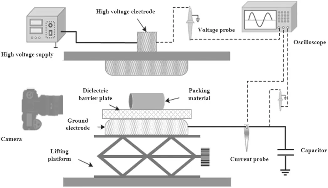
Figure 1.Schematic diagram of the SPR experimental device.

Figure 2.Discharge images around the Al2O3 ball when Dres is 0.5 mm.

Figure 3.Discharge images around the Al2O3 column when Dres is 0.5 mm.
In addition,we also observe that the discrete discharge formed between the column surface and the dielectric plate has a unique correspondence with the shape of the packing material.Xiong et al [33] also found similar laws when studying the propagation characteristics of gas discharges on dielectric surfaces with different shapes through numerical simulation.To confirm that,from the evolution of the surface discharge image of the ball,the discrete discharge is the continuation of the surface discharge.It is formed on the surface of the dielectric and propagates to the dielectric plate along the surface normal.Due to the influence of the‘tip effect’ on the dielectric surface,surface discharge is more likely to be generated at irregular geometrical shapes of the dielectric surface,such as the sides and vertices of a cylinder,which directly determine the formation and propagation direction of subsequent discrete discharges.
In this study,a residual gap of 0.5 mm is set as a typical working condition.Under this gap,the streamer discharge channel could be stably formed on the top of the packer,which helps to explore the relationship between the streamer discharge and the other discharges.It can be seen from the above discharge images that streamer discharge is the most important discharge pattern around the ball or column.The current signal of the streamer discharge appears in the form of multiple current pulses under an AC voltage source [19,36].Figure 4 shows the current characteristics of a single Al2O3ball packed under different Vaand the same Dres(0.5 mm).When the ball is used as the PB-DBD packing material,the phase of the current pulse is relatively fixed,mainly appearing at the voltage falling edge and its zero-crossing point,as well as the voltage rising edge.The current pulse,no matter the amplitude or the number of times,changes almost linearly with Va.
Figure 5 shows the current characteristics for the Al2O3column under different Vaand the same Dres,i.e.0.5 mm.The evolution of current pulses with the Al2O3column,especially the amplitude,does not change linearly with Va.At the initial stage of discharge,that is,Vais less than 14 kV,the surface discharge of the column is stronger and the number of discharges is more than that of the ball.However,the current amplitude shows a downward trend as Vaincreases to 15-16 kV.It can be found from the discharge image that the number of discharge channels and the area covered by the top streamer show an upward trend with the applied voltage.This feature can be attributed to the fact that the formation of multiple streamers in a limited space is not conducive to the accumulation of the surface energy of the dielectric,resulting in the reduction of the discharge energy of a single streamer[37].Increasing the voltage amplitude provides a guarantee for the gas discharge energy input.As the voltage exceeds 17 kV,large current pulses continue to appear on the surface of the column,and the amplitude and the number of discharges are higher than those of the ball.
3.2.Evolution of discharge characteristics under different residual gaps
The residual gap is another important structural parameter involved in this study,which directly affects the formation and propagation of discharge.From the variation of the discharge image near the ball under different residual gaps,as shown in figure 6,it can be seen that,as Dresdecreases from 0.5 to 0.1 mm,the main streamer discharge channel gradually changes from a concentrated single channel to a divergent multi-discharge channel.As a result,as the gap continues to decrease,the contact area between the streamer discharge and the sphere continues to increase,and the intersection point between the discrete discharge channels and the sphere continues to extend to the equator.When Dresis equal to 0,the surface discharge becomes the main gas discharge pattern,and the streamer discharge and discrete discharge completely disappear.
Figure 7(a) shows the discharge image around the side face of the Al2O3column while Dresis 1 mm,0.5 mm,0.1 mm and 0 mm and,Vais 18 kV.It should be pointed out that the discharge characteristics of the streamer at the top of the cylinder are very complicated and largely depend on the size of the residual gap.When Dresis set to 1 mm,two obvious streamer discharge channels appear at the apexes of the column.As the gap is reduced to 0.5 mm,multiple discharge currents are formed on the top.However,when Dresis 0.1 mm,only two tiny streamer discharge channels are observed at the apexes.When Dresis 0 mm,no obvious discharge process is observed on the side,and the main discharge is concentrated on the end surface.Figure 7(b) shows the discharge image around the end face of the Al2O3cylinder while Dresis 1 mm,0.5 mm,0.1 mm and 0 mm,and Vais 18 kV.It can be found that with the decrease of the residual gap,the end surface discharge channels gradually gather from a discrete discharge process to a bright,concentrated and complete discharge channel that develops along the center line of the end surface.

Figure 4.Current characteristics for Al2O3 ball at different Va when Dres is 0.5 mm.

Figure 5.Current characteristics for Al2O3 column at different Va when Dres is 0.5 mm.

Figure 6.Discharge images around Al2O3 ball at different Dres while Va is 18 kV.
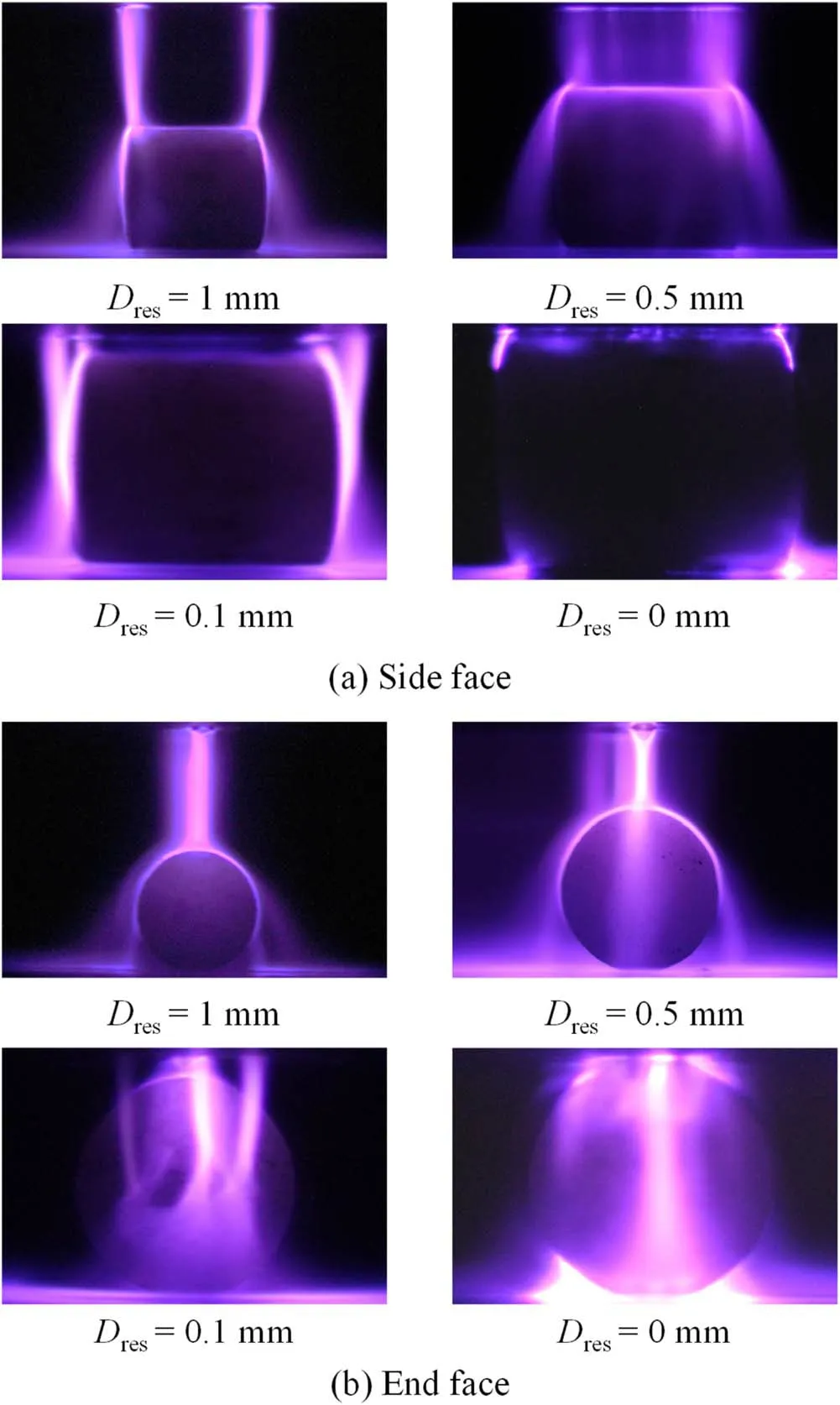
Figure 7.Discharge images around Al2O3 column at different residual gap lengths.

Figure 8.Influence of Dres on the current pulse distribution in one voltage cycle while Va is 18 kV.
From the evolution of the surface discharge images with the gap,the following important conclusions can be found.Reducing the residual gap helps to form a larger area on the surface of the ball and develop a more adequate surface discharge process.In plasma catalysis,the formation of a largearea and uniform plasma on the catalytic surface is an expected result of researchers [20,38].In theory,this will fully increase the mass transfer rate of plasma active substances and catalytic active components,and affect the plasma catalytic reaction efficiency.However,for the cylindrical surface discharge,due to its irregular geometry,the extensive formation of surface discharge limits the future application of cylindrical catalysts in the field of plasma catalysis.
The influence of the size of Dreson the current pulse distribution in one voltage cycle is shown in figure 8.As seen in figures 8(a) and (c),the high current pulses mainly occurred for the Al2O3ball under gaps of 0 mm,0.1 mm and 1 mm,and the number of discharges in a single voltage cycle decreased with the increase in gap length.However,the current change law was complicated for the column.Increasing Dresis helpful to form large current pulses when the gap size is greater than 0.3 mm.But for the small gaps of 0.1 mm and 0 mm,it is difficult to find a qualitative law only from the evolution of current amplitude.In addition,the trend of the number of discharges with the voltage in a single voltage cycle around the column is the opposite of the number of discharges of the ball.
When the ball is used as the packing material of PBDBD,the influence law of Dreson the current pulse amplitude and discharge frequency is clear and definite.The electric field is an important parameter that affects the gas discharge.When the applied voltage is the same,the strong electric field formed by the small residual gap is the main reason for the increase in current pulse and amplitude.Besides that,the main reason for the formation of large gaps and large current pulses can be attributed to the strong distorted electric field formed by the head of the streamer.According to the electromagnetic field theory,under the condition of certain structural parameters,the size of the external electric field somewhere in space is only related to the value of the applied voltage.However,according to the streamer discharge theory,the streamer discharge head electric field strength(Estreamer)is equal to the external electric field (Ea) plus the space charge electric field at the streamer channel head (Ehead).According to the gas discharge theory [39],the streamer is the result of the excessive development of the electron avalanche.The distorted strong electric field generated by the head of the streamer caused by the electron avalanche accelerates the development of the ionization,continuously triggers spatial photoionization and secondary electron avalanche,and pushes the streamer forward.Therefore,as the length of the streamer channel increases,the space charges at the head of the streamer continue to be accumulated,and the discharge current amplitude increases accordingly.However,the disadvantage is that it is relatively difficult to form a streamer discharge in a long discharge gap,and the voltage required for plasma ignition will also increase significantly.
The evolution of the current on the surface of the column is completely consistent with the trend of the gas discharge pattern with the residual gap.It can be seen from figure 7 that the discharge pattern on the column surface changes dramatically under different residual gaps.When Dresis 0.5 mm,a large number of long streamer discharge channels are formed on the top of the column,which promotes the increase in the number of discharges.However,in other cases,only 2-3 streamer discharge channels or some tiny filamentary discharge channels are formed on the top of the column,which leads to a decrease in the number of discharges.
The plasma ignition voltage (VP-I) is defined as the minimum voltage of a visible discharge plasma in the discharge gap.Figure 9 shows the relationship between VP-Iand the residual gap.VP-Ishows a gradual decreasing trend as Dresdecreases from 1 mm to 0.1 mm.However,as Dresis reduced to 0 mm,that is to say,the electrode is very close to the packing material,the value of VP-Iincreases significantly.It can be seen in figure 9 that the corresponding VP-Iof the ball and cylinder are 8 kV and 10 kV,respectively,since Dresis 0.1 mm.But VP-Ifor the ball and cylinder increased to 14 kV and 13 kV,respectively,as Dresdecreased to 0 mm.The first phenomenon is easy to explain.In PB-DBD,the distortion electric field at the top of the packing material is continuously enhanced with the decrease of Dres,which promotes the formation of streamer discharge.When the remaining gap between the electrode and the packing material is reduced to 0,a discharge ‘dark zone’ is formed,which causes the early gas discharge to be unobservable to the naked eye [25],thereby affecting the accuracy of the value of VP-I.

Figure 9.Effect of the size of the residual gap on the plasma ignition voltage.

Figure 10.Effect of particle shape and size of residual gap on discharge power.

Figure 11.Schematic diagram of the SPR 3D model.

Figure 12.Electric field distribution on the surface of the ball and the column while the residual gap is 0.5 mm.
In addition,VP-Idiffers with the different shapes of the packing material.When Dresis 1 and 0.5 mm,the plasma is more likely to be ignited at the top of the Al2O3cylinder.However,as Dresis reduced to 0.3 and 0.1 mm,the VP-Irequired for the top of the Al2O3ball is lower.
Furthermore,the discharge power under different gaps is shown in figure 10,while the applied voltage is 18 kV.The geometric structure of the packer is different,and the evolution of the discharge power with the gap is also different.The gas discharge patterns and characteristic parameters(streamer channel length,single voltage cycle discharge times,etc)clearly affect the discharge power.For the ball,the maximum discharge power appears at the gap of 0 mm.Compared with the discharge power with a residual gap of 0.1 mm,the average discharge power of ten discharge cycles is increased by 95.6%.However,when the residual gap is reduced from 0.3 mm to 0 mm,the value only increases by 77.1%.The reason for the rapid increase in power can be partly attributed to the transition of the discharge pattern.When the residual gap is reduced from 0.1 mm to 0 mm,the main discharge pattern on the ball surface changes from streamer discharge to surface discharge.Comparing the discharge power of the gas on the surface of the ball since the residual gap is 0.1-1 mm,it can be found that the formation of a long streamer discharge contributes to the improvement of the discharge power.For example,as the residual gap increases from 0.1 mm to 1 mm,the discharge power on the surface of the ball increases by 22.5%.Compared with the ball,the effect of the residual gap on the discharge power of the column surface is not significant.The maximum discharge power of the column surface is formed when the residual gap is 0.1 mm,and its value is 14.39% higher than the result of 0 mm.It can be seen from the discharge images in figure 7 that the column surface discharge patterns are basically the same under these two working conditions.With a residual gap of 0.1 mm,the number of discharges on the surface of the column is twice that observed when the gap is 0 mm.The formation of more column surface discharges promoted the increase in power.When the residual gap is set to 0.3 mm or 1 mm,the column surface discharge power was better than 0.5 mm.This may be attributed to the strong streamer discharge formed at 1 mm and more streamer discharge formed at the top of the column at 0.3 mm.
3.3.Simulation calculation of electric field
The electric field intensity is an important electrical parameter for studying gas discharge.In the gas discharge process,the actual electric field of the discharge gap is superimposed by the external electric field caused by the applied voltage and the electric field caused by the plasma and space charges.Before the gas discharge is formed,the space charge field is zero,and the external electric field plays a decisive role in exciting the gas discharge.In PB-DBD,the research object of this work,in addition to the influence of DBD structural parameters and external power excitation,the polarization effect of the gap-filled dielectric under the action of an external electric field will cause serious distortion of its surface electric field,which will change the gas discharge mode and subsequent propagation characteristics.Therefore,in this section,the electric field near the ball and column in the packing gap is simulated and calculated,and the surface discharge characteristics of the ball and column are explained based on the calculation results.
The 3D electrostatic field distribution of the discharge gap is calculated using COMSOL software.Using a geometric model similar to the experimental device,the dielectric constant of Al2O3is set to 9,the dielectric constant of air is set to 1,the dielectric constant of the dielectric barrier SiO2is set to 4.2,and the applied voltage is set to 9 kV(peak value).A schematic diagram of the SPR 3D model is shown in figure 11.In order to describe the characteristics of the electric field distribution on the surface of the ball and the column,the directions of the x,y and z axes are also given.Three different cross-sections were taken to study the influence of the packer and the residual gap on the space electric field.The surface along the x-y plane and passing through pole A of the ball is called section 1.The surface,which passes through the cylinder vertex B,along the y-z plane and the x-y plane,is defined as sections 2 and 3,respectively.The unit of the electric field is V/m.
The surface electric field distribution of the two dielectrics under typical characteristic conditions (residual gap of 0.5 mm) is shown in figure 12,where normE is the electric field mode,and Ex,Eyand Ezare positive in the x,y and z axis directions,respectively.It can be seen that the electric field distribution on the surface of the ball and the column is quite different.As far as the ball is concerned,the electric field strength is the highest along the y-axis,and its highest value appears at the pole of the ball.On the surface of the column,the surface electric field distortion is relatively strong in the three directions of the x and y axes.Due to the tip effect of the cylinder edge,the maximum electric field strength is formed near the end face and the vertex of the cylinder.At the apex of the cylinder,the Excomponent of the electric field rises very rapidly in the x-axis direction.At the junction of the cylindrical end face and the side face,the electric field mode and the electric field Eycomponent change most notably.The strong electric field formed at the apex of the cylinder and the sphere is the main reason why the streamer discharge is formed here first.The strong electric field at the intersection of the cylindrical end face and the side surface may be an important factor that prevents it from forming a wide range of surface discharge.
Figure 13 shows the variation of the electric field(normE)of the three cross-sections with the residual gap.The maximum electric field strength is formed at the apex of the sphere and the cylinder,and is continuously weakened along the y-axis.As the residual gap decreases,the field strength near the apex of the ball and cylinder continues to rise.It is worth noting that when the residual gap is reduced from 0.1 mm to 0 mm,the maximum electric field at the apex of the ball is increased by more than two times.As for the surface electric field of the column,the electric field value at the apex does not increase significantly,and the electric field intensity of section 2 even shows a downward trend.

Figure 13.Electric field distribution (normE) under different residual gaps.

Figure 14.Electric field distribution (normE) under different conditions.
In addition,we also calculated the electric field distribution when the discharge gap is packed with spherical particles.Two different packing conditions are considered.Condition I has three particles of the same size (1 mm in diameter).Condition II has one large particle (1.4 mm in diameter) and two small ones (1 mm in diameter),and the electric field distribution(normE)under these conditions is as shown in figure 14.For condition I,since the three particles are the same size,the electric field distribution around the particles does not change due to the increase in the number of packers.Chen et al[25]also studied the effect of the number of spherical particles packed in the discharge gap on the discharge.The results show that due to the similar size of spherical particles,there is no significant difference in discharge characteristics near each particle after multi-particle packing.However,when packed with spherical particles of different sizes,the electric field distribution on the surface of each particle showed obvious differences.We firmly believe that this will undoubtedly change the gas discharge characteristics.This is mainly due to the fact that in the actual discharge process,the electric field distribution in the discharge gap changes dynamically.The electric field distortion of the residual gap between the large particles and the upper electrode is stronger,which is more likely to lead to the first generation of streamer discharge and break the original electric field distribution.Under this condition,filamentary discharges between small particles and large particles are more likely to occur,rather than streamer discharges formed in the residual gap between small particles and the upper electrode [14].
3.4.Consequences for plasma catalysis of PB-DBD
Our research indicates that the residual gap and the packing materials with different shapes significantly affect the plasma characteristics,which will definitely affect the performance of the packed-bed reactor in the low-temperature plasma catalytic reaction.
For example,we found that the large residual gap makes it easy for long streamer discharges to be formed,which is beneficial to the improvement of the discharge power and the intensity of a single discharge.For the ball,when the discharge gap is the same as the diameter of the ball,the strong electric field formed in the pole region of the ball helps to double the discharge intensity.Numerous studies have shown that the discharge intensity is a key factor affecting the plasma catalytic reaction.Regarding the plasma-catalyzed methane dry reforming or CO2cracking reaction,the reaction efficiency is proportional to the discharge intensity [40-43].Therefore,choosing a reasonable residual gap is very important for the plasma catalytic reaction.
Furthermore,we confirm that the geometry of the packing material and the size of the residual gap together determine the formation and propagation of the surface discharge.In this study,when the ball is used as the packing material and the discharge gap is the same as the diameter of the ball,surface discharges with higher intensity and larger propagation area are formed on the surface of the ball.In the introduction,we mentioned that surface discharge is essentially a surface ionization wave,which has the advantages of high discharge intensity and close contact with the catalytic surface[14,25,26,44].The high-intensity discharge process helps to increase the content of plasma active components.Plasma catalysis is a heterogeneous catalytic reaction.Reducing the contact distance between the plasma active components and the catalytic center is obviously an effective strategy to improve the plasma catalytic reaction.However,this is only a hypothesis based on the heterogeneous catalytic mechanism,and the relationship between the plasma catalytic reaction efficiency and catalytic surface discharge has yet to be confirmed.The value of the work in this paper is to obtain the conditions for the formation of a strong discharge on the catalytic surface,which provides a theoretical guarantee for the research in this area.
4.Conclusions
In this work,the influence of the shape of the packing material and the residual gap on the gas discharge characteristics in the SPR experimental device was studied by means of electrical diagnosis and optical imaging.
Our studies predict that the plasma formation in an SPR in air may exhibit four patterns of discharge behavior,i.e.streamer discharge,surface discharge,discrete discharge and filamentary micro-discharge.
The polarization effect of the dielectric causes the electric field distortion at the top of the packing material to be the main cause of streamer discharge.The number and intensity of streamer discharge are determined by the shape of the packing and the length of the residual gap.When the gap is large,1-2 clear streamer discharge channels are formed on the top of the ball or column.With the decrease in the residual gap,the number of streamer discharge channels gradually increases,but the intensity of single streamer discharge shows a weakening trend.When the residual gap is similar to the geometry of the packing material,the streamer discharge completely disappears,and a large number of filamentary micro-discharges are formed at the tiny gap between the packing material and the electrode.
In addition to the external discharge parameters,the surface discharge intensity and propagation path are related to the residual gap and the shape of the packing material.It is difficult to form a large-scale surface discharge on the surface of the column.The tip effect of the dielectric leads to strong electric field distortion on the side of the column,which severely inhibits the formation of surface discharge on its side and end faces.On the contrary,the electric field distribution on the ball is uniform,and the area of the surface discharge continues to increase with the decrease of the residual gap.When the residual gap is 0 mm,the size of the discharge gap is equal to the diameter of the ball,and the surface discharge area and the discharge intensity reach the maximum.
In plasma catalysis,the discharge pattern and its intensity on the catalyst surface are important factors that determine the concentration and spatial distribution of plasma active substances.Therefore,this research is of great significance to better understand the characteristics of the surface discharge of catalysts and to establish the relationship between surface discharge and catalytic reactions.
Acknowledgments
The work was supported by the National Key R&D Program of China (No.2021YFF0603100),the Natural Science Foundation of Jiangsu Province (No.BK20200452),the Postdoctoral Research Foundation of China (No.2020M681584) and National Natural Science Foundation of China (No.51977110).
猜你喜欢
杂志排行

Plasma Science and Technology的其它文章
- Recent progress on the J-TEXT three-wave polarimeter-interferometer
- Design of the stripping unit and the electromagnetic analysis unit for the E//B NPA on HL-2A/2M tokamak
- Space-resolved vacuum-ultraviolet spectroscopy for measuring impurity emission from divertor region of EAST tokamak
- Development of a combined interferometer using millimeter wave solid state source and a far infrared laser on ENN’s XuanLong-50(EXL-50)
- Bench test of interferometer measurement for the Keda Reconnection eXperiment device (KRX)
- Neutron yield measurement system of HL-2A tokamak