Investigation of the confinement of high energy non-neutral proton beam in a bent magnetic mirror
2022-04-15FangpingWANG王芳平HengZHANG张恒ShengZHANG张晟andWenshanDUAN段文山
Fangping WANG(王芳平),Heng ZHANG(张恒),Sheng ZHANG(张晟) and Wenshan DUAN (段文山),
1 College of Physics and Electronic Engineering,Northwest Normal University,Lanzhou 730070,People's Republic of China
2 Advanced Energy Science and Technology Guangdong Laboratory, Huizhou 516003, People's Republic of China
Abstract By using the particle-in-cell (PIC) simulation method, we studied how the proton beam is confined in a bent magnetic mirror.It is found that the loss rate of the charged particles in a bent mirror is less than that in the axi-symmetric mirror.For a special bent mirror with the deflection angle of the coils α=45°, it is found that the loss rate reaches maximum value at certain ion number density where the ion electrostatic oscillation frequency is equal to the ion cyclotron frequency.In addition,the loss rate is irrelevant to the direction of the proton beam.Our results may be helpful to devise a mirror.In order to obtain the least loss rate, we may choose an appropriate deflection angle, and have to avoid a certain ion number density at which the ion electrostatic oscillation frequency is equal to the ion cyclotron frequency.
Keywords: bent magnetic mirror, proton beam, particle-in-cell method
1.Introduction
A wide variety of plasmas, such as high-ion-energy quasineutral plasma, plasmas with high-energy electrons, nonneutral plasmas,electron-positron plasmas,plasma discharges have been studied in a magnetic mirror field [1–10].Most of the early studies on the neutrality plasma in magnetic mirrors focused on axi-symmetric magnetic mirrors [1–5], for example, plasma discharges with a high temperature of bulk electrons in the axially symmetric magnetic mirror [3], low energy electron-positron plasmas[4,5]confined in a compact magnetic mirror.Moreover,there are also some works on the non-neutral plasmas, such as non-neutral electron plasmas[6, 7], electron beam [8, 9]and proton beam [11], studied by experiments and numerical simulation in a magnetic mirror.The magnetic field at the corona ring is usually studied by using the non axi-symmetric magnetic mirror field[12–16].Furthermore,most of the studies on the coronal mass ejections and related phenomena in the laboratory are also investigated by using the non axi-symmetric magnetic mirror field.
Recently, the superconducting proton linac [17, 18] has achieved continuous-wave proton beam whose power is greater than 120 kW for 108 h [19].The test experiment demonstrated a continuous-wave proton beam whose energy is about 20.18 MeV and the current intensity is about 10 mA.Moreover, using magnetic field to guide and focus ion beam[20–24] has become an important part in the development of ion beam application technology, which lets the ion beam move in magnetic field.
However,there are few works on the non-neutral plasmas in a bent mirror.Following the procedure of the study of the non-neutral plasma in axi-symmetric magnetic field [9, 10],we study the confinement of non-neutral proton beams in a bent magnetic mirror in the present work.It is found that the loss rate of the ions in a bent magnetic mirror is much smaller than that of the axi-symmetry mirror.Based on this conclusion, we can try to design a bent magnetic mirror to confine charged beam which has potential applications in many branches such as the fusion, fission, etc.
The paper is organized as follows.In section 2,the mirror geometry and simulation parameters are described.In section 3, we present the simulation results with different magnetic configurations and different initial conditions of proton beam.In section 4,we study how the proton beam and charged particles move in the bent mirror.Finally, our conclusions are given in section 5.
2.Mirror geometry and magnetic field
We consider a classic two-coil magnetic mirror, as shown in figure 1,where we set up Cartesian coordinate system,x axis is in the direction from one center to the other of the coils,and the origin is at the midpoint of two centers.Then the centers of two coils are at the points ofrespectively.The bent mirror studied in the present work is obtained by rotating the right coil clockwise with an angle α with respect to the axial ofand the left coil anticlockwise with an angle α with respect to the axial of, where L is the distance between two centers.The magnetic field produced by this bent mirror can be given by the Biot–Savart law.
The magnetic field map of axi-symmetric magnetic mirror (α=0) is shown in figure 2, where L=52 cm, the radius of the coil R=8 cm, and the mirror ratio Rm=5.9.Figure 2 also shows the corresponding magnetic field maps of the bent mirrors with α=30°,α=45°,α=60°and α=85°,respectively.The magnetic field lines with α=45°are shown in figure 3.It is observed that the magnetic field of the bend mirrors is not axi-symmetric.
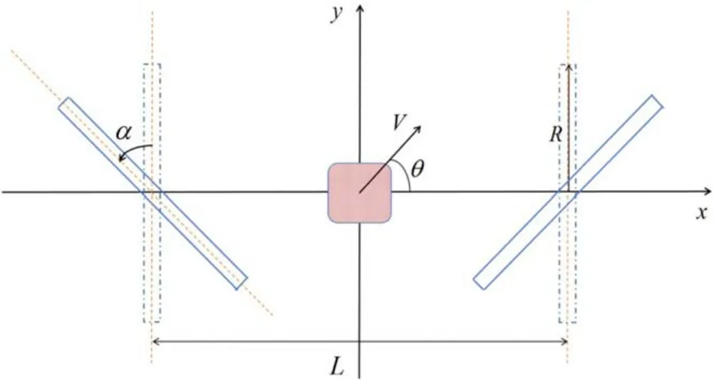
Figure 1.The diagrammatic sketch of the mirror.α is the deflection angle, L is the distance between the center points of the two coils,and R is the coil radius.The shadow area is the region of the initial plasma,V is the beam velocity,and θ is the angle between the beam direction and the horizontal direction.

Figure 2.The colour maps of the magnitude of magnetic field|B|of magnetic mirrors in the region of 0.7 m×0.3 m with L=52 cm,and R=8 cm.For the axi-symmetric mirror (α=0), the mirror ratio is Rm=5.9.For the bent mirrors, the angles are α=30°, α=45°,α=60° and α=85°, respectively.The unit of the magnitude of magnetic field in the colour map is tesla (T).
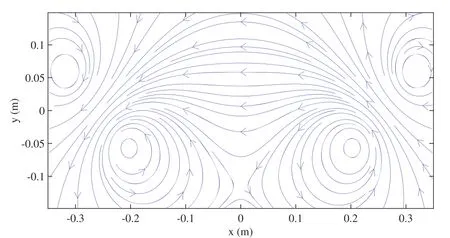
Figure 3.The distribution of magnetic field lines with α=45°.
Suppose that a proton beam is launched into the center of the bent mirror, we now numerically study the dynamic behavior of the proton beam in a bent mirror by using the PIC method.PIC code of the collisionless electromagnetic model is used, in which two-dimensional space (2D) and threedimensional velocity (3V) components (2D-3V) are considered.Under the plasma parameters used in the simulation,the mean free path of ion–ion Coulomb near collision can be calculated bym, where niis the number density, σiiis the cross section,is the Landau length, ε0is the vacuum dielectric constant, kBis the Boltzmann constant, and Tiis the temperature.But in our simulation, the magnetic mirror’s scale is 10-1m.Therefore,the ion–ion collision is negligible.For the high-density plasma,when the mean free path of Coulomb near collision is in the order of the size of plasma,the ion–ion collision should be considered.
The initial conditions are as follows.Proton beam is initially in the region (-1 cm ≤x ≤1 cm, -1 cm ≤y ≤1 cm),the launch speed of the proton beam is V,the direction of the launch speed is θ (the angle between the beam velocity and the positive x direction),the number density of the proton beam is ni0, and its temperature is Ti.
The simulation region is (-0.35 m ≤x ≤0.35 m, -0.15 m ≤y ≤0.15 m),and the weight of super particles(SPs)is set as Q=ni0/100.Based on the limitation of PIC method, the simulation parameters are chosen as follows:the grid number is 200×200,space step dx=3.5 mm <3λDi,dy=1.5 mm <λDi, time step dt=10-12(λDiis the Debye length of ions, ωpiis the ion electrostatic oscillation frequency).Absorbing boundary is used in our simulation for ions and fixed boundary is used for fields (electric field and magnetic field).We choose the absorbing boundary as the simulation boundary at x=±0.35 m and y=±0.15 m, as shown in figure 2.
The equation of motion of SPs is Newton’s equation:

where mp,vp,rpare the mass,velocity and position of the SP,respectively.Fpis the force acting on the SP, which is given as follows

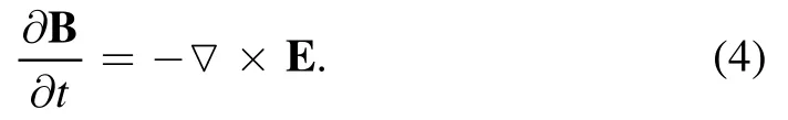
where qpis the charges of the SP,E and B are the electric and magnetic fields evaluated at the particle position,respectively.The fields are computed by solving Maxwell’s equations[25].The magnetic field is calculated from Faraday’s law:
The electric field is calculated from the Maxwell–Ampere law:

where ε0is the vacuum dielectric constant,μ0is permeability of vacuum,and J is the current density.The current densities are calculated in each cell by the following equation:

where Δx and Δy are space step in the x direction and y direction of the cell g respectively, ∑pindicates the sum of all SPs in the mesh g,qpis the charges of each SP,vpis the velocity of the SP in the cell g,is the interpolation function, blis the b-spline functions of order l,rg=(xg, yg) is the coordinate of the center of the cell g and rp=(xp,yp)is the coordinate of the pth SP.The charge densities are computed in each cell by the following equation:

3.The confinement of proton beam in a bent mirror
In this section, we focus on the confinement effect of bent magnetic mirror on proton beam.For this purpose,we define a loss rate, where Nlostis the number of leaked particles from the mirror and N0is the number of initial particles in the mirror.
The dependence of the loss rate of the charged particles on the system parameters for an axial symmetric mirror has been studied previously[9,10].It is reported that the loss rate decreases as the mirror ratio increases [10].Due to this reason, we fixed the mirror ratio Rm=5.9, the radius of the coil R=8 cm, the distance between two centers of coils L=52 cm and the current of coil I=1.0×10⁶A.We mainly focus on the dependence of the loss rate on the deflection angles α of the coils in the present work.
Figure 4(a) shows the loss rate as a function of time for different angles α (α=0 is the axi-symmetry magnetic mirror).The parameters of proton beam are ni0=5.0×10¹⁶m-3, Ti=5 keV, θ=85°, and V=6.9×10⁵m s-1.Notice from figure 4(a) that the loss rate in a magnetic mirror increases as the time increases.Moreover, it seems that the loss rate in a magnetic mirror decreases as the angle α increases.In order to further understand the dependence of the loss rate on the angle α, the variations of the loss rate with respect to α are shown in figure 4(b) at time t=20 μs (blue short dash line in figure 4(a)) and t=25 μs (pink short dash line in figure 4(a)).We have defined the confinement time for a mirror [10].Figure 4(b) also shows the dependence of confinement time on angle α.Both loss rate and confinement time could reflect the confinement effect of a magnetic mirror.The smaller the loss rate (the longer the confinement time),the better the confinement effect.In the next section, we pay attention to the loss rate from figure 4(b).
It can be seen that when α increases, the loss rate of particles decreases.For the axi-symmetric mirror, the loss of particles is mainly caused in the axis direction.Furthermore,the larger the magnetic mirror ratio Rm(Rm=Bm/B0,Bmand B0are the maximum and minimum of the strength of magnetic field on the axis respectively), the less the loss of particles[9,10,26,27].Figure 5(a)shows the dependence of the strength of magnetic field on the spatial coordinate x for y=0 and y=±0.035 m, with α=0 and α=45° respectively.Figure 5(b)is the dependence of the Bm/B0on the α.It is noted that Bm/B0increases as α increases, which may be the main reason why the loss rate decreases as α increases.
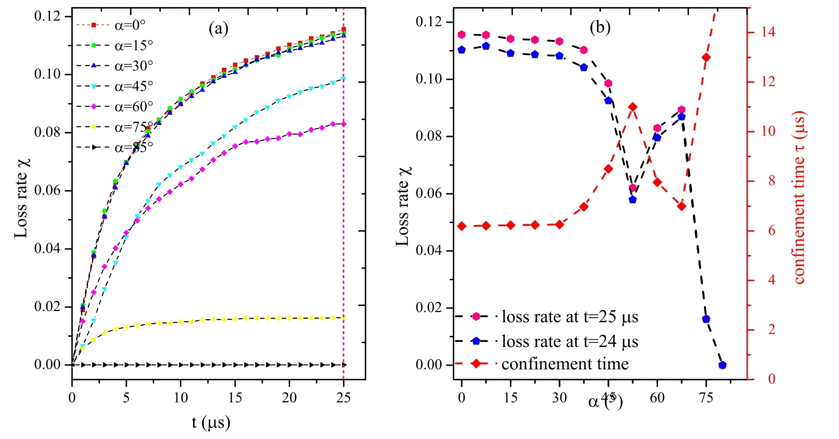
Figure 4.(a)Loss rate of SPs as a function of time for different angles α.(b)Dependence of loss rate on the angle α with time t=20 μs and t=25 μs.Confinement time as a function of angle the angle α (red diamonds).The parameters of the proton beam are number density ni0=5.0×10¹⁵ m-3, temperature Ti=5 keV, beam speed V=6.9×10⁵ m s-1 and launch direction θ=85°, respectively.

Figure 5.(a)The dependence of the strength of magnetic field on the spatial coordinate x for y=0.0 and y=±0.035 m,where the red solid lines correspond to α=0 and blue dotted lines correspond to α=45°.(b) The dependence of the Bm/B0 on α=0–52.5°.

Figure 6.Diagram of SPs distribution and the distribution of magnetic field lines with different angles α.(a) α=30°, (b) α=45°, (c)α=67.5°,(d)α=85°at t=0.15 μs.The parameters of the proton beam are number density ni0=5.0×10¹⁵ m-3,temperature Ti=5 keV,beam speed V=6.9×10⁵ m s-1 and launch direction θ=85°, respectively.

Figure 7.(a) Dependence of loss rate on number density and temperature of proton beam at time t=25 μs, (b) dependence of loss rate on launch direction and beam speed of proton beam at time t=25 μs.In the simulation, the fixed parameters of the proton beam are number density ni0=5.0×10¹⁵ m-3, temperature Ti=5 keV, beam speed V=6.9×10⁵ m s-1 and launch direction θ=85°, respectively.
However, as α continues to increase, the loss rate increases.This is due to the following reason.As α continues to increase, a large number of particles are leaked from the bottom of the mirror,as an example,see in figure 6(c).When the coils are deflected at a large angle, for example, α=45°and 67.5°, a minimum value of the magnetic field appears below the center of the two coils (see in figure 6(b) and figure 6(c))due to the opposite direction of the magnetic field lines at this point.It seems that the larger the deflection angle in a certain region, the closer the minimum region to the center of the magnetic mirror.When the charged particles close to the minimum point of the magnetic field, the magnetic force of the charged particles is so small that they will run out of the calculation boundary due to the thermal motion.Therefore, the loss through the bottom may be the radial diffusion.
When α tends to 90°, the particles almost move around the magnetic field lines.In this case, the loss rate is about zero, see in figure 6(d) where α=85°.
In summary,when the coils deflect at a certain region,the particle loss rate decreases.But when the deflection angle of the coils is large enough, for example, 67.5°, 85°, it is not a magnetic mirror any more.
We now study the dependence of the loss rate on the different parameters of the proton beam in the bent mirror at time t=25 μs, where α=45°, as shown in figure 7.Figure 7(a) shows the dependence of the loss rate on the initial number density of the proton beam,represented by the red pentagon, and on the temperature of the proton beam,represented by a blue five-pointed star.Figure 7(b)shows the dependence of the loss rate on the beam speed by a blue fivepointed star,and on the angle θ by the red pentagon.We find from figure 7(a) that with the increase of initial number density,the loss rate first increases rapidly,then decreases and finally tends to a constant.Notice that the loss rate reaches a maximum value when ni0=ni0f, in which case ωpi=ωci,where ωpiand ωciare the ion electrostatic oscillation frequency and ion cyclotron frequency, respectively.The loss rate increases with the increase of particle temperature.Compared with the axi-symmetry magnetic mirror [10], we find from figure 7(a) that the influence of temperature on the loss rate is similar with that of the axi-symmetry magnetic mirror [10], while the influence of initial density on the loss rate is different.It is noted from figure 7(b)that the loss rate is nearly irrelevant to the angle θ,which is completely different from that of the axi-symmetry magnetic mirror.The minimum value of the loss rate is obtained when θ=90° in the axisymmetry magnetic mirror.It is also found that the larger the beam velocity,the larger the loss rate,which is similar to that of the axial symmetry mirror.Therefore,it is inferred that the magnetic mirror confines low energy proton beam more efficient than the high-energy proton beam.
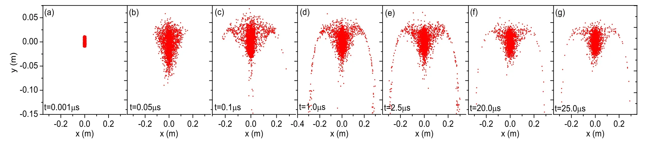
Figure 8.Diagram of SPs distribution at different times.(a) t=0.001 μs, (b) t=0.05 μs, (c) t=0.1 μs, (d) t=1.0 μs, (e) t=2.5 μs, (f)t=20.0 μs,and(g)t=25.0 μs.In the simulation,the parameters of the proton beam are number density ni0=5.0×10¹⁵ m-3,temperature Ti=5 keV, beam speed V=6.9×10⁵ m s-1 and launch direction θ=85°, respectively.

Figure 9.Diagram of velocity distribution of SPs at different times.(a)t=0.001 μs,(b)t=0.05 μs,(c)t=0.1 μs,(d)t=1.0 μs,(e)t=2.5 μs, (f) t=20.0 μs, and (eg) t=25.0 μs.
4.The dynamic characteristics of proton beam in a bent mirror
In the previous section, we studied the effects of parameters of both the magnetic mirror and the proton beam on the loss rate.In order to further understand how the protons are confined in the magnetic mirror, we study the behaviors of charged particles in a bent mirror in this section.
We now investigate the motion of the protons of the beam in the mirror.As an example,we choose a mirror shown in figure 2 with α=45°.Suppose that the proton beam is at the center of this magnetic mirror initially, the initial number density isni0=5.0 ×10¹⁶m-3,the temperature of the beam is Ti=5 keV, the beam speed is V=vthiand θ=85°.
In order to understand how an initial proton beam evolves with the time in the bent mirror, figure 8 shows the distribution of SPs in the x-y plane at different times t=0.001 μs, 0.05 μs, 0.1 μs, 1.0 μs, 2.5 μs, 20.0 μs and 25.0 μs respectively.It is noted from figure 8 that the protons expand rapidly at the beginning and then most of them are confined by the magnetic field, while some of them leak out of the throat of the magnetic mirror almost along the magnetic field lines.In addition, few of the SPs leak out from the bottom of the magnetic mirror.Figure 8 shows the information about where the protons stay in the mirror and how they leak out the mirror.
The advantage of simulation studies is that it is easy to understand the particle distributions in the velocity space.Figure 9 shows the velocity distribution of SPs at different times t=0.001 μs, 0.05 μs, 0.1 μs, 1.0 μs, 2.5 μs, 20.0 μs and 25.0 μs respectively.It gives us information on how the initial proton beam with non-zero macroscopic velocity evolves into an aggregate of the protons with zero macroscopic velocity.
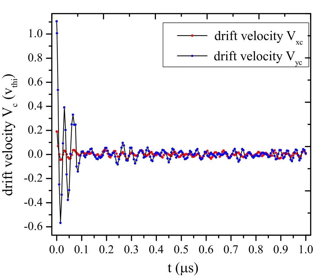
Figure 10.Dependence of drift velocity on time.
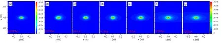
Figure 11.The colour maps of the magnitude of electric fields in the mirror with different times.(a)t=0.001 μs,(b)t=0.05 μs,(c)t=0.1 μs, (d) t=1.0 μs, (e) t=2.5 μs, (f) t=20.0 μs, and (g) t=25.0 μs.

Figure 12.(a) The trajectory of one of the SPs in x-y plane.The initial position and velocity of the SP are (x0, y0)=(-0.01, -0.01)m and(Vx0,Vy0)=(-1.25,0.011)106 m s-1.(b)and(c)The phase diagram of the SP in phase space of(x,Vx)and(y,Vy).(d)and(e)The position(x, y) of the SP as a function of time t.
In order to further understand whether the proton velocity distribution satisfies the Maxwell distribution, the velocity distribution functions of the PIC similational results are compared with the analytical one ofj=x, y.We found that the velocity distribution function of the protons satisfies the drift Maxwell velocity distribution,though the drift velocity is not obvious in figure 9.To further understand how the drift velocity varies with time, the dependence of drift velocity on time is shown in figure 10.Notice that the initial drift velocity is (Vx, Vy)=(0.065,0.984)vthi,which is just the initial beam speed.It is found that the drift velocity oscillates,while its amplitude decreases with time and finally it attends to zero.
We now try to explain why the drift velocity oscillates,but finally becomes zero.When the charged particles are injected into the mirror, the impulses will act on them, and their momentum will be changed according to the theorem of impulse.Then the charged particles will finally oscillate quasi-periodically.Therefore, the average velocity of all charged particles becomes zero due to all the charged particles oscillating quasi-periodically.The oscillation periods of drift velocities are about 0.0335 μs for Vxand 0.0335 μs for Vy.
Figure 11 shows the variations of the magnitude of the electric field with respect to the spatial coordinates x and y.It suggests that the magnitude of the electric field is almost zero at the center of the mirror, while the maximum value of the electric field is found near the center.Moreover, the maximum value of the electric field is larger at the symmetry axis than that out of it.The larger the distance from the axis of symmetry, the less the maximum value of the electric field.
We now try to know how an SP moves in the mirror with α=45°.For this purpose, we give the trajectory of an SP shown in figure 12(a).It seems that the SP vibrates in both x and y directions with different periods.For further study, the phase diagrams of both (x, vx) and (y, vy) are given in figure 12(b) and figure 12(c) respectively.It can be noticed from figures 12(b) and (c) that the SP is moving quasi-periodically in both directions.
In order to quantitatively describe the quasi-periodic motion of the SP, figures 12(d) and (e) show the variations of the SP spatial coordinates of both x and y with respect to time t.The SP moves periodically,but with several periods in both x and y direction.It is noted that there are two main periods (TB1, TB2) in the x direction, corresponding to two reflection motions at the far reflection point (red dot in figure 12(a)) and near reflection point (green dot in figure 12(a)) in the x direction.There are three main periods (TG1, TG2and TG3) in the y direction.It can be noticed from figures 12(d) and (e) thatIt is seen that it takesduring the time when the SP moves from the left reflection point to the right reflection point, while it is just one period, TG1, in the y direction due to the curvature of the magnetic field line.In other words, TG1and TB1are resulted from the curvature of the magnetic field line.However, TG2and TG3are due to the cyclotron motion of the protons, whose frequencies are ωci=eB/mi.Because the magnetic field is not a constant, and the cyclotron frequency is not a constant either.TG2and TG3correspond to the two points.One is at the reflection point,the other is at the point x=0.
In general,there are two periods,TG2,TG3~10-2μs and TB1/TG1, TB2~10-1μs which correspond to two kinds of periodic motion—Lamore cyclotron motion and motion reflected back and forth along the magnetic field line,in other words, two adiabatic invariant—magnetic moment invariant and longitudinal invariant.
5.Conclusions
The proton beam confined in a bent magnetic mirror is studied in the present work by using the PIC simulation method.It is found that the loss rate of the charged particles in a bent mirror is less than that in the axi-symmetric mirror.When the coils deflect at a certain region, the loss rate decreases.But when the deflection angle of the coils is large enough,it is not a magnetic mirror any more and is not discussed further.
As an example,we choose α=45°for the bent mirror and investigate the effect of plasma parameters on the loss rate.It is found that the loss rate reaches maximum values at a certain ion number density when the ion electrostatic oscillation frequency is equal to the ion cyclotron frequency.In addition,the loss rate is irrelevant to the direction of the proton beam.
In order to further understand how the loss rate varies with respect to the system parameters, the ion (SPs) trajectories are studied.It is found that the charged particles mainly escape from the throat of the bent mirror if deflected angle is smaller,such as 30°and 45°,while they escape not only from the throat, but also from the bottom of the bent mirror if α is large enough, such as 60° and 67.5°.It is also found that the velocity distribution function of the protons satisfies drift Maxwell velocity distribution.However, the drift velocity oscillates,while its amplitude decreases with time and finally it attends to about zero.The oscillation periods of drift velocities are also given for velocity components in both the x and y directions.It is concluded that the motion of the charged particles is quasi-periodic.
Our results have potential applications to devise a mirror.For example, we may choose bent mirror to confine charged particles because the loss rate of the bent mirror is less than that of the axi-symmetric mirror.Furthermore,we can choose an appropriate deflection angle to obtain less loss rate.In addition, we have to avoid a certain ion number density at which ion electrostatic oscillation frequency is equal to the ion cyclotron frequency to obtain less loss rate.
Acknowledgments
This work was supported by National Natural Science Foundation of China (Nos.11965019, 42004131).
猜你喜欢
杂志排行
Plasma Science and Technology的其它文章
- A brief review: effects of resonant magnetic perturbation on classical and neoclassical tearing modes in tokamaks
- A classical relativistic hydrodynamical model for strong EM wave-spin plasma interaction
- Analysis of inverse synthetic aperture radar imaging in the presence of time-varying plasma sheath
- Analysis of the influence of sheath positions,flight parameters and incident wave parameters on the wave propagation in plasma sheath
- Transmission characteristics of terahertz Bessel vortex beams through a multi-layered anisotropic magnetized plasma slab
- Measurement and analysis of species distribution in laser-induced ablation plasma of an aluminum–magnesium alloy