Analysis of the influence of sheath positions,flight parameters and incident wave parameters on the wave propagation in plasma sheath
2022-04-15QifanZHANG张启凡YipingHAN韩一平QinluDONG董秦鲁andChangDONG董畅
Qifan ZHANG (张启凡), Yiping HAN (韩一平), Qinlu DONG (董秦鲁) and Chang DONG (董畅)
School of Physics and Optoelectronic Engineering,Xidian University,Xi’an 710071,People’s Republic of China
Abstract The plasma sheath covering hypersonic vehicles has a significant effect on the propagation of electromagnetic waves.Based on the calculation of the flow field of a conical cylindrical, this work studies the propagation of electromagnetic waves in plasma sheath at L-band and Ku-band,and discusses the propagation characteristics in the head, side and tail of the sheath.The dielectric properties of plasma sheath are related to flight speed and altitude.A flight condition corresponds to a unique distribution of dielectric properties.For the conical cylindrical, the results show that flight speed is generally negatively correlated with the transmissivity of the plasma sheath.The reflection characteristics of electromagnetic waves at the L-band and Kuband when obliquely incident to the plasma sheath show a downward trend.When the frequency is increased to Ku-band,the propagation characteristics of electromagnetic waves in the plasma sheath are related to the position of the sheath.
Keywords: plasma sheath, reflection and transmission, flow field
1.Introduction
When a hypersonic vehicle performs a mission or reenters at a speed greater than 5 Mach in the atmospheric environment(generally about 20–80 km),due to the super high speed of the vehicle,shock waves are formed at the front of it,accompanied by high-temperature effects.When the temperature rises to thousands of Kelvin, the air will react to chemical reactions such as dissociation and ionization, forming a plasma environment around the vehicle.Generally,the plasma formed by high-speed flight surrounding the vehicle is called a plasma sheath.The properties of plasma sheath are mainly related to flight speed and height.The existence of a plasma sheath will cause obstacles to the communication between the navigation system and the vehicle.When the navigation system cannot detect the vehicle due to the influence of plasma sheath,it will cause communication problems, which is called the ‘black barrier’of communication.
The propagation of electromagnetic waves in plasma sheath involves two key issues:the calculation of propagation and the distribution of the dielectric properties of plasma sheath converted from the flow field.Regarding the propagation of electromagnetic waves in plasma, many studies are based on the propagation of electromagnetic waves in plasma and the measurement of electromagnetic pulses emitted in experiments.The electromagnetic calculation in the plasma sheath of the hypersonic vehicle involves less.In the 1960s,Haskell and Case gave the long-term transient response of the lossless anisotropic plasma to short electromagnetic pulses[1].In the 1970s, Satorius studied the propagation of electromagnetic pulses through nonlinear, cold and collisionfree plasma[2].In the 1990s,Destler et al published an article[3] to study the transmission and absorption of planar highpower microwave pulses covered by plasma.Kinefuchi et al[4] combined the ionized exhaust plumes of a rocket engine with the propagation of radio frequency electromagnetic waves in the plasma.In 2011, an IEEE paper [5] used an empirical formula of plasma frequency and collision frequency about temperature and other flow field parameters to calculate the transmission of electromagnetic waves in plasma sheath.It pointed out that there was a severely attenuated frequency band.Zheng [6] combined shock tubes to conduct experimental research on the propagation characteristics of electromagnetic waves in plasma.In 2016, Takahashi from Japan[7]combined the RAM-C model to analyze the loss of electromagnetic waves passing through the plasma sheath covering the vehicle at the same speed and different flight altitudes.
The flow field of the plasma sheath is usually calculated by numerical methods.The dielectric characteristic distribution of plasma sheath is obtained by parameter conversion.Fante used the transport method to study the problem of narrow-angle beams passing through turbulent plasma [8].In 2018, Wang and Ma from the Air Guided Missile Research Institute [9] numerically solved the complex permittivity distribution of the hypersonic cone target sheath.In addition,the interaction between electromagnetic waves and plasma sheath also includes the scattering characteristics.In 2011,Sotnikov, Leboeuf and Mudaliar published an article [10] to study the scattering characteristics of electromagnetic waves in velocity-excited turbulent plasma.Later, Bian et al published an article on the dynamic plasma sheath of hypersonic vehicles [11], based on the detection platform of spaceborne radar,calculating the scattering of the dynamic plasma sheath,which provides a reference for the classification and recognition of targets.
In order to discuss the influence of plasma sheath covering hypersonic vehicles on the propagation of electromagnetic waves, this work takes the power reflection and transmission of the plane electromagnetic wave incident on plasma sheath as parameters to discuss the propagation characteristics.This work combines the propagation of electromagnetic waves in plasma with the flow field of the sheath,and analyzes the influence of different factors such as sheath positions, flight parameters and incident wave parameters on the propagation characteristics of electromagnetic waves in plasma sheath.
The propagation characteristics of electromagnetic waves in plasma sheath are closely related to the frequency of electromagnetic waves.Araszkiewicz and Kiliszek discussed some of the navigation system operating frequencies in [12],which illustrated that most of the more mature frequencies used by global navigation systems were concentrated at the L-band.Table 1 lists some bands of several major navigation systems.
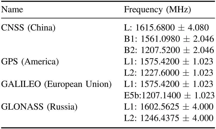
Table 1.Operating frequency bands of several navigation systems.
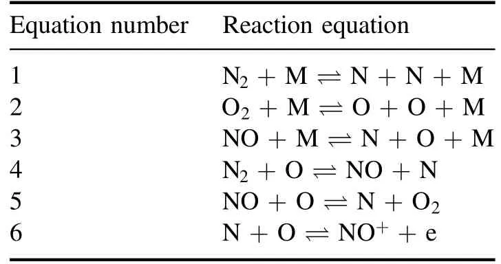
Table 2.Chemical reaction equation of the 7-component model.

Table 3.Calculation conditions of the flow field.
The operating frequency band of the navigation system is relatively dense at L-band and has a wide range of applications.Many countries are also actively carrying out higherfrequency navigation study.In addition, the frequency bands of communication for satellites also include Ku-band.Higher band links have faster transmission rates, which can also provide support for the integration of navigation and remote sensing.
2.Description of plasma sheath and calculation method of propagation characteristics
2.1.Drude model of dispersive medium
Plasma is a dispersive medium.In this work,the Drude model is used to describe the dispersive characteristics of plasma.The relative permittivityεrof the Drude model can be described by the formula (1)
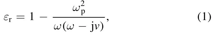
whereωp,vandωrepresent plasma frequency, collision frequency and incident electromagnetic wave frequency.If the plasma frequency and collision frequency of the plasma are known, the corresponding relative permittivity can be calculated.It can be said that the properties of plasma are fundamentally determined by plasma frequency and collision frequency.
The relative permittivity of plasma is a complex number.The real and imaginary parts of the complex number represent different properties.Sorting the real part and imaginary part of formula (1)separately,it can be expressed in formula (2)
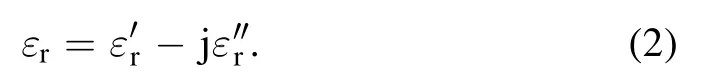
In formula (2), the real part of the complex relative permittivity represents the dielectric constant, and the imaginary part represents the loss of the medium.The expressions of the real part and the imaginary part are as the following expression

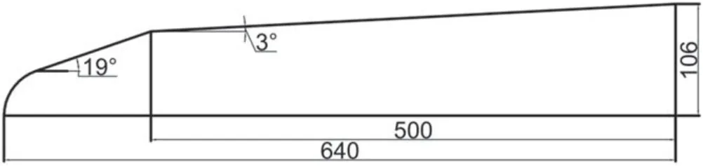
Figure 1.The calculation model of this work (unit: mm).
2.2.The flow field of sheath and its conversion with plasma parameters
2.2.1.Flow field of a hypersonic conical cylinder.The calculation model in this article is a conical cylinder.Because of its symmetrical structure, the schematic figure is shown in figure 1.This work calculates the thermochemical non-equilibrium flow field around the hypersonic vehicle.The mature 7-component model is used to analyze the flow field,which provides data support for the electromagnetic calculation of plasma sheath.The main reaction equations of the 7-component model are shown in table 2 below.M represents a catalytic body.
To illustrate the reliability of the flow field calculation,figure 2 simulates the flow field of RAM-CII, which was the model of the US flight test.The comparison of temperature changes on the stagnation point line between the calculated results and [13] is shown in figure 2 below.The flying speed is 25.9 Mach; the flying height is 71 km.The incoming flow velocity is about 7636 m s-1,the pressure and temperature of the space are 19.85 Pa and 254 K, respectively.
It can be seen that the temperature curve is consistent with the trend of [13], and the order of magnitude is comparable, which verifies the reliability of the flow field calculation method.
In order to analyze the propagation characteristics of electromagnetic waves in plasma sheath under different flight states, three flight states are selected in this work, which are listed in table 3.
The flow field of the hypersonic vehicle is calculated numerically with three flight states, and the results obtained are shown in figure 3 below.The hypersonic model is the white area in the figure,and the flow field of the sheath is the outer area.For example,to flight state 1,the temperature and pressure distributions of the flow field of the wrapped cone cylinder are as figure 3.
It can be seen that the temperature of the sheath flow field is mostly thousands of Kelvin.When the flying altitude is 30 km and the speed is 12 Mach,the temperature of the head of the conical cylinder can reach 4500 K.The pressure can reach 220 kPa.
2.2.2.Parameters conversion.The flow field parameters and plasma parameters such as frequency and collision frequency need to be converted for electromagnetic calculation.The transformation process requires parameters such as temperature, the number density of neutral particles and the collision cross section of various neutral particle energy conversions.The plasma frequency is the sum of the plasma frequencies of electrons and ions in the plasma,which can be described by expression (4)
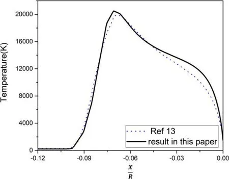
Figure 2.Comparison of temperature changes on the stagnation point line.

The main difference between the plasma frequency of electrons and ions lies in the difference between the mass of electrons and ions.Since the mass of ions is much higher than that of electrons, the expression (4) can be simplified as expression (5)
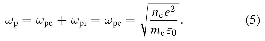
In the above formula,except for the electron number density,the other three quantities are all constants.The plasma frequency can be calculated from the electron number density.The electron number density can be obtained from the flow field.
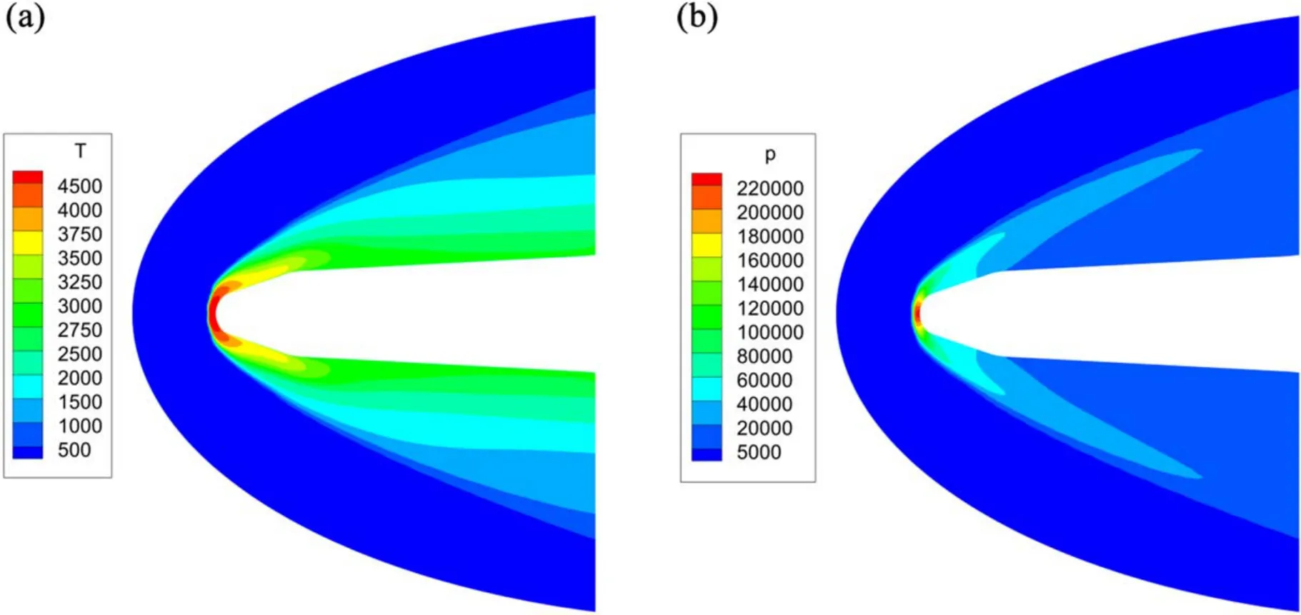
Figure 3.The flow field distributions of a conical cylindrical at H=30 km,V=12 Mach.(a)The distribution of temperature(K).(b)The distribution of pressure (Pa).

Figure 4.The plasma parameter distributions of the sheath at H=30 km,V=12 Mach.(a)The distribution of plasma frequency(Hz).(b)The distribution of collision frequency (Hz).
The collision frequency involves the collision process of neutral particles, electrons and ions on the microscopic level.The collision frequency is not only related to the collision rate, but also to the energy transfer rate and loss of the collision process.It is a relatively complex process.The collision process in plasma sheath is mainly caused by the collision of electrons.According to the research of related scholars,the collision frequency in the plasma is summarized as the expression (6) [14]
niis the number density of neutral particle i,Qiis the collision cross section of the effective electron-neutral particle energy conversion of component i,which is a function of the electron temperature.The parameters of the conversion collision frequency in the expression can be obtained from the flow field.After obtaining the parameters of each component,the plasma parameters at different positions of the sheath can be obtained systematically.It can be said that the flow field distribution is the basis of the electromagnetic calculation of plasma sheath.
The conversion result of figure 3 is shown in figure 4.The plasma frequency of the conical cylinder flow field can reach 32 GHz.The collision frequency can reach 0.16 THz.The collision frequency is numerically greater than the plasma frequency.
2.3.Calculation method of propagation characteristics of plasma sheath
After obtaining the plasma frequency and collision frequency distribution of the plasma sheath, we need to extract the plasma frequency and collision frequency of the calculated positions.Then, according to the plasma frequency and collision frequency,the thickness is non-uniformly layered.Each layer of the medium will have a plasma thickness and a set of plasma parameters after that operation.After completing the layering of the plasma sheath under the variable thickness,the layered model can be used to calculate the transmission of electromagnetic waves at different positions.The following figure 5 drawn by authors can be used to illustrate the electromagnetic wave incident to the layered medium model.

Figure 5.The calculation method of this work.
Finite-difference time-domain (FDTD) solutions based on the FDTD method.The FDTD method was used to calculate the propagation of electromagnetic waves in layered media.According to the above-mentioned layered medium model,assuming that the XOY plane is selected as the incident surface,taking transverse magnetic waves as an example,the field components of TM waves are simplified to three components (Ez,Hx,Hy).The frequency domain form of the Maxwell equation can be expressed as the following equation
Converting expression (7) to the time domain form, we can obtain the expression (8)

In formula (8),rεrepresents the relative permittivity.
According to the dominant equation and the phase matching principle of the tangentially continuous wave vector at the interface of the layered medium,the propagation problem of the electromagnetic wave in the medium can be solved after knowing the incident direction of the electromagnetic wave[15].
Knowing the equations, the step recursive expressions forEz→Hx,Ez→Hycan be obtained by the FDTD discretization of the first two equations in equation (8).Assuming that the electromagnetic wave incident on the layered plasma medium is time-harmonic wave, the incident angle isθand the incident surface is the XOY plane, then its form can be expressed asEz(x,y,t)=E0exp [ j(k xx+k yy+ωt)].According to the incident wave form, we can know∂/∂x→jkx=jk0sinθ.
Taking the derivative of both sides of the second formula of (7) with respect to x at the same time, we can get
Combining the third formula of(7),we can get the following expression
Its time domain form is

Combining the first two formulas of (8) and (11) can realize the step calculation forEz→Hx→Ez.
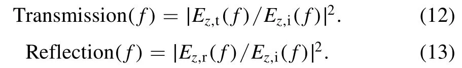
In the calculation process,the incident electric feildEz,i, the reflected electric fieldEz,rand the transmitted electric fieldEz,tare recorded.The Fourier transform is performed respectively to obtain the transmissivity and reflectivity of the electromagnetic wave incident on the plasma sheath.For the plane wave, the transmission and reflection of incident electromagnetic wave energy can be expressed by the formulas(12)and(13),where f represents the frequency of the electromagnetic wave
In the calculation,take 1/18 of the wavelength as the mesh length.The distance of the absorption boundary from the model is greater than half of the calculated maximum wavelength.
The reliability of the calculation results in this work can be verified with the following example.About the oblique incidence of electromagnetic waves in plasma, Chen et al have published related calculation results in their papers[16, 17].The comparison and verification of the calculation results show the reliability of the calculation.The incident angle was 30°.The comparison result is shown in figure 6.
The red asterisk line in figure 6 is the result of the calculation in this work.It can be seen that the two results fit well.The calculation method can be considered feasible.
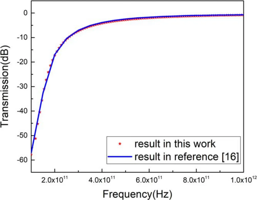
Figure 6.Comparison of different methods for the same transmission problem.Calculation conditions: wave frequency is 0.1–1 THz,electron number density is 1.8 ×10 20m- 3,collision frequency is 5 ×10¹¹Hz, the thickness of plasma is 5 mm.
3.Propagation of electromagnetic waves in plasma sheath
3.1.Selection of the incident position
The dielectric properties of the plasma sheath are different at different positions, and electromagnetic waves have different propagation characteristics at different positions of the sheath.The authors selected three different positions of the sheath.The schematic diagram of their positions is shown in figure 7.
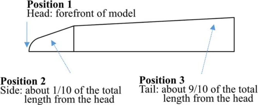
Figure 7.Three different positions of the electromagnetic wave incident on the sheath.
Three positions are position 1, position 2 and position 3,which represent the head position, side position and tail position of the plasma sheath respectively.
3.2.Effect of the position of plasma sheath
Taking the flying height of 30 km,the speed of 12 Mach,the electromagnetic wave is incident perpendicularly and the frequency band is L-band as an example, the propagation calculation results are as figure 8.
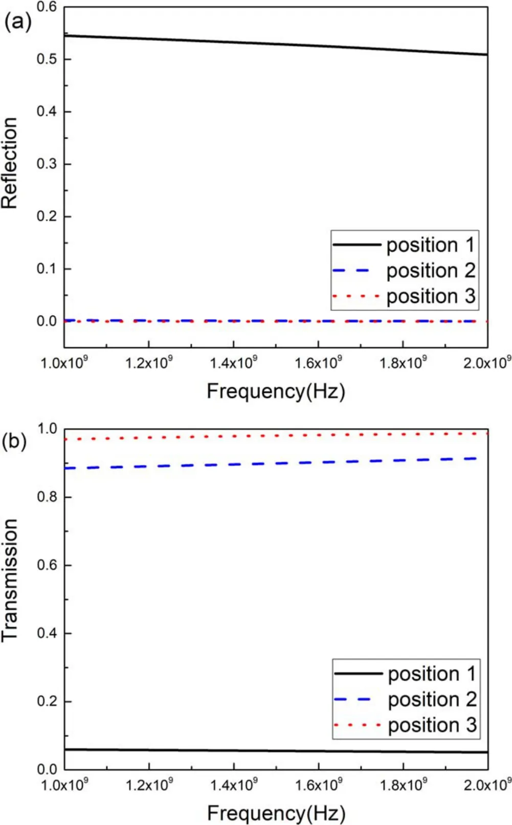
Figure 8.The effect by the positions of the plasma sheath of L-band electromagnetic waves propagation characteristics.(a) Reflection.(b) Transmission.
Under this condition, the propagation of electromagnetic waves in the plasma sheath is related to the position of the sheath.The head position is the position where the reflection of electromagnetic waves is strongest and the electromagnetic waves cannot pass through the plasma sheath at the head position.Due to the intensity of the interaction between the flow and vehicle,electromagnetic waves can pass through the plasma sheaths at the side and tails under the same conditions.
3.3.Effect of the incident angle
When the height is 30 km and the speed is 12 Mach, the calculation results at L-band of the vertical incidence and oblique incidence angle of 30° are shown in figure 9 (I_A is the incident angle.)

Figure 9.The effect by the incident angle of L-band electromagnetic waves propagation characteristics.(a) The head position of the plasma sheath.(b) The side position of the plasma sheath.(c) The tail position of the plasma sheath.
It can be seen from figure 9 that the energy of the reflected electromagnetic wave is reduced at the three positions by increasing the incident angle.The energy of the transmitted electromagnetic wave is related to the position of the sheath.The transmission at the head position is slightly increased,but the transmission at the tail and side positions is reduced.When the electromagnetic wave propagates in the plasma sheath, there will be absorption loss of the medium,which is the reason for the decrease of the transmission of the side and tail of the plasma sheath.
3.4.Effect of the flight parameters
For example to the side(position 2)of the plasma sheath and the vertical incidence of L-band electromagnetic waves, the results under three flight conditions are shown in figure 10.Both reflection and transmission characteristics are closely related to flight conditions.Even if electromagnetic waves are partially reflected, it does not indicate that electromagnetic waves can pass through the plasma sheath for sure.When the flying altitude is 30 km and the speed is 18 Mach, after interaction with the plasma, the wave is totally reflected and it cannot pass through the sheath.When the flying altitude reaches 60 km, the reflection of electromagnetic waves by the sheath is reduced, but due to the attenuation of energy, it still cannot pass through the sheath.Compared with the flight altitude of 30 km and the speed of 18 Mach, when the flight speed is reduced to 12 Mach, the sheath has a better transmissivity in this situation.
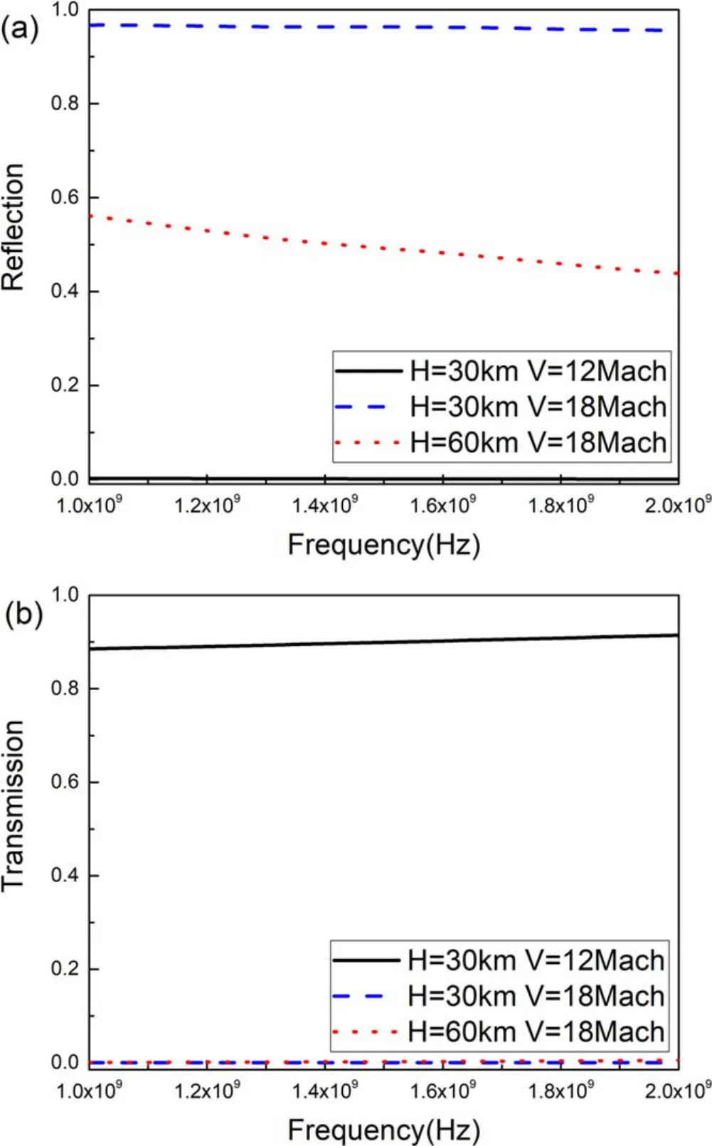
Figure 10.The effect by the flight parameters of L-bandelectromagnetic waves propagation characteristics.(a) Reflection.(b) Transmission.
3.5.Effect of the electromagnetic wave band
The electromagnetic frequency band of communication and application for navigation systems is not limited to L-band,Ku-band navigation and communication are also adopted.Compared with L-band, when the frequency of electromagnetic waves increases to the Ku-band, for example to the flight at H=30 km, V=18 Mach and the side position of the plasma sheath, the calculation results of reflection and transmission are as figure 11.
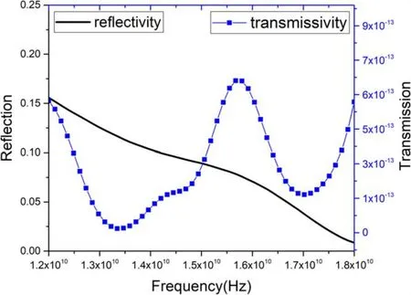
Figure 11.The reflection and transmission of the flight at H=30 km,V=18 Mach and the side position of the plasma sheath at Ku-band when an electromagnetic wave is incident on the plasma sheath vertically.
Compared with the blue dash lines in figure 10, the energy of reflected electromagnetic waves at position 2 decreases significantly when the frequency rises to Ku-band.Combined with the transmission characteristics,it can be seen that electromagnetic waves still cannot pass through the plasma sheath.However,when the frequency rises to the Kuband, the change of the propagation characteristics is also related to the position of the sheath.The change of the propagation characteristics at this position cannot be applied to all situations.
4.Conclusion
This work studies the propagation of different bands of electromagnetic waves incident on the plasma sheath of a conical cylinder at different positions.The results show that,regardless of L-band or Ku-band, the propagation characteristics of the head position of the sheath are always worse than those of the side and tail positions.At the L-band,the tail and the side positions reflect less electromagnetic waves than the head position, and at these two positions, when the electromagnetic wave is incident obliquely,the reflection decreases,and the transmission performance increases.When the flight speed increases, the loss of the plasma sheath increases,which is more unfavorable to the propagation of electromagnetic waves.Contrary to the influence of flight speed on the transmission characteristics, when the flight altitude is increased to 60 km, the transmission performance of the sheath is slightly enhanced at the same flight speed.When the frequency increases to the Ku-band, the reflection and transmission of electromagnetic waves by the sheath are related to the position of the sheath.
This work has certain significance for studying the propagation of electromagnetic waves in the plasma sheath and it is helpful to the communication with hypersonic vehicles.
杂志排行

Plasma Science and Technology的其它文章
- A brief review: effects of resonant magnetic perturbation on classical and neoclassical tearing modes in tokamaks
- A classical relativistic hydrodynamical model for strong EM wave-spin plasma interaction
- Analysis of inverse synthetic aperture radar imaging in the presence of time-varying plasma sheath
- Transmission characteristics of terahertz Bessel vortex beams through a multi-layered anisotropic magnetized plasma slab
- Measurement and analysis of species distribution in laser-induced ablation plasma of an aluminum–magnesium alloy
- Free-boundary plasma equilibria with toroidal plasma flows