Three-step self-calibrating generalized phase-shifting interferometry
2022-03-12YuZhang张宇
Yu Zhang(张宇)
1Institute of Materials Physics,College of Science,Northeast Electric Power University,Jilin 132012,China
2State Key Laboratory of Applied Optics,Changchun Institute of Optics,Fine Mechanics and Physics,Chinese Academy of Sciences,Changchun 130022,China
Keywords: self-calibrating generalized phase-shifting interferomertry,phase shift,difference interferograms,modulation amplitude
1. Introduction
Self-calibrating generalized phase-shifting interferometry(SGPSI) is a technique for extracting the phase map from three or more phase-shifting interferograms without knowing the phase shifts.[1]It removes the restriction that accurate phase-shifting interferometry (PSI) needs accurate phase shifter,thus,it has been widely used in high precision optical metrology. Over the past few decades, many ingenious SGPSIs have been developed,and they can be divided into iterative and non-iterative ones.[2]
Among the iterative SGPSIs,an overdetermined approach that uses least-squares algorithms has been studied extensively for randomly phase-shifting interferograms. In 2004, Wang proposed an advanced iterative algorithm (AIA), which can obtain accurate phase distribution from more than three randomly phase-shifting interferograms.[3]It resolves the limitation of the existing iterative phase-shifting algorithms(PSAs)and separates the frame-to-frame iteration from the pixel-topixel iteration. After that,many iterative PSAs based on AIA were proposed. In 2008,a new generalized iterative algorithm for extracting phase distribution from randomly and spatially nonuniform phase-shifting interferograms was proposed,it requires only four randomly phase-shifting interferograms, and finally an accurate phase map is extracted by reducing the effects of transition and tilt errors.[4]In 2019,Chenet al.evaluated the performance of AIA,and proposed an enhanced AIA(eAIA)which can control the phase shifts,frame numbers and suppress noise.[5]In general, the iterative SGPSI is relatively accurate, but the convergence of the algorithm requires more time. Moreover,a moderate number of interferograms are required to ensure high performance.
To save time,lots of non-iterative SGPSIs have been developed. In 2011, Vargaset al.designed a well-evaluated PSI based on the principal component analysis(PCA),which can obtain two orthogonal signals by PCA. It is very fast and requires very low computational requirements, so it can be used for very large images or very large image sets.[6]In 2015, Denget al.presented an advanced principal component analysis method, two difference maps were obtained by a simple subtraction operation easily, and then the phase can be calculated by the traditional PCA.[7]From 2016 to 2017, Yatabeet al. proposed a series of PSAs based on PCA which can accurately extract the phase by integrating spatial information.[8-10]PCA is very fast, however, it needs to subtract the background intensity by acquiring more than three phase-shifting interferograms, and the phase shift should be well distributed between 0 and 2π. In addition, PCA needs to confirm the sign of the phase by extra method. In 2014,Wanget al. designed an advanced Gram-Schmidt orthonormalization algorithm(GS3),it needs only three phase-shifting interferograms. Although it costs less time than PCA, its accuracy is lower than PCA with more than three phase-shifting interferograms.[11]Non-iterative SGPSIs cost less time,however,their accuracies are lower than that of iterative SGPSIs.
Note that all these SGPSIs here can only deal with accuracy or computational time problem, and they are hard to get high accuracy and high speed at the same time. In order to balance the speed and accuracy,it is essential to study the fast and accurate SGPSI.
In this paper,a fast and accurate three-step SGPSI to cope with the above problems is proposed.We first discuss the principles of the proposed method and then give its verification by computer simulations and experiments. Moreover, we compare the proposed method with AIA, PCA and GS3 to verify its outstanding performance.
2. Algorithm description
The expression of theithframe phase-shifting interferogram is

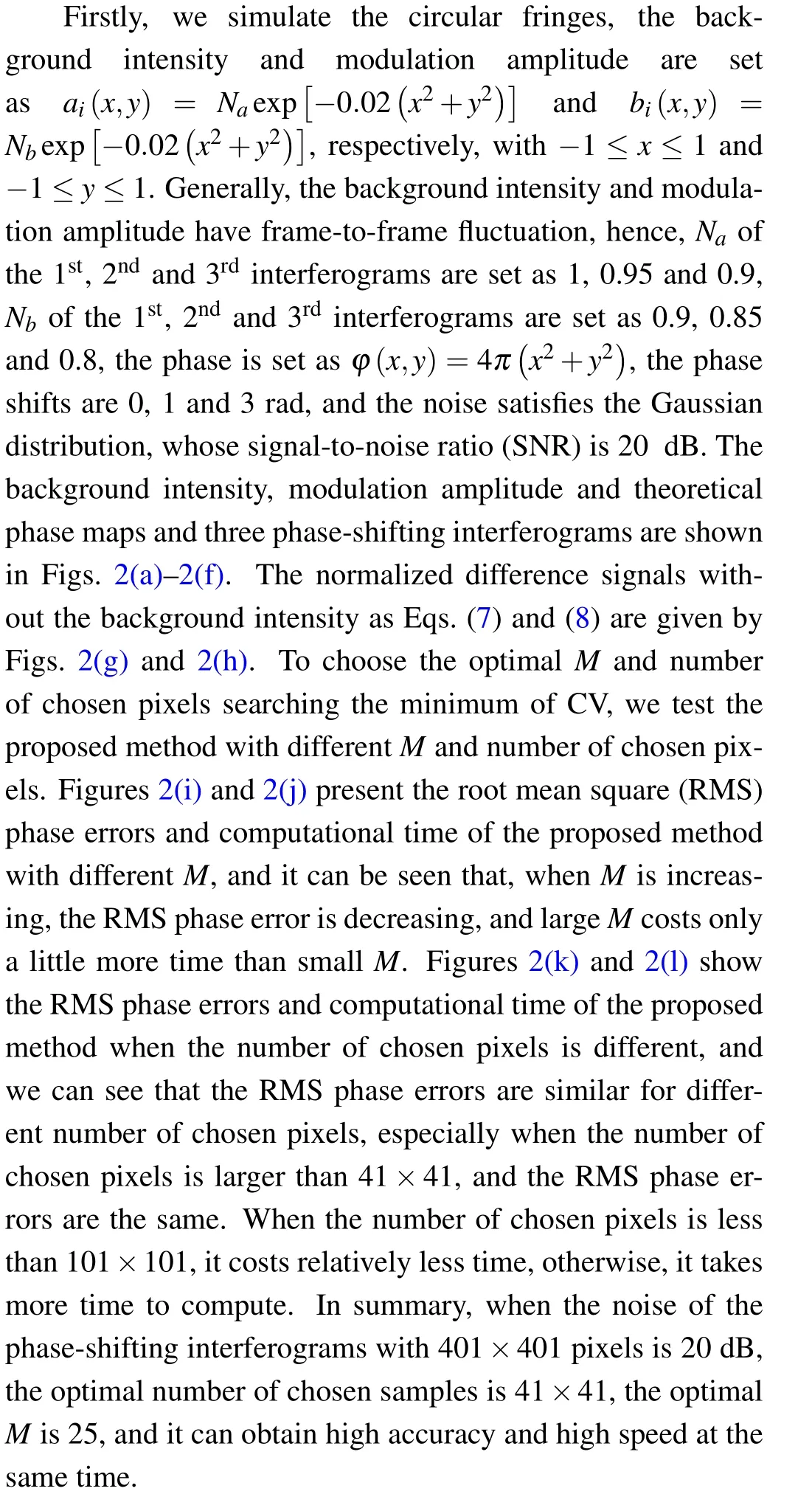
whereai(x,y) andbi(x,y) respectively represent the background intensity and modulation amplitude of the interferograms,φ(x,y)is the tested phase,θiis the phase shift,irepresents the image index(i=1, 2, 3), and the size of interferograms isNx×Ny.θ1can be considered to be zero without losing generality. The spatial coordinates have been omitted below for convenience.
Firstly, we implement the subtraction between the 1stphase-shifting interferogram and theithphase-shifting interferogram. Generally for the background intensity and modulation amplitude distributions, both the fluctuation between different interferograms and the non-uniformity between different pixels exist,however,the subtraction can still filter most of the background intensity. Hence,for simplicity,we assume thatai(x,y)andbi(x,y)are irrelevant to the image index,and only relevant to the pixel position in the subtraction process.
We calculate the intensity of difference maps between the 1stphase-shifting interferogram and theithphase-shifting interferogram as
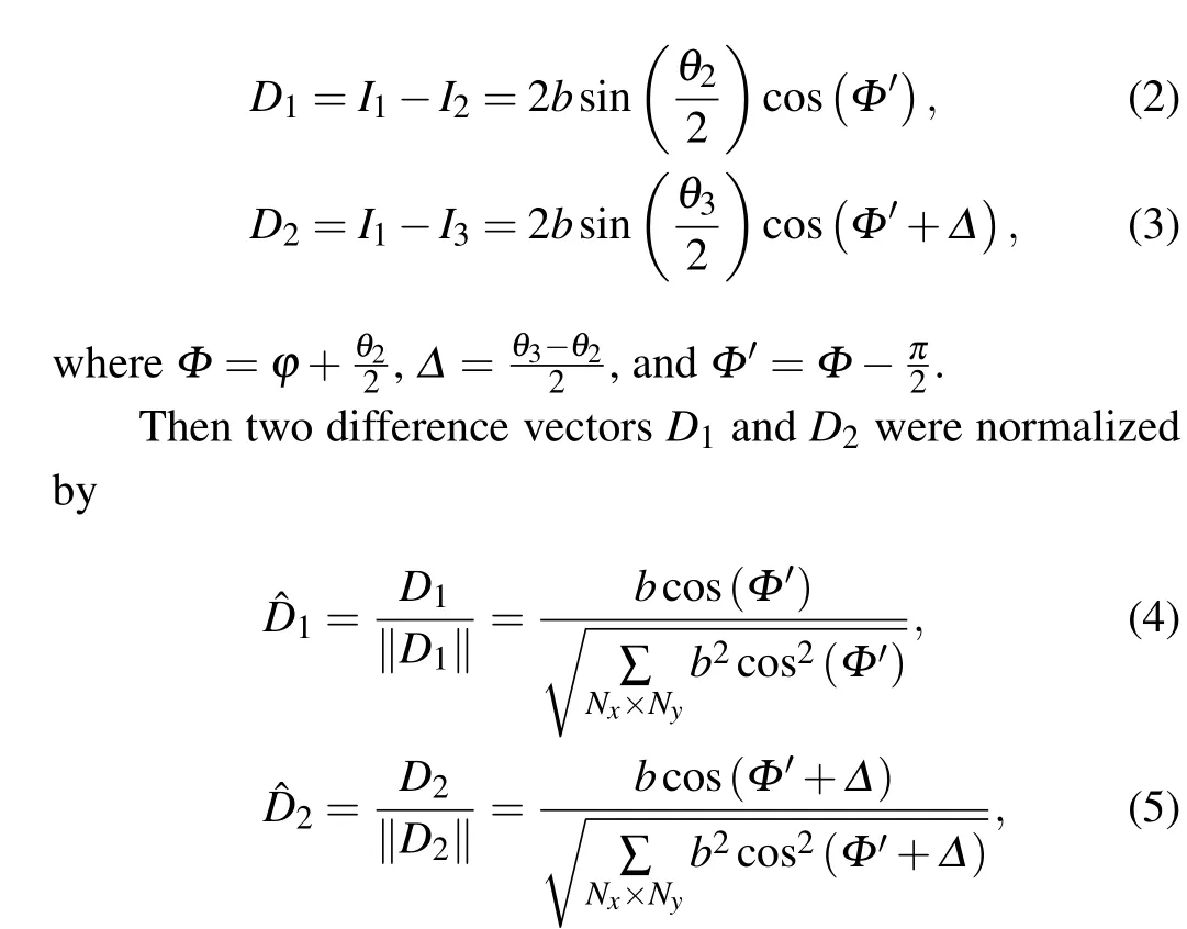
where‖·‖represents the 2-norm.

Here ˆD1and ˆD2can be considered as two phase-shifting interference signals with no background intensity,Δis the phase shift,andcrepresents the new modulation amplitude. The difference betweenφandΦ′is a constant,which does not affect the phase distribution,soΦ′can express the tested phase. Because of the fluctuation,non-uniformity of the original modulation amplitudeband the approximation error of Eq.(6),the new modulation amplitudecis both relevant to the pixel position and image index. Hence Eqs. (7) and (8) are rewritten as

wherem=1, 2 denotes the index of the new phase-shifting interference signals,Δ1=0 andΔ2=Δ.
To depress the noise, we use the mean of the adjacent pixels to generate the new pixel, then the new phase-shifting interferograms are generated. The distribution diagram of the adjacent pixels is shown in Fig. 1, andMis the number of adjacent pixels.
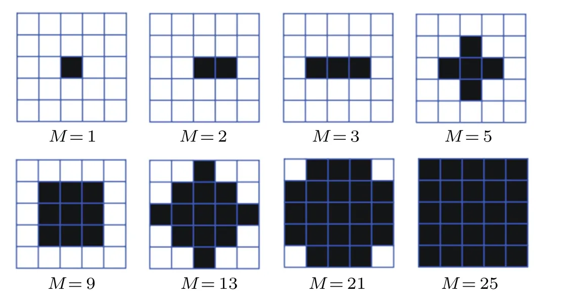
Fig.1. Distribution diagram of the adjacent pixels.
Note that the boundary of new phase-shifting interference signals must be extended properly so thatMadjacent pixels are valid, such as ˆDm(Nx+1,Ny) is out of the range.According to the above eight situations in Fig. 1, we extend the size of the normalized difference maps fromNx×Nyto(Nx+4)×(Ny+4). The values of the 1stand the 2ndrows for the extended maps with the size of(Nx+4)×(Ny+4)are the same as that of the 1strow for the original maps with the size ofNx×Ny. The values of the(Nx+3)thand the(Nx+4)throws for the extended maps are the same as that of theNthxrow for the original maps. Moreover, the values of the 3rdto the(Nx+2)throws for the extended maps are the same as that of the 1stto the (Nx)throws for the original maps. Finally, the extension of the column is the same as the row.
The expression of the new phase-shifting interferograms can be written as
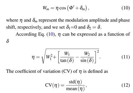
where std(·) denotes the standard deviation, and mean(·) denotes the mean value.The normalization to the mean can make this quantity independent of different measurements. According to Eq.(12),CV can be used as a parameter to evaluate the variation of the modulation amplitudeη.ηwill be irrelevant to the pixel position and image index ideally. However, because of the fluctuation, non-uniformity of the original modulation amplitudeb, the approximation error of Eq. (6) and noise depression error,ηis both relevant to the pixel position and image index. Althoughηis not a constant for different pixel positions,the difference between different pixels will also be very small. Hence,when the phase shiftδis accurate,ηis also accurate,and CV will be minimum,so the phase shiftδcan be determined through searching the minimum of CV,

In order to further save time,a limited of pixels with equal interval can be chosen to take part in the searching process.
3. Simulation verification
The validity of the proposed method have been verified by the numerical simulations. In the following,all computations are performed with the CPU of Intel(R) Core(TM) i5-8265U and the 8 GB memory, and we use the Matlab software for coding.
Figures 2(m)and 2(n)present the new phase-shifting interferograms after suppressing the noise as Fig. 1 (M=25),and we can see that the new phase-shifting interferograms are more clear than the original phase-shifting interferograms.After calculating the CV of the modulation amplitude with different phase shifts(the number of chosen samples is 41×41),Fig. 2(o) is obtained, and the phase shift between Figs. 2(m)and 2(n)corresponding to the valley can be just used to rebuild the phase map. The rebuilt phase map using the found phase shift and phase error map are given in Fig. 2(p) (note that,there are two steps to obtain the phase error map, firstly, we implement the subtraction between the rebuilt phase map and theoretical phase map,then we subtract the minimum from the existing phase error map),and the results of AIA method and PCA/GS3 method are shown in Figs.2(q)and 2(r). We calculate the RMS of phase error and computational time,as listed in Table 1. From Figs. 2(p)-2(r) and Table 1, it can be seen that the accuracy of the proposed method is higher than that of AIA, PCA and GS3, and it costs relatively less time, the accuracy of PCA and GS3 are same,but GS3 costs less time.
We also study the effect of noise to the optimalM, and the number of chosen pixels is 41×41. Figure 2(s)shows the results, and it can be seen that, if the SNR is 20 dB,whenMis increasing,the phase error is decreasing,and for other situations,whenMis equal to 2,the phase error is maximum due to the asymmetric error of the adjacent pixels(see Fig.1). In fact,for any level of noise,the asymmetric error always exists whenMis equal to 2,however,the effect of 20 dB of noise is larger than that of the asymmetric error. In the actual experiments,the level of noise is unknown,so it is best not to setMequal to 2 to avoid the effect of asymmetric error. In addition,if the SNR is greater than 30 dB, the phase error whenMis equal to 3 is minimum. Therefore,it can be concluded that the optimalMis 25 when the SNR is 20 dB,and the optimalMis 3 if the SNR is greater than 30 dB.Although the optimalMis different for different levels of noise,whenMis equal to 3,the phase error with 20 dB noise is also relatively small,therefore,3 can be chosen as the commonMin different cases.

Fig. 2. Illustration of the proposed method with simulated circular fringes. (a) and (b) Background intensity and modulation amplitude maps. (c)Theoretical phase map. (d)-(f)Three simulated interferograms(size: 401×401)with phase shifts θ =(0,1,3)rad. (g)and(h)Normalized difference signals as Eqs. (7) and (8). (i) and (j) RMS phase errors and computational time with different M. (k) and (l) RMS phase errors and computational time with different number of chosen pixels. (m)and(n)New phase-shifting interference signals of Eq.(10). (o)Coefficients of variation calculated by Eq.(12). (p)-(r)Reconstructed phase maps and phase error maps from the proposed,AIA,and PCA/GS3 methods,respectively. (s)RMS phase errors with different M for different levels of noise.
It is interesting to analyze the performance of the proposed method,AIA,PCA and GS3 with various phase shifts.For the proposed method,Mis chosen as 25, the number of chosen pixels is 41×41, and other conditions remain unchanged as the circular fringes. The phase shifts of the 1stand 2ndphase-shifting interference signals remain the same, and the phase shift of the 3rdphase-shifting signal is changed from 1.3 rad to 6.0 rad. Figure 3(a)shows the results,and it can be seen that the phase error varies with the change of the phase shift with regard to different methods,and the closer to 1.3 rad and 6 rad,the larger the RMS phase error is,when the practical phase shift(θ3-θ2)/2 is close to 0 rad orπrad,and the RMS phase error will be significantly large.In addition,the range of phase shift of the proposed method is larger than that of other methods. In the whole range of phase shift, the accuracy of the proposed method is higher than that of other methods,and the accuracies of AIA and PCA/GS3 are similar for most of the phase shifts. Moreover, we also simulate the situation of small phase shifts,such as the phase shifts are set as 0,0.1 rad and 0.2 rad. When the SNR of noise is greater than 50 dB,all methods work,otherwise,they do not work because of the large noise. In the actual experiment, the noise distribution is more complex and must exist, so very small phase shifts are not suitable for general methods, including the proposed method. In the future work,we may find or study a method to slove this problem.[12]
We also test the proposed method at different levels of noise in Fig. 3(b), compared with the current well-evaluated SGPSI. The accuracy of the proposed method is higher than that of AIA, PCA/GS3, and they are almost stable for different levels of noise. If the SNR of noise is less than 40 dB,the RMS phase error of AIA,PCA/GS3 is decreasing with the decrease of the noise, and if the SNR of noise is greater than 40 dB,they are all stable. Moreover,the RMS phase error of PCA/GS3 is large as AIA when the noise is large,but it can be similar to the proposed method if the SNR of noise is greater than 40 dB.From the above analysis,we can conclude that the proposed method is more insensitive to the noise,and suitable for any levels of noise.
As mentioned before Eq. (6), the proposed method requires more than one fringe in the interferograms. In fact, if the number of fringes is less than one,the phase error may be relatively large, but it can also reconstruct the phase distribution. To verify this point, we compute the RMS phase errors with different number of fringes from 0 to 4, and the other parameters are same as Figs. 2(d)-2(f). Figure 3(c) presents the results,the RMS phase errors of all methods are almost invariable if the number of fringes is larger than one. However,when there is less than one fringe in the interferograms, the performance of AIA, PCA/GS3 gets worse. By contrast, the proposed method always performs well.
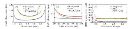
Fig. 3. Comparisons on the RMS phase errors between different methods. (a) RMS phase errors with different phase shifts θ3 (θ1 =0,θ2=1 rad). (b)RMS phase errors with different levels of noise. (c)RMS phase errors with different number of fringes.
We also simulate the complex fringes,the phase is set asφ(x,y)=4x2+4y2+4x3+4y3+4peaks(401),other conditions are the same as the circular fringes,and finally the conclusion is the same as the circular fringes. As shown in Fig.4 and Table 1,we can conclude that the proposed method is accurate and efficient for different kinds of fringes.

Fig. 4. Illustration of the proposed method with simulated complex fringes. (a)-(c) Three simulated interferograms (size: 401×401) with phase shifts θ =(0,1,3) rad. (d) Theoretical phase map. (e) and (f) Normalized difference signals as Eqs. (7) and (8). (g) and (h) New phase-shifting interference signals of Eq.(10). (i)Coefficients of variation calculated by Eq.(12). (j)-(l)Reconstructed phase maps and phase error maps from the proposed,AIA,and PCA/GS3 methods,respectively. (m)RMS phase errors with different M for different levels of noise.
4. Demonstration with experimental data
The performance of the proposed method is also verified by the experimental interferograms with different kinds of fringes. Four phase-shifted interferograms with the phase shifts 0,π/2,π,and 3π/2 are acquired by the snapshot phaseshifting interferometer,the phase shift error will be very small because only a single image snapshotted is extracted by the polarization camera, and the highly accurate phase extracted by standard 4-step PSI can be set as the reference phase. According to the conclusion of above simulations, the number of chosen pixels to search the minimum CV with different phase shifts is set as 41×41. The interferograms with circular fringes are shown in Figs. 5(a)-5(d), and the reference phase map is shown in Fig.5(e). The normalized difference signals without the background intensity are presented in Figs. 5(f)-5(g),the curve of RMS phase errors with variousMis plotted in Fig.5(h),and it can be seen that,whenMis equal to 3,the RMS phase error is minimum,and it is the same as the simulation with the SNR of noise greater than 30 dB.Therefore,3 can be chosen as the optimalM. The new phase-shifting interferograms after suppressing the noise are presented in Figs.5(i)and 5(j), after calculating the CV of the modulation amplitude with different phase shifts(Fig.5(j)),the phase shift between the new phase-shifting interferograms corresponding to the valley can be just used to reconstruct the phase map, the difference map between the reference and rebuilt phase maps is regarded as the phase error map,and then subtract the minimum from the existing phase error map,the phase and phase error maps are shown in Fig. 5(l), and the results of AIA,PCA/GS3 are given in Figs.5(m)and 5(n).

Fig. 5. Experimental phase reconstruction with circular fringes. (a)-(d) Four interferograms (size: 401×401) with phase shifts θ =(0,π/2,π,3π/2)rad. (e)Reference phase map calculated by standard 4-step PSI.(f)and(g)Normalized difference signals as Eqs.(7)and(8).(h)RMS phase errors with different M. (i)and(j)New phase-shifting interference signals of Eq.(10). (k)Coefficients of variation calculated by Eq.(12). (l)-(n)Reconstructed phase maps and phase error maps from the proposed,AIA,and PCA/GS3 methods.

Fig.6. Experimental phase reconstruction with complex fringes. (a)-(d)Four interferograms(size: 201×201)with phase shifts θ =(0,π/2,π, 3π/2) rad. (e) Reference phase map calculated by standard 4-step PSI. (f) and (g) Normalized difference signals as Eqs. (7) and (8). (h)RMS phase errors with different M. (i)and(j)New phase-shifting interference signals of Eq.(10). (k)Coefficients of variation calculated by Eq.(12). (l)-(n)Reconstructed phase maps and phase error maps from the proposed,AIA,and PCA/GS3 methods.
We also test the proposed method, AIA, PCA and GS3 with experimental complex fringes from a deformable mirror,as shown in Fig.6,where the optimalMis also 3.The RMS of phase errors and computational time of different methods are listed in Table 1. From Figs. 5, 6 and Table 1, ifM=1, the RMS phase error is so large because the phase map after unwrapping is unsmooth,so the suppression of noise is very important,and the RMS phase errors of AIA,PCA and GS3 are also large due to the same reason as the proposed method with the situation ofM=1. For the experiment,whether the background intensity and modulation amplitude distributions or the noise distribution may be more complex than the simulation,and PCA and AIA generally need more than three interferograms to obtain good performance,hence when the conditions are more complex, they do not work. However, the proposed method is suitable for different experimental conditions,and it can obtain highly accurate phase map and cost relatively less time simultaneously with only three randomly phase-shifting interferograms.

Table 1. RMS phase errors and computational time via proposed,AIA,PCA and GS3 methods.
5. Conclusions
In conclusion,an accurate and timesaving three-step selfcalibrating phase-shifting interferometry is proposed. Both simulated and experimental results indicate that the proposed method can reconstruct the accurate phase map with high efficiency, even compared with the well-evaluated SGPSIs-AIA,PCA and GS3. Moreover,the proposed method performs well in different phase shifts,levels of noise and number of fringes.Lastly, the proposed method is suitable for different kinds of fringes and experimental conditions. We expect this method to be widely used in the future.
Acknowledgements
Project supported by the National Natural Science Foundation of China (Grant No. 61905039), Jilin Scientific and Technological Development Program, China(Grant No. 20190701018GH), Education Department of Jilin Province,China(Grant No.JJKH20190691KJ),and State Key Laboratory of Applied Optics.
猜你喜欢
——十一郎
杂志排行

Chinese Physics B的其它文章
- Measurements of the 107Ag neutron capture cross sections with pulse height weighting technique at the CSNS Back-n facility
- Measuring Loschmidt echo via Floquet engineering in superconducting circuits
- Electronic structure and spin-orbit coupling in ternary transition metal chalcogenides Cu2TlX2(X =Se,Te)
- Characterization of the N-polar GaN film grown on C-plane sapphire and misoriented C-plane sapphire substrates by MOCVD
- Review on typical applications and computational optimizations based on semiclassical methods in strong-field physics
- Quantum partial least squares regression algorithm for multiple correlation problem