Investigation of short-channel design on performance optimization effect of Hall thruster with large height-radius ratio
2022-03-10HaotianFAN范昊天YongjieDING丁永杰ChunjinMO牟春锦LiqiuWEI魏立秋HongLI李鸿andDarenYU于达仁
Haotian FAN(范昊天),Yongjie DING(丁永杰),2,Chunjin MO(牟春锦),Liqiu WEI(魏立秋),2,Hong LI(李鸿),2 and Daren YU(于达仁),2
1 Plasma Propulsion Lab,Institute of Advanced Power,Harbin Institute of Technology,Harbin 150001,People’s Republic of China
2 Key Laboratory of Aerospace Plasma Propulsion,Ministry of Industry and Information Technology,Harbin 150001,People’s Republic of China
Abstract In this study,the neutral gas distribution and steady-state discharge under different discharge channel lengths were studied via numerical simulations.The results show that the channel with a length of 22 mm has the advantage of comprehensive discharge performance.At this time,the magnetic field intensity at the anode surface is 10%of the peak magnetic field intensity.Further analysis shows that the high-gas-density zone moves outward due to the shortening of the channel length,which optimizes the matching between the gas flow field and the magnetic field,and thus increases the ionization rate.The outward movement of the main ionization zone also reduces the ion loss on the wall surface.Thus,the propellant utilization efficiency can reach a maximum of 96.8%.Moreover,the plasma potential in the main ionization zone will decrease with the shortening of the channel.The excessively short-channel will greatly reduce the voltage utilization efficiency.The thrust is reduced to a minimum of 46.1 mN.Meanwhile,because the anode surface is excessively close to the main ionization zone,the discharge reliability is also difficult to guarantee.It was proved that the performance of Hall thrusters can be optimized by shortening the discharge channel appropriately,and the specific design scheme of short-channel of HEP-1350PM was defined,which serves as a reference for the optimization design of Hall thruster with large height-radius ratio.The shortchannel design also helps to reduce the thruster axial dimension,further consolidating the advantages of lightweight and large thrust-to-weight ratio of the Hall thruster with large height-radius ratio.
Keywords:Hall thruster,large height-radius ratio,short-channel design,discharge performance,numerical simulation
1.Introduction
Electric propulsion is a kind of space propulsion technology which uses electric energy to heat,dissociate and accelerate propellant to form high speed jet to generate thrust.As an advanced propulsion technology,compared with chemical propulsion and cold gas propulsion,it has obvious advantages such as high specific impulse,small and precisely adjustable thrust,which can meet the needs of space missions for a propulsion system with long life and high flexibility.Electric propulsion has thus become the most rapidly developing technology in space propulsion field recently[1-3].Hall thrusters have comprehensive performance advantages such as high specific impulse,large thrust-to-weight ratio,high reliability and wide application range.With more than 2000 Hall thrusters in orbit,it is the most widely used electric propulsion device in the world[4-6].
The Hall thruster with large height-radius ratio(i.e.ratio of the discharge channel width to the channel middle radius)based on permanent magnet excitation has obvious structural characteristics of a small middle radius and a wide channel,which makes it a distinct lightweight advantage[7].However,the simulation results of the previous study show that the neutral gas density in the main ionization zone(the region where the local ionization rate is greater than 80%of the peak ionization rate)of the Hall thruster with large height-radius ratio is significantly reduced by 9.2%,as shown in figure 1,under the combined action of larger gas injection velocity and smaller wall flow resistance.It is difficult to ensure the sufficient ionization of propellant atoms.Moreover,the ionization zone is closer to the upstream of the channel,and the generated ions have to go through a longer acceleration distance,which leads to an increase in the collision frequency between ions and the wall surfaces.Thus,in order to further improve the discharge performance of Hall thrusters with large height-radius ratio,it is necessary to carry out the corresponding optimization research on ionization and acceleration processes.
Sufficient ionization and high efficiency acceleration are always the goals of the researchers related to Hall electric propulsion.In terms of ionization enhancement,increasing the channel length[8],reducing the cross-sectional area[9]and adopting the circumferential direction gas supply[10]can improve the neutral gas density in the channel to some extent,thus increasing the ionization rate.However,the above optimization methods often have negative effects such as increasing ion loss on the wall surface,decreasing current utilization efficiency and increasing plume divergence.In terms of acceleration process optimization,the use of divergent channel[11],magnetic shielding technology[12],aftmagnetic technology[13]and wall-less design[14]can effectively reduce the collision frequency between ions and the wall surface,but the corresponding ionization rate is usually reduced.Thus,sufficient ionization and high efficiency acceleration are difficult to be realized simultaneously for Hall thrusters with traditional configurations.
The magnetic field intensity of traditional Hall thrusters is determined by ampere turns of the excitation coil.In the case of limited excitation current,enough coil turns are needed to meet the requirements of magnetic field intensity.This means that sufficient axial and radial dimensions are required for placing the excitation coil.The permanent magnet has a high magnetic energy product that can achieve the desired excitation effect in a compact layout.Thus,the application of permanent magnet in Hall thruster not only meets the requirement of magnetic field intensity under the design of large height-radius ratio,but also releases the limitation that the axial dimension of the Hall thruster excited by electromagnetic coils cannot be greatly reduced.The axial dimension of the thruster is obtained with greater degree of freedom,which provides the basic condition for the short-channel design.
On the basis of the constant match between the magnetic field and the channel outlet position,shortening the channel length can promote the high-gas-density zone to outward,and then strengthen the ionization process by optimizing the matching between the gas flow field and the magnetic field.Moreover,the shorter channel is also conducive to ion ejection,thus reducing the erosion rate of the channel wall.This is one of the potential means to optimize ionization and acceleration processes simultaneously.
In this study,HEP-1350PM[7]with rated power of 1.35 kW is used as the carrier,and effects of short-channel design on the discharge characteristics of Hall thruster are studied by simulation.The neutral gas distribution characteristics,ionization characteristics and acceleration characteristics are studied in the case of varying channel lengths.This study tries to find the best matching relationship between the gas flow field and the magnetic field,and then determine the optimal channel length,which can provide a reference for the axial dimension design of the Hall thruster with large height-radius ratio.
The remainder of the paper is organized as follows.Section 2 describes the distribution characteristics of the neutral gas in the channel under the variable channel length.In section 3,the discharge characteristics of Hall thruster are studied by simulation,and the ionization and acceleration processes are analyzed and discussed in detail.Finally,the conclusions are presented in section 4.
2.Neutral gas distribution characteristics
2.1.Simulation scheme
The discharge channel,as the boundary of the neutral gas flow field,has a close influence on the distribution of neutral atoms.Atomic density affects the ionization frequency of propellant gas,which is one of the three major factors that determine the ionization rate[15].The sufficient ionization of propellant gas is the prerequisite for thruster to realize high efficiency discharge.Thus,before investigating the discharge characteristics of Hall thrusters with large height-radius ratio,it is necessary to clarify the distribution characteristics of neutral gas under the variable channel length.
The design of large height-radius ratio greatly reduces the radial dimension of the thruster,but no special design has been carried out in the axial dimension.Generally,it directly inherits the channel length of the Hall thruster excited by electromagnetic coils.The discharge physical process of the Hall thruster determines that the axial dimension of the channel does not need to be very large,so the un-optimized channel length will cause a certain degree of waste in space and quality.Furthermore,as can be seen from figure 1,the high-gas-density zone is located near the gas distributor region,namely the upstream of the channel,while the main ionization zone is generally located in the midstream and downstream of the channel.In order to match the high-gasdensity zone with the main ionization zone,it is necessary to move the gas distributor downstream,that is,shorten the channel length.Therefore,on the basis of the original channel length of 30 mm,three shorter channels with lengths of 22 mm,14 mm and 6 mm were respectively set in this study,as shown in figure 2.Accordingly,the anode gradually approaches the channel outlet with shortening of the channel.The radial dimensions of each channel are the same.
2.2.Free molecular flow model
The mass flow rate of the propellant in a Hall thruster is generally of the order of mg s-1,and the rated propellant flow rate of the HEP-1350PM is approximately 5 mg s-1.The measurement standard of gas flow continuity can be represented by the Knudsen numberKn[16]:

whereλis the mean free path of molecules andLis the characteristic length of the airflow.For HEP-1350PM with a channel length of 30 mm,the Knudsen number(lower limit of free molecular flow regime),so the gas flow inside the channel is one type of free molecular flow.
The free molecular flow module in COMSOL Multiphysics was used for the simulation,which has been widely used in studies of neutral gas distribution in Hall thrusters[10,17].In the free molecular flow module,gas molecules only interact with the surface of the fluid domain,and there is no scattering between molecules.This module can calculate the molecular flux at the model boundary,the pressure,number density,and heat flux on the model surface,as well as the number density at any location within the fluid domain,simulating steady or quasi-static molecular flows.
The simulation in this study only focused on the steadystate distribution of neutral gas in four channels.The neutral gas was uniformly injected from the bottom of the gas distributor with a rated flow rate of 50 sccm.The boundary conditions used by the four groups of examples were consistent.The boundary pressure of the vacuum tank was set as 0 Pa.The initial temperature was set as 20 °C,and the stable temperature of the ceramic channel was set as 500 °C.
2.3.Simulation results and analysis
Based on the above simulation scheme,the neutral gas distribution in four channels was obtained.Figure 3 shows the cloud map of the neutral gas density along the axial section of the channel.Due to the throttling effect of the top baffle of the gas distributor,the gas in the gas distributor is highly concentrated and then gradually diffuses outward from the outlet of the gas distributor,and the gas density gradually decreases.Thus,the only high-gas-density zone is formed near the outlet of the gas distributor.As the channel is gradually shortened,the gas distributor is closer to the channel outlet,and the highgas-density zone also moves outward.
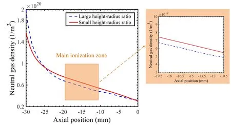
Figure 1.Comparison of neutral gas density distribution on the channel centerline.
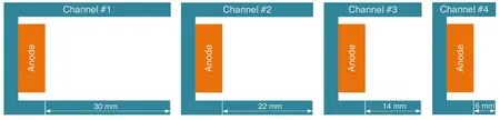
Figure 2.Schematic of four channels of different lengths.
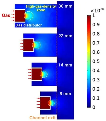
Figure 3.The cloud map of neutral gas density distribution.
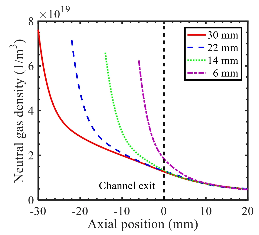
Figure 4.Comparison of neutral gas density distribution on the channel centerline.

Figure 5.Schematic of axial dimensions of four channels.
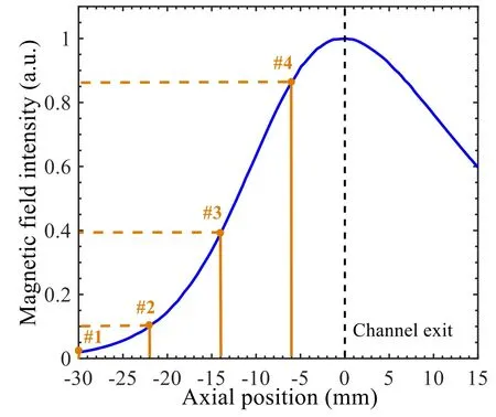
Figure 6.Matching relation between anode position and magnetic field.

Figure 7.Schematic of the calculated domain boundaries.
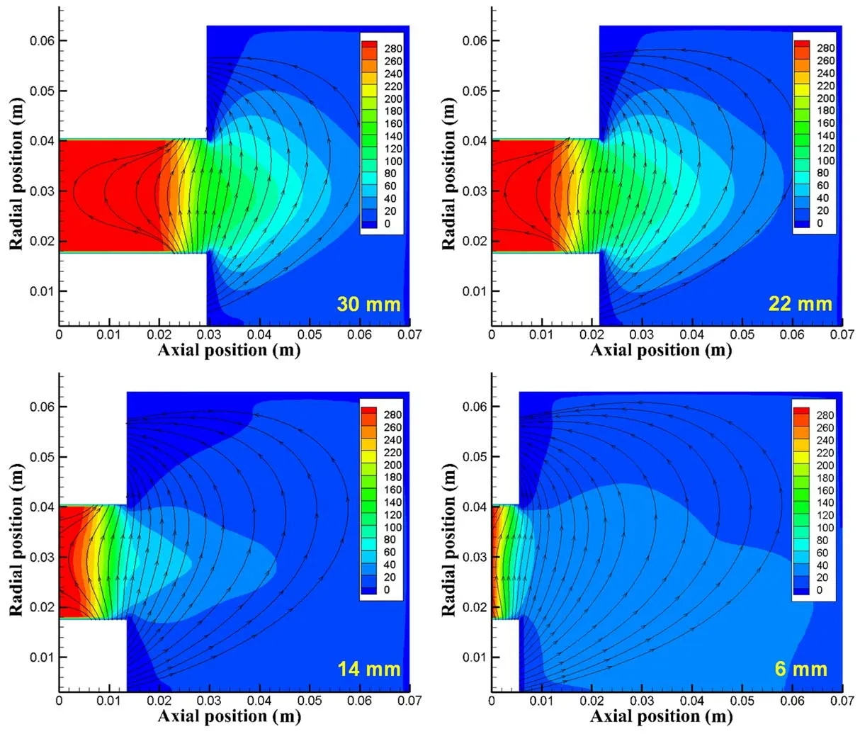
Figure 8.Distribution of magnetic field and electric field.

Figure 9.Axial distribution of ionization rate on the channel centerline.
In order to present the law of gas axial distribution quantitatively,figure 4 shows the comparison of the neutral gas density distribution on the channel centerline.In the process of outward diffusion,the gas density decreases continuously and the decreasing rate slows down gradually.The same law is presented under the four channels.With the shortening of the channel,the neutral gas density distribution moves outwards as a whole.In the range of 10 mm outside the channel outlet,the shorter channel has the advantage of higher gas density.The expected effect of the high-gas-density zone moving outwards is realized.It should be noted that the peak density of neutral gas decreases gradually with the shortening of the channel.Because the smaller wall area of the shorter channel reduces the gas flow resistance,and then increases the gas diffusion rate,the gas density decreases when the gas supply flow rate remains constant.
3.Discharge characteristics and mechanism
3.1.PIC simulation model
In this study,the discharge process of Hall thruster was studied by Particle-in-Cell(PIC)numerical model.It takes propellant atoms,ions and electrons as discrete individual particles,uses the PIC numerical method to solve the particle motion and field distribution,and presents the discharge characteristics of thruster through numerical calculation[18].PIC method cannot only represent the motion,collision,ionization and other physical processes of plasma in the calculation domain,but also obtain the thrust,specific impulse,efficiency and other performance parameters,which is one of the most widely used means to simulate the plasma thruster discharge[19-21].
The PIC simulation adopted the same four channels as mentioned in section 2.1,with lengths of 30 mm,22 mm,14 mm and 6 mm respectively,as shown in figure 5.Under the condition that the position matching between the magnetic field and the channel outlet remains unchanged,the magnetic field intensity corresponding to each anode surface is 3%,10%,39% and 86% of the peak magnetic field intensity,respectively,as shown in figure 6.The discharge voltage was set at 300 V and the anode flow rate was 50 sccm.The magnetic field parameters were obtained by using the twodimensional magnetic field simulation software named finite element method magnetics,and input into the simulation model.
Because of the axisymmetric characteristic of Hall thrusters,the discharge parameters can be considered to be uniform in the circumferential direction,so only the axial(Z)and radial(R)variations of the discharge parameters are considered.For the particle motion process,not only the axial and radial velocities of the particle,but also the circumferential velocities of the particle should be considered.Therefore,the PIC model is a 2D3V model built on the(Z,R)plane.To achieve higher calculation accuracy,the cell size in the domain is 0.5 times smaller than the local Debye length.The time-step interval Δt=0.1ωpe,whereωperepresents the electron oscillation frequency.In order to save the calculation time,Szabo’s simplified model[22]is adopted to increase the heavy particles velocity by reducing the heavy particles mass(to 1/625)and increasing the vacuum permittivity(to 144 times).The average number of each species of particles in each cell is more than 25,which is validated to have little influence on the result.
The calculated domain boundary setting of the model is shown in figure 7.The calculation domain consists of discharge chamber and near-field plume region.The left boundary of the calculated domain in the channel is the gas distributor and anode boundary.The propellant gas enters the channel from this boundary.The anode boundary is the conductor boundary,and the potential on the anode is given manually according to discharge voltage.When the particles collide with the anode boundary,it is considered that the electrons enter the external circuit and disappear.The ions are recombined into atoms by electrons,and then emitted with half the energy of the original ion.The atoms inherit the temperature of the anode surface,and then re-emit from the anode surface.All particles emitted from the anode surface obey a half Maxwell distribution.The upper and lower boundaries of the calculation domain in the channel are the boron nitride(BN)ceramic wall surface boundaries.After colliding with the wall surface,the atoms inherit the wall temperature and then emit evenly into the hemispherical space in a half Maxwell distribution[23].For the collisions of electrons with the wall surface,the secondary electron emission(SEE)effect is considered.On the basis of Morozov model,the improved SEE model and the wall sheath model were adopted[24].The left two boundaries outside the channel are the metal conductor boundaries(the capacitance value is given,and the potential is calculated by the capacitance formula).The upper and right boundaries outside the channel are free boundaries through which the particles disappear.The statistics of the flux and momentum of the ions disappearing through the free boundary can be used to obtain performance parameters such as ion current,thrust and propellant utilization efficiency[25].The lower boundary outside the channel(i.e.the axis of the thruster)is a symmetrical boundary through which the particles will be reflected back to the simulation domain.
In the calculation,uncharged atoms are unaffected by the electric and magnetic fields.Because the electrons are magnetized,the influence of both the electric and magnetic fields on their motion should be considered at the same time.In contrast,the ions are not magnetized;hence,only the force due to the electric field is considered.The motion of the charged particles is solved by the leap-frog scheme with second-order precision[26].The elastic,excitation,and single ionization collisions between electrons and atoms are considered in the model.The data of collision cross sections are taken from Szabo’s PhD thesis[22].Furthermore,the model considers Bohm anomalous conduction and uses a semiempirical coefficient to obtain the Bohm collision frequency[27].Multiple ionization,Coulomb collision and charge exchange collision are not considered in this model.
3.2.Simulation results and analysis
All the PIC results in this study are steady-state time-averaged results within 100 μs after the program runs for approximately 30 h and reaches a steady-state.As the simulated discharge environment is absolute vacuum and the background pressure is 0 Pa,the discharge performance parameters are usually slightly lower than the experimental value,as shown in table 1.The similar influence of backgroundpressure on the performance of the Hall thruster was described in detail in reference[28].Moreover,the previous study has verified that the simulation results based on this simulation program corresponded well with the experiments,especially for the Hall thruster with rated power of 1.35 kW[27].
Table 1 also shows the comparison of the discharge performance parameters of the thruster with different channel lengths under the rated condition.It can be seen that with the shortening of channel length,the performance tends to increase first and then decrease.When the channel length is 22 mm,that is,the magnetic field intensity of anode surface is 10% of the peak magnetic field intensity,the thruster has the highest comprehensive performance,with the anode efficiency up to 55.7%,and the propellant utilization efficiency is significantly higher than that of other calculation examples.When the channel length is reduced to 6 mm,the anode efficiency of the thruster suddenly drops to 23%,and the thrust is also greatly reduced.This phenomenon is worth paying attention to.
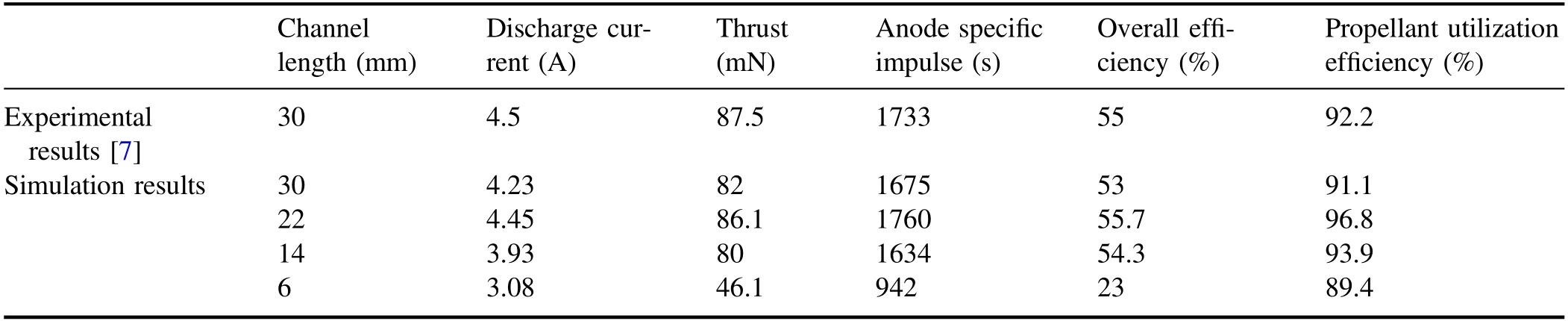
Table 1.Discharge performance parameters of the thruster with different channel lengths.
To clarify the internal mechanism of the influence of channel length on macroscopic performance,the ionization and acceleration processes were further explored.According to the magnetic field and electric field distribution diagram shown in figure 8,it can be seen that an appropriate axial coupling electric field is formed in each discharge channel,which means that stable discharge is achieved in each simulation example.As the channel is gradually shortened,the axial dimension of the high potential zone decreases significantly.However,under the same radial magnetic field,the main potential drop positions of each channel are almost the same,which are located inside the channel near the channel outlet.
The above results have confirmed that the high-gasdensity zone can be moved outward by shortening the channel.Whether this method can play a substantial role in optimizing the ionization process or not remains to be further verified.Figure 9 shows the axial distribution of ionization rate on the channel centerline.In the process of the channel gradually shortening from 30 to 14 mm,the peak ionization rate increases significantly,with a total increase of 62.5%.When the channel is further shortened to 6 mm,the peak ionization rate starts to decrease,but it is still higher than that of two longer channels.It can be seen that appropriately shortening the channel length to optimize the matching of gas flow field and magnetic field can effectively improve the peak ionization rate.It should be noted that with the shortening of the channel,the broadening of the ionization rate distribution gradually decreases,thus reducing the total ionization rate to a certain extent,which is the fundamental reason why the propellant utilization efficiency of 14 mm channel is lower than that of 22 mm channel.
In addition,with the shortening of the channel from 30 to 6 mm,the ionization zone gradually moves towards the channel outlet,which will help to reduce the ion loss on the wall surface,and more concentrated ionization(smaller broadening)can also optimize the acceleration process.Figure 10 shows the ion power loss on the inner and outer walls,which is proportional to the ion flux and ion energy.It can be clearly found that short channels can indeed significantly reduce the ion power loss on the walls,and the 6 mm channel even reaches almost zero loss on the outer wall.This indicates that in addition to the outward movement of the magnetic field[13,29],the outward movement of the anode(shortened channel length)also contributes to discharge without ion loss on the wall surface.
According to the above analysis,the total ionization rate and ion loss the wall surface of the 6 mm channel are relatively lower,and the propellant utilization efficiency can still reach more than 89%.However,its thrust and anode efficiency are only 46.1%and 23%,far less than other channels.Besides the number of ions,ion velocity is also a key factor to determine the thrust.The radial distribution of ion axial velocity at 30 mm outside the channel outlet is shown in figure 11.With the shortening of the channel,the ion axial velocity decreases gradually.When the channel is shortened to 14 and 6 mm,the ion axial velocity decreases significantly,and the peak value maximum decreases by 42.1%.This is the main reason for the sharp decrease of thrust when the channel is excessive short.
The ion axial velocity depends on the energy obtained by the ion during the acceleration process,which is derived from the effective acceleration voltage.Figure 12 shows the axial distribution of plasma potential,where the solid circle represents the position corresponding to the peak ionization rate.With the shortening of the channel,the main ionization zone gradually moves outward,and the plasma potential in the main ionization zone gradually decreases,which makes the ion effective acceleration voltage decrease.This is the main reason for the reduction of the ion axial velocity.As the ionization zone is more concentrated and the acceleration zone is shorter(as shown in figure 9),the ion current density distributions of the Hall thruster with shorter channels are less broad,as shown in figure 13.The corresponding plume divergence angle is small,which is helpful to improve thrust to some extent.However,this positive effect is far less than the negative effect of greatly reducing the voltage utilization efficiency,so the discharge performance of the Hall thrusters with 6 mm channel length is still poor.
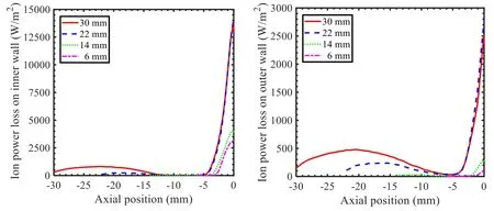
Figure 10.Ion power loss on the wall surfaces.
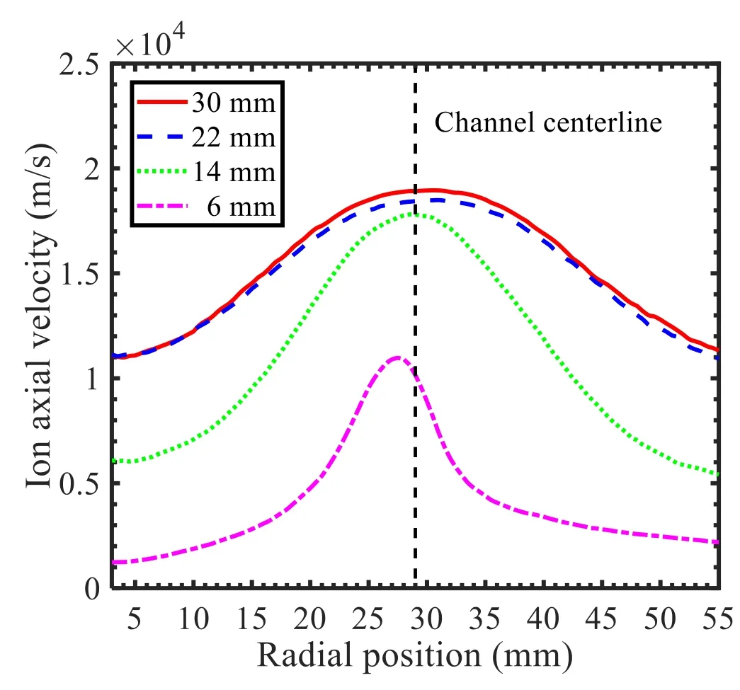
Figure 11.Radial distribution of ion axial velocity at 30 mm outside the channel outlet.
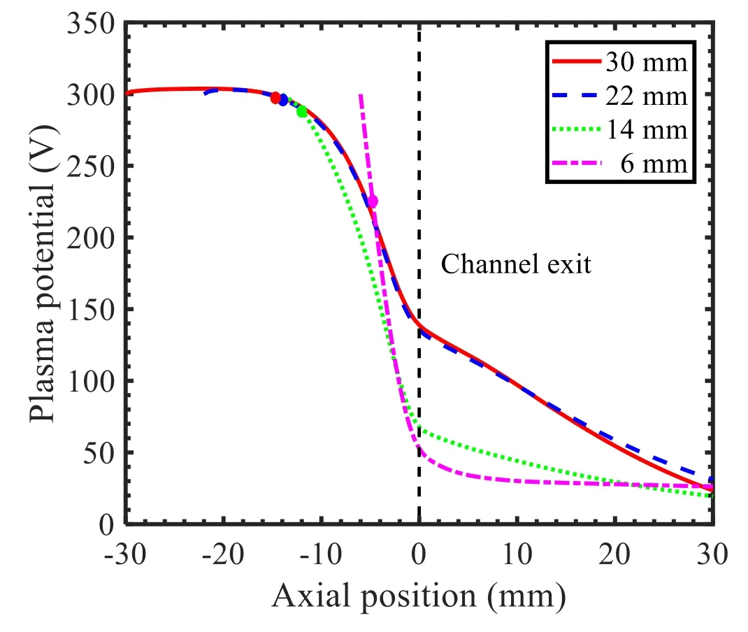
Figure 12.Axial distribution of plasma potential on the channel centerline.
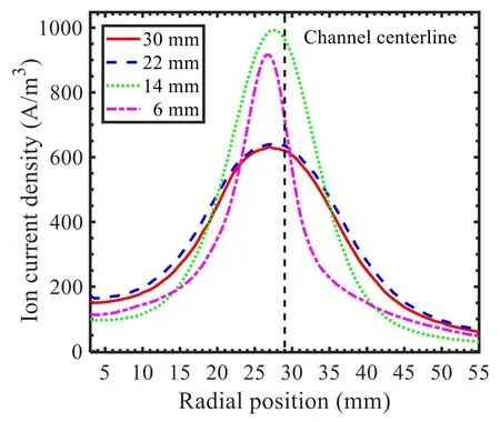
Figure 13.Radial distribution of ion current density at 30 mm outside the channel outlet.
In addition,the shortening of the channel will allow more magnetic flux lines to directly pass through the anode surface(as shown in figure 5),so the electrons will reach the anode more easily under the guidance of these magnetic flux lines.This will affect the ionization effect of neutral gas and the discharge stability of the thruster.Meanwhile,it can be seen from figure 9 that the shorter the channel,the higher the ionization rate at the anode surface.This means that more ions will bombard the anode surface,increasing the power deposition on the anode,which will lead to overheating or ablation of the anode,threatening the discharge stability and service life of the thruster.In the discharge test of HEP-100X with the same power level[30],there was a phenomenon of anode ablation caused by the anode surface being excessively close to the ionization zone.Therefore,not only discharge performance but also discharge reliability should be considered when selecting the optimal channel length.
4.Conclusions
To further optimize the discharge performance of the Hall thruster with large height-radius ratio,the simulations of neutral gas distribution and discharge characteristics were carried out under the variable channel length.The results show that shortening the channel length is helpful to the highgas-density zone to the outward,and then the matching of the gas flow field and magnetic field can be optimized,hence the ionization rate can be improved.Furthermore,the ionization zone moving outward can effectively reduce the ion loss on the wall surface,further improve the propellant utilization efficiency,and show the potential advantage of long-life discharge.However,the excessively short discharge channel will lead to a significant decrease in voltage utilization efficiency and serious loss of thrust and specific impulse.Meanwhile,the anode is excessively close to the ionization zone so that it will carry more power deposition,and the discharge stability and reliability of the thruster are greatly threatened.When the channel length is shortened to 22 mm,that is,the anode surface is located in the axial position corresponding to 10%of the peak magnetic field intensity,the thruster has the best comprehensive discharge performance,and its discharge reliability can be guaranteed.It should be noted that due to differences of channel dimensions,anode structures and magnetic field configurations,the optimal position matching between anode and magnetic field may be different in other Hall thrusters with large height-radius ratios.
Acknowledgments
This work is funded by the Defense Industrial Technology Development Program(No.JCKY2019603B005),National Natural Science Foundation of China(Nos.52076054,51777045)and the Hunan Science and Technology Innovation Project(No.2019RS1102).
猜你喜欢
杂志排行

Plasma Science and Technology的其它文章
- Multi-layer structure formation of relativistic electron beams in plasmas
- Mode structure symmetry breaking of reversed shear Alfvén eigenmodes and its impact on the generation of parallel velocity asymmetries in energetic particle distribution
- Interaction between energetic-ions and internal kink modes in a weak shear tokamak plasma
- Investigation of the compact torus plasma motion in the KTX-CTI device based on circuit analyses
- Anomalous transport driven by ion temperature gradient instability in an anisotropic deuterium-tritium plasma
- Nonlinear excitation of a geodesic acoustic mode by reversed shear Alfvén eignemodes