Experimental Study on the Influencing Factors of Motion Responses on an Air-Floating Caisson with Multiple Compartments
2022-02-28LIUXianqingZHANGPuyangZHAOMingjieDINGHongyanLEConghuanLVNanandLUOSheng
LIU Xianqing ,ZHANG Puyang ,ZHAO Mingjie ,DING HongyanLE ConghuanLV Nan,and LUO Sheng
1) State Key Laboratory of Hydraulic Engineering Simulation and Safety,Tianjin University,Tianjin 300072,China
2) National Engineering Research Center for Inland Waterway Regulation,Chongqing Jiaotong University,Chongqing 400074, China
3) Department of Military Facilities, Army Logistics University of PLA,Chongqing 401331, China
Abstract The structure of an air-floating caisson is suitable for the major structure of caisson-type artificial islands.Thus,it has been rapidly developed and widely used in the exploration and development of oil and gas fields in shallow sea and intertidal zones.Air-floating transportation technology is one of the key technologies employed in this structure.In this paper,the factors influencing the dynamic response characteristics of air-floating caisson with multi-compartments (AFCMC) were studied using model tests.The length and the height of each air-floating structure in the model were 1.0 and 0.1 m,respectively.In addition,the 1:100 models with 6,8,and 10 compartments under regular waves were tested in the wave flume,respectively.In the experiments,the respective water depths were set at 0.2,0.3,and 0.4 m,and the corresponding drafts were 0.05,0.06,and 0.07 m.Results show that with the increase of draft,the heave natural period increased and the maximum amplitude of the heave motion decreased.Meanwhile,the pitch motion decreased at 6 and 8 compartments and increased at 10 compartments.As the water depth increased,the maximum amplitude and amplitude change of heave and pitch motions first increased and then decreased.However,several amplitudes close to the maximum amplitude appeared in the measured period at shallower water depth,thereby indicating the vertical movements of the structure enhanced under shallow water.The increase in the number of compartments reduced the vertical movements under 6.0 m draft,but it increased the vertical movements under 5.0 and 7.0 m draft.Thus,increasing the number of compartments has a limited capacity to improve the motion performance of the structure.
Key words air-floating caisson structure;response amplitude operator (RAO);draft;water depth;compartment
1 Introduction
Conventional marine structures,whether ships or floating platforms,are marine-floating structures with bottom parts supported on the water surface by the buoyancy of water (Bhattachyya,1978;Wilson,1986).With the advancement of marine development and the improvement of marine technology,new structural forms have been introduced.Among these,the air-floating structure is one of the structural forms that have been widely used in recent years.Unlike the conventional floating body,this structure is bottomless and is supported on the water surface by means of air cushion inside the structure (Seidl,1980;Bieet al.,2002).The main geometric shapes of air-floating structures applied in practices are cylindrical-and boxtype structures.On the one hand,the cylindrical-type structure is mainly used as suction anchor for mooring,bucket foundation for jacket,wind turbine,and as breakwater foundation (Senpere and Auvergne,1982;Tjeita,1995;Byrneet al.,2002;Heet al.,2012).On the other hand,the box-type structure is used for the major structure of very large floating structures (VLFS),such as artificial islands,as well as mobile offshore base and floating airports,to name a few (Pinkster and Fauzi,1997;Guret and Hermans,2001;Ikomaet al.,2006;Dinget al.,2016).
Due to the bottom opening and the compressibility of the air cushion inside the structure,the dynamic characteristics and motion responses of an air-floating structure under the action of ocean environment are different from those of a conventional floating body.Iwata (1986) analyzed the air-floating box-type structure partially supported by an air cushion in waves using eigen-function expansion and matching method and verified the theory through experiments.The results of that study revealed that with the initial air pressure increase,the draft decrease and the roll period increase;hence,the natural period of the structure can be easily changed by adjusting the air volume in the air cushion to change the initial pressure.Subsequently,Iwata (1987) studied the motion and deformation characteristics of the structure moored by catenaries and accurately predicted the internal pressure change and the tension of the mooring line.A three-dimensional (3D) calculation method to determine the air cushion-supported floating body was proposed by scientists from Delft University of Technology.The wave forces,hydrodynamic coefficients,and internal air pressure of the structure supported by structures with one and two air cushions were verified by model tests (Pinksteret al.,1998).Van Kessel and Pinkster(2007a,2007b) and Van Kessel (2010) verified that the existence of air cushion significantly affects the stability and motion response,as well as reduces the ship bending moment of the structure.Cheunget al.(2000)used a boundary integral equation to model the dynamic response of a pneumatic floating platform and introduced the air-pocket factor proposed by Seidl to consider the effect of air cushion.The numerical simulation results were verified by model tests.Their results show that the dynamic response of the pneumatic platform can be quite sensitive to the air-pocket factor over a range of wave periods (Cheunget al.,2000).
The air and water columns also act as cushions in reducing the hydrodynamic load on the structure.Lee and Newman (2000) used the higher-order panel program HIPAN and model tests to study the motion responses of VLFS in waves with a characteristic length to wavelength ratio that is greater than 10.The elevation of the interface is represented by an appropriate set of Fourier generalized modes with unknown amplitudes.In another work,Lee and Newman (2016) extended the conventional boundary integral equation for the solutions of linear wave-body interactions to include the radiation solutions due to the oscillatory pressures applied on the free surface.
Researchers from the University of Western Australia systematically studied the hydrostatic and motion response characteristics of air cushion-supported structures with multiple compartments.Chenuet al.(2004) determined the effects of the air cushion on the metacentric height and,coupled with the water depth,on the added mass and natural frequency in heave and pitch.Their experimental results showed that compartmentalizing the air cushion and varying the water depth affected the hydrodynamic characteristics of the floating structure.Thiagarajan (2009)presented theoretical formulations to evaluate the restoring moment of structures supported by air cushions at zero forward speed.Further,a correction factor for the metacentric height incorporating the air cushion effects is proposed.In addition,Thiagarajanet al.(2004) and Thiagarajan and Morris-Thomas (2006) studied the heave and pitch motions of the air-floating structure by means of model tests and long wavelength theory.Their results revealed that introducing air cushion to support concrete gravity structure increases the pitch response while having little effect on the heave motion.
Research on the stability and seakeeping of air-floating structures not only requires theoretical analyses and model tests,but also needs data of actual construction and operation during air-floating transportation.Although the influences of internal and external factors on the air-floating structures were analyzed in the above mentioned studies,research on the motion characteristics of AFCMC is far from enough.Thus,in the current paper,the response characteristics of the heave and pitch motions of AFCMC were measured and discussed by model tests in a wave flume.First,to determine the influence of draft on the motion responses during air-floating transportation,the model tests with different drafts for each AFCMC were performed under the same water depth.Second,model tests under different water depths were conducted under the same draft to determine the motion response characteristics of the structure from shallow water to deep water or from deep water to shallow water during transportation.Third,the model tests with 6,8,and 10 compartments were performed under certain water depths and drafts to study the influence of compartments on the motion characteristics.
2 Experimental Campaigns
2.1 Physical Model
Three prototypes with 6,8,and 10 compartments were designed to study the motion response characteristics of AFCMC.The three prototypes are shown in Figs.1–3,respectively.
The geometric dimensions of the prototypes were as follows:length of 100 m,width of 30 m,and height of 10 m.The thickness of the outer wall and the top lid was 0.2 m,and the wall thickness of the compartments was 0.1 m.All the models were made of stainless steel.The similarity ratio between the model and the prototype meeting the geometric similarity and Froude similarity is 1:100.The size of the models was as follows:1.0 m in length,0.3 m in width,and 0.1 m in height.Fig.4 shows the models corresponding to Prototypes 1–3,with the mass of 9.734,10.205,and 10.676 kg,respectively.The detailed geometric parameters of Prototypes 1–3 and Models 1–3 are shown in Table 1.To adjust the draft,exhaust valves were set on the top plate of each compartment to pump air in or out the structure.

Fig.1 Prototype 1 with six compartments.

Fig.2 Prototype 2 with eight compartments.

Fig.3 Prototype 3 with ten compartments.

Fig.4 Models in water.

Table 1 Detailed geometric parameters of prototypes and models
2.2 Experiment Setup
The experiment was conducted in the wave flume of the Logistics Engineering University.The geometry of the flume is as follows:30 m in length,1.0 m in width,and 2.0 m in height.A schematic of the experimental setup is shown in Fig.5.Regular waves are generated by pistonwave maker at one end of the flume,and a wave damper is installed on the other side to eliminate wave energy and prevent reflected waves from interfering with the accuracy of the test.

Fig.5 Schematic of the experimental setup.
The model was arranged at the position of 12.0 m away from the wave maker,and a Cartesian coordinate system was established at the center of the structure on the still water surface.Thexaxis was parallel to the propagation direction of the incident wave,theyaxis was parallel to the direction of the plate of wave maker,and thezaxis was vertical upward.During the test,the wave height was measured by a wave probe located between the structure and the wave maker,and the model data were obtained by a CS-VG-02A vertical gyroscope arranged at the top center of the structure.As mentioned in Section 2.1,the similarity scale for models to the prototypes of AFCMC was based on geometric similarity and gravity similarity.The similarity ratio of translational accelerations in the surge,sway,and heave motions,as well as the rotational angles in the roll,pitch,and yaw motions were all set at 1:1.The maximum amplitudes of heave acceleration (Mh) and pitch rotation (Mp) of AFCMC were obtained from the test data,and the wave amplitudes (Hi) for each period were obtained by the wave height sensor records.The heave and pitch RAOs were defined asMh/HiandMp/Hi,respectively.All the graphs for RAOs are shown in prototype scale.
2.3 Regular Wave Tests
Regular wave tests in a certain range of periods at the same wave height were required to determine the amplitude frequency response characteristics of the heave and pitch motion.Given that the similarity scale of the experiment was 1:100,the similarity ratios of the wave height and wave period were set at 1:100 and 1:10,respectively.In the test,the wave height was 0.02 m,and the wave frequency range was 0.5– 1.5 s.Then,the corresponding water depths were set at 0.2,0.3,and 0.4 m,and the drafts were set to 0.05,0.06,and 0.07 m to study the influences of water depth and draft on the motion responses.Data were obtained at 200 Hz and post-processed using Fourier analysis to recover the amplitude information.
3 Results and Discussion
3.1 Effects of Drafts
The RAOs for the heave acceleration of Model 1 at a water depth of 20 m with different drafts are shown in Fig.6(a).As can be seen,the maximum amplitudes of the heave acceleration of 0.091,0.096,and 0.08 m s-2occur at about 7,9,and 9 s at drafts of 5.0,6.0.and 7.0 m,respectively.This means that,with the increase of draft,the natural period for heave motion increases,while the heave motion responses first increase and then decrease.With the increase of draft,the heave acceleration decreases when the wave period is less than 9 s;however,when the wave period is greater than 9 s,the heave acceleration decreases first and then increases.
The RAOs for the pitch angle of Model 1 at a water depth of 20 m with different drafts are shown in Fig.6(b).As can be seen,the maximum amplitudes of pitch angle 1.62˚,2.43˚,and 2.26˚ appear near 9,10,and 10 s at drafts of 5.0,6.0,and 7.0 m,respectively.Hence,with the increase of draft,the natural period of the pitch motion increases,and the pitch motion response first increases and then decreases.In addition,the pitch response at 7.0 m draft is the smallest in most periods.

Fig.6 RAOs for Model 1 with different drafts.
The RAOs for the heave acceleration of Model 2 at a water depth of 20 m with different drafts are shown in Fig.7(a).The figure shows that the maximum amplitudes of heave acceleration at drafts of 5.0,6.0,and 7.0 m are 0.091,0.080,and 0.066 m s-2,when the wave periods are 6,9,and 9 s,respectively.These values indicate that,as the draft increases,the heave natural period increases,while the heave response shows a downward trend.The change trend of the period less than 9 s is obviously greater than that of the period greater than 9 s.The heave response at 7.0 m draft is the smallest in most periods.
The RAOs for pitch angles of Model 2 at a water depth of 20 m with different drafts are shown in Fig.7(b).The figure shows that the maximum amplitude of the pitch angle appears at about 10– 11 s.Furthermore,the maximum amplitudes of the pitch angles are 1.95˚,1.92˚,and 1.87˚ at drafts of 5.0,6.0,and 7.0 m,respectively.These values show that the pitch response decreases with the increase of draft.In addition,the pitch amplitudes are stable at 1.0˚ in the larger periods,whereas the pitch response at 7.0 m draft is the minimum in most periods.
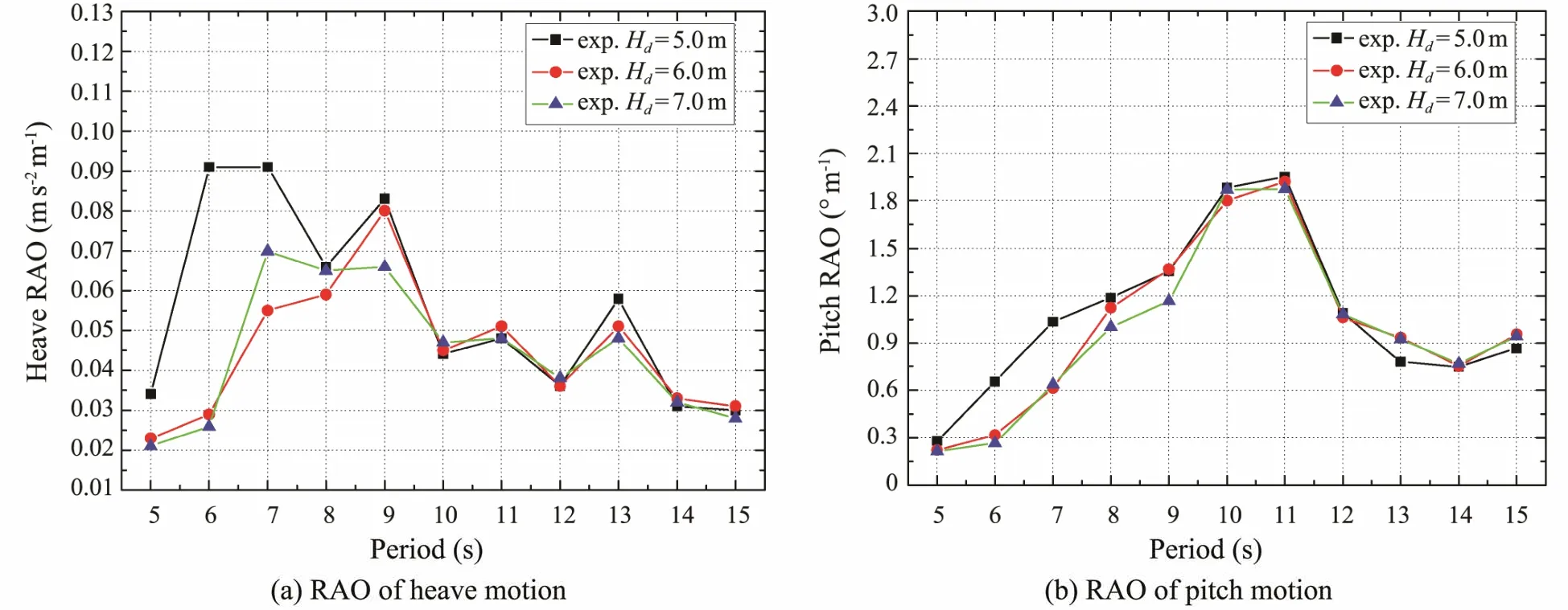
Fig.7 RAOs for Model 2 with different drafts.
The RAOs for the heave acceleration of Model 3 at a water depth of 20 m with different drafts are shown in Fig.8(a).The corresponding maximum amplitudes of the heave acceleration at drafts of 5.0,6.0,and 7.0 m are 0.103,0.076,and 0.081 m s-2,which appear in the vicinities of wave periods of 6,9,and 11 s,respectively.These results reveal that,with the increase of draft,the natural period of heave motion increases,while the motion response decreases first and then increases slightly.Special attention should be paid to the fact that the heave amplitudes at 9 and 11 s are close to the maximum amplitude.The heave response is the smallest in most periods at a draft of 7.0 m.

Fig.8 RAOs for Model 3 with different drafts.
The RAOs for the pitch angle of Model 3 at a water depth of 20 m with different drafts are shown in Fig.8(b).The maximum amplitudes of pitch angle still appear at about 10 s,and the amplitude changes in the period range of 8– 11 s are obviously greater than that of other periods.The pitch amplitudes are also stable at 1.0˚ in the larger periods.
3.2 Effects of Water Depth
The RAOs for the heave acceleration of Model 1 at different water depths with a 6.0 m draft are shown in Fig.9(a).As can be seen,the maximum (0.096 m s-2) and minimum(0.026 m s-2) amplitudes of the heave acceleration at a water depth of 20 m appear at 9 and 15 s,respectively.In addition,the maximum (0.097 m s-2) and minimum (0.035 m s-2) values at a water depth of 30 appear at 9 and 15 s,respectively.Finally,the maximum (0.071 m s-2) and minimum (0.032 m s-2) values at a water depth of 40 m appear at 14 and 6 s,respectively.These results indicate that,as the water depth increases,the maximum amplitude and amplitude change show a decreasing trend.The reason is that the structure moves from deep water to shallow water,the wavelength becomes shorter,the wave speed becomes slower,and the gap between the bottom part and the seabed becomes smaller.The blockage effect results in the sinking of the center of gravity.In turn,this causes the draft to increase by an increment,resulting in drastic changes in the heave motion.
The RAOs for the pitch angle of Model 1 at different water depths with a 6.0 m draft are shown in Fig.9(b).The maximum (2.43˚) and minimum (0.36˚) amplitudes of the pitch angle appear at 10 and 6 s,respectively,at a water depth of 20 m.The maximum (2.56˚) and minimum (0.25˚)values occur at 12 and 5 s,respectively,at a water depth of 30 m.Finally,the maximum (1.73˚) and minimum values (0.40˚) at a water depth of 40 m appear at 9 and 5 s,respectively.These values indicate that,as the water depth increases,the amplitude and amplitude change for pitch motion first increase and then decrease.The amplitude change of the pitch angle at a water depth of 40 m is much smaller than that of other water depths.Due to the shallow water effect,the distance between the structure and the seabed decreases with the decrease of the water depth,thus resulting in higher relative velocity and lower bottom pressure.Furthermore,the pressure changes between the fore and aft of the structure cause additional rocking motion.

Fig.9 RAOs for Model 1 with different water depths.
The RAOs for the heave acceleration of Model 2 at different water depths with a 6.0 m draft are shown in Fig.10(a).As shown in the figure,the maximum (0.080 m s-2)and minimum (0.023 m s-2) amplitudes of the heave acceleration at a water depth of 20 m appear at 9 and 5 s,respectively.The maximum (0.101 m s-2) and minimum(0.031 m s-2) values occur at 7 and 5 s at a water depth of 30 m,respectively.Finally,the maximum (0.089 m s-2) and minimum (0.030 m s-2) values at a water depth of 40 m occur at 7 and 15 s,respectively.These values show that,as the water depth increases,the amplitude and amplitude changes of the heave acceleration show a trend of increasing first and then decreasing.The amplitude change of the pitch angle at a water depth of 20 m is much smaller than that of other water depths.The reason is that the motion of the AFCMC is similar to the traditional floating body due to the increasing number of compartments;thus,the restraining effect of the air cushion on the motion is reduced to enhance the heave motion.
The RAOs for the pitch angle of Model 2 at different water depths with a draft of 6.0 m are shown in Fig.10(b).The maximum (1.92˚) and minimum (0.22˚) amplitudes of the pitch angle at a water depth of 20 m appear at 10 and 6 s,respectively.In addition,the maximum (2.38˚) and minimum (0.29˚) values at a water depth of 30 m occur at 12 and 5 s,respectively.Finally,the maximum (1.42˚) and minimum (0.30˚) values at a water depth of 40 m occur at 9 and 5 s,respectively.As in Model 1,the amplitude and amplitude change presented a trend of first increasing and then decreasing with the increase of water depth.Furthermore,the amplitude change of the pitch angle at water depth of 40 m is much smaller than that of other water depths.

Fig.10 RAOs for Model 2 with different water depths.
The RAOs for the heave acceleration of Model 3 at different water depths with a draft of 6.0 m are shown in Fig.11(a).As can be seen in the figure,the maximum(0.076 m s-2) and minimum (0.034 m s-2) amplitudes of the heave acceleration at a water depth of 20 m appear at 9 and 5 s,respectively.In addition,the maximum (0.099 m s-2) and minimum (0.037 m s-2) values at a water depth of 30 m occur at 9 and 7 s,respectively.Finally,the maximum (0.099 m s-2) and minimum (0.028 m s-2) at a water depth of 40 m occur at 7 and 5 s,respectively.These results indicate that the amplitude and change of amplitude of the heave acceleration increase with the increase of water depth.As in Model 2,the amplitude and amplitude changes of the heave acceleration at 20 m depth are less than those of other water depths.
The RAOs for the pitch angle of Model 3 at different water depths with a draft of 6.0 m are shown in Fig.11(b).The maximum (1.99˚) and minimum (0.26˚) amplitudes of the pitch angle at a water depth of 20 m appear at 10 and 6 s,respectively.The maximum (2.40˚) and minimum(0.33˚) values at a water depth of 30 m occur at 12 and 5 s,respectively.Finally,the maximum (1.83˚) and minimum(0.29˚) values at a water depth of 40 m occur at 9 and 5 s,respectively.As in Model 2,the amplitude and amplitude change presented a trend of first increasing and then decreasing with the increase of water depth.Furthermore,the amplitude change of the pitch angle at water depth of 40 m is much smaller than that of other water depths.

Fig.11 RAOs for Model 3 with different water depths.
3.3 Effects of the Number of Compartments
The RAOs for the heave acceleration and pitch angle with different numbers of compartments at a draft of 5.0 m are shown in Fig.12.As shown in Fig.12(a),the period for the maximum amplitude of heave acceleration is about 7 s.As the number of compartments increases,the maximum amplitude of heave acceleration tends to increase as well.Especially for Model 3,the amplitudes at the period of 9 and 11 s are close to the maximum amplitudes.This is because the motion is similar to the traditional floating body due to the increasing compartments;thus,the restraining effect of the air cushion on the motion is reduced to enhance the heave motion.As shown in Fig.12(b),the maximum amplitudes of the pitch angles for Model 1,Model 2,and Model 3,which are 1.62˚,1.95˚ and 1.88˚,occur at 8,11,and 10 s,respectively.The amplitude and the period of maximum amplitude for Model 1 are less than those of Model 2 and Model 3.The reason is that the moment of inertia increases due to the increasing number of compartments,thus leading to an increase of the natural period.Hence,with the smaller draft,the restraining effect of the air cushion on the motion is reduced to enhance the pitch motion.

Fig.12 RAOs at 5.0 m draft with different compartments.
The RAOs for the heave acceleration and pitch angle with different numbers of compartments at a draft of 6.0 m are shown in Fig.13.The periods for the maximum amplitude of heave acceleration are all about 9 s.With the increase in the number of compartments,the maximum amplitude of heave acceleration tends to increase.When the period is less than 9 s,the amplitude of Model 2 is the smallest,whereas when the period is longer than 9 s,the amplitude of Model 3 is the smallest.As shown in Fig.13(b),the maximum amplitudes of the pitch angle for Model 1,Model 2,and Model 3,which are 2.43˚,1.92˚,and 1.99˚,occur at 10,11,and 10 s,respectively.As the number of compartments increases,the maximum amplitude of the heave acceleration tends to decrease first and then increase slightly.In most periods,the amplitude of the pitch angle of Model 2 is obviously smaller than those of Model 1 and Model 3.Comparing Figs.12(a) and 12(b),it can be observed that improving the rocking performance of AFCMC by only increasing the number of compartments has a limited effect.However,the increase in the number of compartment causes an increase in the amount of connecting materials and additional costs,which does not meet the requirements of low-cost for air-floating structure.
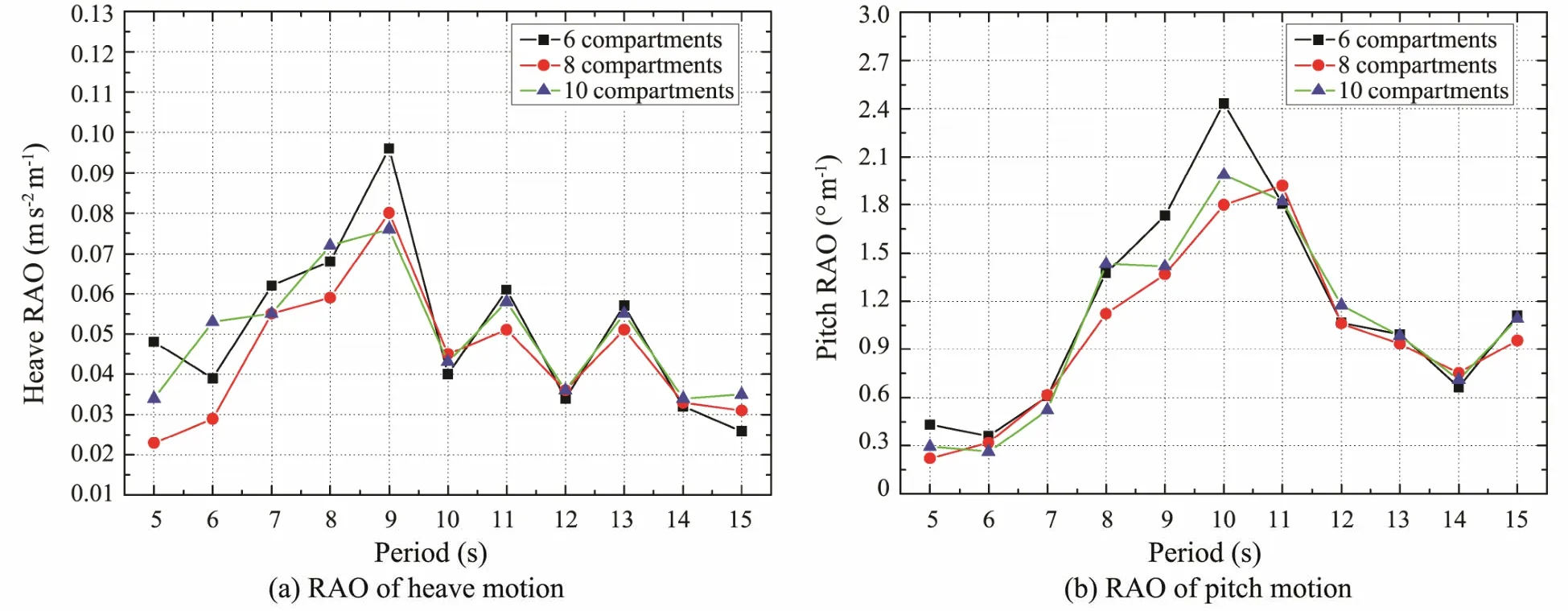
Fig.13 RAOs at 6.0 m draft with different compartments.
The RAOs for the heave acceleration and pitch angle with different numbers of compartments at a draft of 7.0 m are shown in Fig.14.As shown in Fig.14(a),as the number of compartments increases,the maximum amplitudes of the heave acceleration and pitch angle first decrease and then increase.However,the amplitudes of the oscillating motion for Model 2 and Model 3 are less than those for Model 1 and those of Model 3 is greater than that of Model 1.Therefore,improving the rocking performance of AFCMC by only increasing the number of compartments has a limited effect.Furthermore,enhancing the heave motion with the increase of compartments is detrimental to the transport performance of the entire structure.

Fig.14 RAOs at 7.0 m draft with different compartments.
4 Conclusions
In this paper,the parameters of the heave and pitch motions for AFCMC under regular waves are measured through a series of model tests.The effects of draft,water depth,and number of compartments on the motion response characteristics are studied.The main conclusions are as follows:
1) With the increase of draft,the heave natural period increases while the maximum amplitudes of the heave and pitch motions decrease.However,with a higher number of compartments,the motion of AFCMC becomes similar to the traditional floating body.Furthermore,the restraining effect of the air cushion on the motion is reduced to enhance the pitch motion.
2) As the water depth increases,the maximum amplitude and amplitude change of the heave and pitch motions first increase and then decrease.However,the amplitude of pitch motion in shallower water depth and the amplitude of heave motion in deeper water depth are close to the maximum amplitude.This indicates that the influence of water depth on the oscillating motion of AFCMC is significant.
3) As the number of compartments increases,the vertical motion of AFCMC can be reduced at a draft of 6.0 m,but the heave motions at drafts of 5.0 and 7.0 m are enhanced.The responses for Model 1 at a smaller draft and Model 2 at larger draft are smaller.In particular,improving the motion response characteristics by only increasing the number of compartments can only generate a limited effect.
Acknowledgements
The author would like to acknowledge the support provided by the National Science Foundation of China (No.52171274),the National Key Research and Development Project (No.2018YFC0810402),the Chongqing Elite Innovation and Entrepreneurship Demonstration Team (No.CQYC201903204),the Chongqing Special Post-doctoral Science Foundation (No.XM2019),and the State Key Laboratory of Hydraulic Engineering Simulation and Safety(Tianjin University) (No.HESS-12).
杂志排行

Journal of Ocean University of China的其它文章
- Numerical Simulation and Analysis of Storm Surges Under Different Extreme Weather Event and Typhoon Experiments in the South Yellow Sea
- Analysis of Wave Distributions Using the WAVEWATCH-III Model in the Arctic Ocean
- Multi-Objective Weather Routing Algorithm for Ships Based on Hybrid Particle Swarm Optimization
- Placement Optimization Method of FPSO Gas Detectors Based on Leakage Risk
- Effect of Temperature on the Acoustic Reflection Characteristics of Seafloor Surface Sediments
- Variations of the Eco-Hydro-Climatic Environment Response to the 2015/2016 Super El Niño Event in the Mindanao Dome Upwelling System