Effect of staggered array structure on the flow field of micro gas chromatographic column
2022-01-23DaohanGe葛道晗ZhouHu胡州LiqiangZhang张立强andShiningZhu祝世宁
Daohan Ge(葛道晗) Zhou Hu(胡州) Liqiang Zhang(张立强) and Shining Zhu(祝世宁)
1Institute of Intelligent Flexible Mechatronics,Jiangsu University,Zhenjiang 212013,China
2National Laboratory of Solid State Microstructures,School of Physics,Nanjing University,Nanjing 210093,China
Keywords: micro electromechanical system(MEMS),micro gas chromatography
1. Introduction
With the rapid advancement of industrialization, microsensing detection has also developed rapidly. Compared with the traditional detection instruments, micro-sensors have excellent performance in reducing power consumption and saving costs.[1-3]Micro gas chromatography (GC) is a kind of sensor for gas composition analysis, which is widely used in medical detection, environmental detection and other fields.In the process of responding to emergencies, higher requirements have been put forward for rapid on-site analysis and detection.[4,5]The traditional GC is limited to be used in the laboratory because of its large size,heavy mass and large energy consumption.[6]Therefore,the development of miniature gas chromatographic column is of great significance to the miniaturization of GC system, the realization of outdoor detection and energy conservation and emission reduction.[7]
In recent years, some progress has been made in the research of micro GC column. The micro electromechanical system (MEMS) was used to fabricate the micron scale gas chromatographic column structures on silicon wafers.[8]In the comparative study on the separation performance of semipacked micro GC columns embedded with columns of different cross-sections,it has been proven that a rectangular crosssection posts with a high aspect ratio can achieve higher separation performance.[7,9,10]In order to improve the separation efficiency, some researchers put forward the study of multichannel micro GC column. The experiment proved that the multi-channel micro GC column had a greater improvement in separation efficiency compared with the single-channel column, but also put forward a higher requirement for the pressure provided by carrier gas system.[11]Some researchers have proposed the design of a semi-packed micro GC column,which can improve the separation efficiency while maintain the pressure of the carrier gas system.[12,13]
The semi-packed micro gas chromatographic column was fabricated by MEMS technology on the silicon wafer to produce the micro channel structure and micro posts,and then the silicon wafer was encapsulated by the silicon wafer bonding technology.[8,11]The stationary phase coating with uniform film thickness was formed in the channel by using the stationary phase coating technique.[8]Uniform flow field is the key to uniform coating of stationary phase coating.[14]The optimization of micro-sensing structure has an important effect on the improvement of sensing performance.[15,16]The problems of flow field control and separation performance in stationary phase coating process of chromatographic column can be realized by optimal configuration and reasonable microstructure design.[17,18]Reasonable chromatographic column microstructure design can make the liquid-phase coating material have a good uniform flow rate distribution during the coating process, to form a uniform stationary phase coating.[19]In addition, it can effectively suppress the eddy current diffusion phenomenon generated by the separated gas during the separation process,thereby making the chromatography column have better separation performance.[20,21]In the study of semi-packed micro GC columns, some scholars conducted a comparative study on the effect of micropacked columns with square cross-sectional shape, circular cross-sectional shape and elliptical cross-sectional shape on the separation performance.[22,23]Some researchers also improved the uniformity of the velocity field inside the column by optimizing the position parameters of the micropacked column.[24]In previous studies, a regular rectangular array was generally used for the arrangement of micropacked columns.[25]By simulating the velocity field of a traditional rectangular array semi-packed micro GC column,the results show that there are obvious velocity fluctuations in the channel direction. In order to effectively suppress it, a crosssemi-packed array micro GC column chip design method was proposed in this paper. Based on the finite element method,the semi-packed micro gas chromatography column with staggered array and the traditional rectangular array semi-packed micro GC column were compared and studied.
2. Modeling of microstructure flow field
2.1. Structure design of semi-packed micro GC column
The semi-packed rectangular micro GC column structures used in previous studies all adopt a serpentine channel layout,which has better separation performance compared to the circular spiral layout and square spiral layout.[26]Therefore,the structure of the serpentine channel layout is used in this study.The channel adopts a cross-section channel with a height of 240 µm and a width of 200 µm. The channel is divided into multiple straight channel parts and connected curve parts,with total length of 1 m. The traditional rectangular array of semipacked micro GC columns(CRAC)and the staggered array of semi-packed micro GC columns(CSAC)were provided with three rows of micro-packed columns inside the straight channel(Fig.1). Both CRAC and CSAC use the same layout position parameters. According to previous studies, more uniform velocity distribution between flow channels can be obtained by the non-equidistant arrangement. Therefore, nonequidistant arrangement was also adopted between the three rows of micro-filled columns proposed by us. The spacing between the specific micro-packed column and the channel wall was 30µm,25µm,25µm,and 30µm,respectively.
We will carry out a comparative study of the velocity field distribution and pressure distribution of the micro-packed columns with circular cross-sections in the traditional rectangular array arrangement and the staggered array arrangement.The effects of array spacing and dislocation spacing along the channel direction on the velocity field are discussed separately.

Fig.1.This is a diagram of a semi-packed staggered micro chromatographic column. The light green material is type 100 silicon wafer,the orange material is fixed phase coating material(PDMS),and the light blue material is heat resistant glass sheet(Pyrex). Three rows of micro columns divide the flow into four channels: a,b,c,and d.
For semi-packed micro gas chromatography columns,the array spacing is an important factor affecting the velocity field distribution. In this paper, the effect of different array spacing on the velocity field distribution of CRAC was studied.In the design of five groups of structures, the micro-packed columns are all circular cross-section columns with a diameter of 30µm. Therefore,the effective width of the five groups of structures was 110 µm. The array spacing was set to be 50 µm, 55 µm, 60 µm, 65 µm and 70 µm, respectively, and the dislocation spacing was set to be 0µm.
The staggered semi-packed micro chromatographic column structure presented in this paper is formed by the second row of the provided three rows microarray columns moving backwards or forwards. The effect of CSAC on the velocity field distribution by setting different dislocation spacing was studied. The dislocation spacing was set to be 10µm,20µm,30µm,40µm,and 50µm,respectively,under the same array spacing of the micro-packed columns which was 60µm.
3. Results and discussion
3.1. Effect of velocity field on the performance of GC column
In the separation process of the GC column, the components to be separated will undergo mass transfer between the mobile phase and the stationary phase,as well as the random diffusion caused by the thermal motion of the molecules. Due to the different dissolution and adsorption capacity of different components in the stationary phase,the mixed components can be gradually separated in the flow process of the column.Van Deemter in 1956[27]proposed the velocity theory of chromatographic columns with the purpose to better describe this phenomenon,[27]
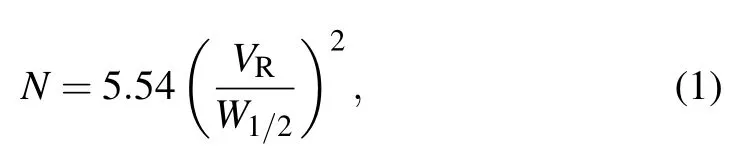
whereW1/2andVRare the half-width and the retention volume, respectively, andNis the number of theoretical plates.This is an important indicator to quantify the separation performance of GC columns.
In the chromatographic separation process, the uniform flow rate distribution has an important impact on the results of chromatographic column separation. The uniformity of the velocity field contributes to the consistency of the longitudinal velocity of the material during the adsorption and desorption during mass transfer,which means that the adsorption and desorption time in the column is equal. This effectively reduces the broadening of the chromatographic peak. From Eq. (1),it can be seen that reducing the peak broadening can obtain a higher number of theoretical plates.
In the mass transfer process of the separated components in the mobile phase and the stationary phase, the mass transfer resistance is an important part that affects the heightequivalent-to-a-theoretical plate(HETP).[28]The equation for the transmission resistance in the stationary phase is as follows:
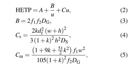
whereAis the eddy diffusion term,Bis the molecular diffusion term, andCis the mass transfer resistance term. It has been known from previous studies that the effects of eddy diffusion terms are negligible for semi packed micro GC columns.Bis mainly related to the irregular motion caused by thermal motion of molecules. Mass transfer resistance coefficientCis divided into stationary phase transfer resistance(Cs)and mobile phase transfer resistance(Cm).dfis the film thickness of the stationary phase.wandhare the width and height of the rectangular channel,DGandDSare the diffusion coefficients of solute in carrier gas and fixed phase, respectively,f1andf2are the correction coefficients of gas compression. Stationary phase coating is an important part of column preparation.Whether using static coating technology or dynamic coating technology,the stationary phase solution needs to be pumped into the chromatographic column. In this link, the velocity distribution affects the residence time of the stationary phase solution at each position in the column. Therefore, uneven flow velocity will cause uneven film thickness of the stationary phase.Whendfis not uniform,the mass transfer resistance is different. This causes to additional band broadening of the chromatographic peak.Cmis only related to the channel width(w),mass transfer coefficientDG,retention factorkand correction coefficients of gas compression.In conclusion,in order to obtain superior separation performance, the velocity between the four runner segments of semi-packed column should be as consistent as possible.
3.2. Effect of array spacing on flow field distribution
In order to explore the influence of the array spacing on the semi-filled micro gas phase column,the flow field analysis module of COMSOL multiphysics software was used. Under the conditions of setting the same inlet velocity,ambient temperature and gas parameters,the steady-state flow field distribution of five semi-filled micro gas phase columns including CRAC1, CRAC2, CRAC3, CRAC4, and CRAC5 were analyzed(Fig.2).
It can be drawn from Figs.2(a)-2(e)that the three rows of micro-packed columns of CRAC1,CRAC2,CRAC3,CRAC4,and CRAC5 all create virtual walls in the flow field distribution. These virtual walls divide the column into four flow channels and number the four flow channels.The velocity field distribution in the four flow channels is symmetrical. The virtual wall between the flow channels can effectively suppress the vortex diffusion phenomenon generated by the gas to be separated in the separation process.

Fig.2. The flow field analysis module in the COMSOL Multi-physics software was used to analyze the flow field in channels of CRACs. (a)CRAC1 flow field distribution. (b) CRAC2 flow field distribution. (c)CRAC3 flow field distribution. (d) CRAC4 flow field distribution. (e)CRAC5 flow field distribution.
The generation of the virtual wall can refer to the regularity of gas flowing around the cylinder.[29]When the fluid goes around the cylinder, the velocity of the fluid exceeding a certain velocity is tangent to the cylinder when it leaves the cylinder.Therefore,a stagnant area appears behind the cylinder.[30]For parallel double cylinders,when the space between the two cylinders is suitable, the flow rate and pressure in the middle area of the two cylinders are very low.
The formation of this velocity stagnation zone is related to the Reynolds number, cylinder spacing and fluid velocity.At a certain flow rate, with the increase of cylinder spacing,the stagnant area formed in the middle becomes more unstable and passes through the fluid gradually. In this case, it is easy to cause the mixed flow between the flow channels and produce eddy current effect, which affects the width of the spectral band. Therefore, the velocity difference between the runners was studied under the condition of stabilizing the virtual wall. Based on the previous research and considering the actual flow rate of the gas chromatography column, the inlet velocity was set to be 0.18 m/s.[14,21,23]The array spacing was set to be 50 µm, 55 µm, 60 µm, 65 µm, and 70 µm, respectively.
According to the velocity field cloud map shown in Fig.2,it can be found that the velocity fluctuation of channels a and d decreases gradually with the decrease of the array spacing.
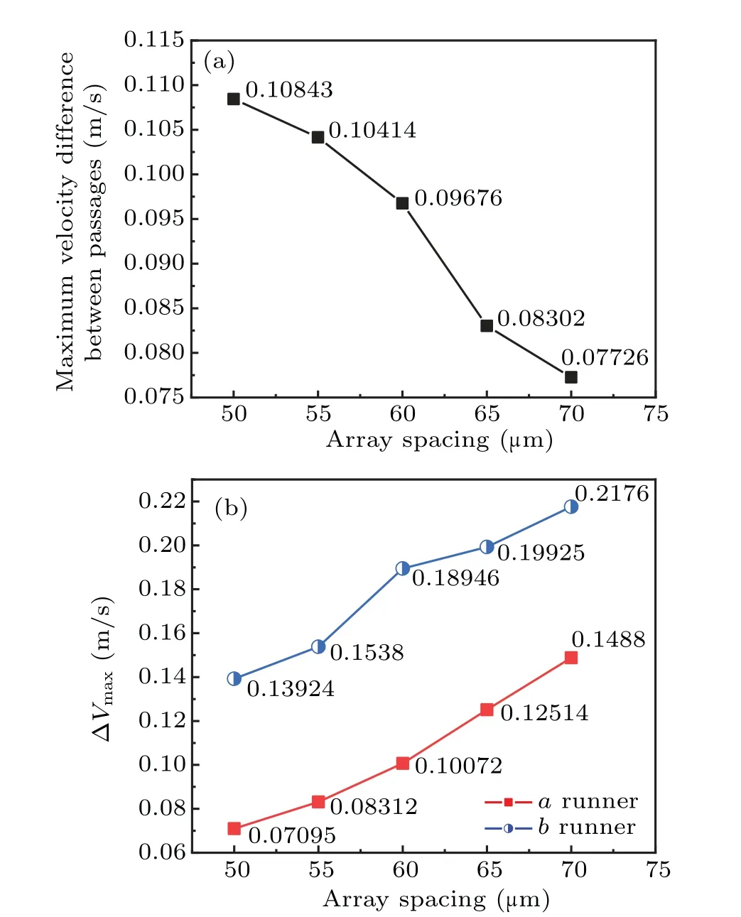
Fig. 3. Calculate the velocity values in each flow channel of five CRACs. (a) Maximum speed difference between the flow channels in the vertical direction of CRACs. (b) Maximum speed difference in CRAC channel a and channel b.
Then further compare the internal flow fields of the five CRACs. According to the calculations, when the inlet velocity was set to be 0.18 m/s,the maximum velocity of each subchannel in theXandYdirections was calculated separately,and the difference was taken according to the demand. The maximum velocity difference in the vertical direction(ΔVmaxy)between the five columns of CRAC is shown in Fig.3(a). As shown in Fig. 3(b), ΔVmaxais the maximum speed difference of channela,and ΔVmaxbis the maximum speed difference of channelb.
In the analysis of Fig. 3, it can be found that, as the array spacing increases, the maximum velocity difference between the flow channels of CRAC changes in opposite direction to the velocity difference between the flow channels ofaandb. According to Fig.3(a), as the array spacing increased from 50 µm to 70 µm, ΔVmaxydecreased from 0.10843 m/s to 0.07726 m/s. However, as shown in Fig. 3(b), ΔVmaxaincreased from 0.07095 m/s to 0.1488 m/s, while ΔVmaxbincreased from 0.13924 m/s to 0.2176 m/s. It can be found that the velocity distribution in the channel was the most uniform when the array spacing was set to be 60µm.
3.3. Optimization of velocity field distribution in the channel
For semi-packed micro GC columns, the position structure of the micro-packed posts embedded in the channel has a great influence on the velocity field inside the channel. Ali studied the effects of three different cross-sectional shapes such as square, diamond and long hexagon on the velocity field in the channel.[12]The study found that the abnormity of the long hexagonal packed column was significantly improved compared to the rhomboid packed column. In the process of coating the stationary phase,the micro GC column with long hexagon and square packed column structure causes the pressure inside the channel to increase sharply, which makes the stationary phase coating fail. In order to improve the problem of non-uniform velocity field in the channel of the GC column, some researchers had proposed a micro-packed column with an elliptical cross-sectional shape.The micro-packed column structures in the above studies all adopted the traditional rectangular array arrangement.
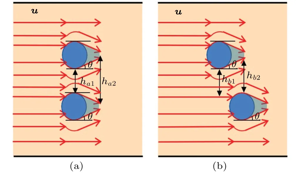
Fig. 4. Schematic diagram of gas flow around a cylinder. The red arrows represent the direction of flow. The blue area is cylinder and the light blue area is retention area. u is the linear velocity of the micro fluid in the flow field.
This article tries to explain the formation of virtual wall and the generation of velocity fluctuation at the physical level.As shown in Fig.4,by streamlining the fluid flow in the flow field, when the gas bypasses the cylinder, part of the gas velocity direction is affected by the cylinder. The gas will flow along the tangent direction of the cylinder with an angle ofθ,and it will form a retention zone with no fluid flow.

According to the continuity equation of fluid flow,it can be found that in the absence of leakage and replenishment of the pipeline, the mass of the fluid flowing into any section is equal to that of the fluid flowing out of another section,

whereρis the density of the micro fluid,A1is the crosssection area at the inlet, andA2is actual cross-sectional area where the fluid is aftertseconds. In this paper,the continuity equation can be rewritten according to the reality because the height the cross section(l)is the same,

Since there is a difference betweenh2andh1,it can be found that there is a difference betweenu2andu1. From the comparison between Eqs.(5)and(6),the following inequality can be derived:
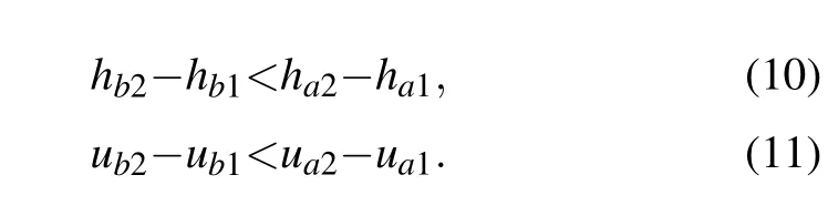
According to the deduced results,it can be found that displacing the second row of cylinders backward can effectively reduce the width difference of the actual fluid in the flow process. Therefore, the velocity fluctuation in the flow channel can be effectively reduced. In this paper, micro-packed columns arranged in a staggered array are introduced to improve the velocity field(Fig.5).
With the initial speed set to be 0.18 m/s and the array spacing is 60µm,the internal channel flow field of five semipacked micro gas chromatography columns including CSAC1,CSAC2, CSAC3, CSAC4 and CSAC5 was analyzed. From Fig. 5, it can be found that as the dislocation spacing increases, the velocity fluctuations in the flow channel are obviously suppressed. In order to further quantitatively analyze the speed difference between the four flow channels divided into the micro-packed column and the speed difference in the four flow channels. This paper calculates the velocity values in four channels of five sets of CSAC. The maximum speed difference of the five groups of CSAC in the vertical direction is observed in Fig.6(a),and the maximum speed difference in channelsaandbis shown in Fig.6(b).

Fig.5. The flow field analysis module in the COMSOL Multi-physics software was used to analyze the flow field in channels of CSACs. (a)CSAC1 flow field distribution. (b) CSAC2 flow field distribution. (c)CSAC3 flow field distribution. d) CSAC4 flow field distribution. (e)CSAC5 flow field distribution.
According to Fig.6,as the dislocation spacing increased from 10 µm to 50 µm, ΔVmaxyof CSAC structures decreased from 0.08594 m/s to 0.0561 m/s and then increased to 0.0996 m/s. The ΔVmaxadecreased from 0.1082 m/s to 0.0916 m/s and then increased to 0.1159 m/s,and the ΔVmaxbdecreased from 0.13619 m/s to 0.02401 m/s and then increased to 0.1614 m/s.
Therefore, considering the maximum speed difference between the runners and the speed difference in the channelsaandb, it was optimal when the displacement distance was 30µm.
系统基于油田公司WEB平台,采用.NET MVC技术架构开发,客户端采用Bootstrap JS框架实现页面布局,服务端采用JQuery Ajax、TheadPool多线程并发,曲线发布采用HighCharts控件,系统目前运行稳定可靠、执行效率高。
Finally,we comprehensively verify that the staggered array can effectively improve the uniformity of velocity distribution in the flow field. We choose a staggered structure with an array spacing of 60 µm and a staggered spacing of 30 µm to compare with the traditional rectangular array structure with an array spacing of 60µm. In other words,the velocity in the cross section of CSAC3 and CRAC3 was compared.
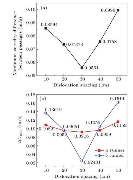
Fig.6. Calculate the velocity values in each flow channel of five CSAC.(a)Maximum speed difference between the channels in the vertical direction of the CSACs. (b)Maximum speed difference in CSAC channel a and channel b.

Fig. 7. Compare the flow field velocity distribution of CSAC3 and CRAC3 profiles. (a) CSAC3 profile velocity value. (b) CRAC3 profile velocity value.
The direction along the flow channel is defined as theXdirection, and the direction of the vertical flow channel is theYdirection. We takeX= 0.47 mm;X= 0.48 mm;X=0.49 mm;X=0.50 mm and other four groups of crosssection velocity values for calculation. From the comparison between Figs. 7(a) and 7(b), it was found that the curve consistency of CSAC3 is higher than that of CRAC3.
By combining Figs.3,6,and 7,it can be found that compared with the traditional rectangular array semi-packed structure, the ΔVmaxydecreased from 0.09676 m/s to 0.0561 m/s.The ΔVmaxadecreased from 0.10072 m/s to 0.0916 m/s, and ΔVmaxbdecreased from 0.18946 m/s to 0.02401 m/s.
In the previous studies, some scholars proposed the design of the filled column with elliptical section and simulated the flow field in the channel of the semi-packed gas chromatographic column with elliptical section.[23]A more uniform velocity distribution can be obtained by filling the column with an elliptical section. On the basis of the previous study, the length of the long axis and the length of the short axis of the elliptical filled column were set to be 40 µm and 30 µm, respectively, and the array spacing was 60 µm. The velocity fields under staggered arrangement and rectangular array were compared and analyzed respectively. The results are shown in Fig.8.
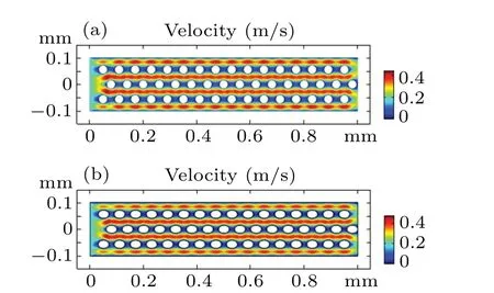
Fig. 8. Using the flow field analysis module in COMSOL Multiphysics software, the flow field in the channel of elliptic semi-packed column with rectangular array and staggered array was analyzed. The flow field distribution of the rectangular array is shown in the figure above,and the flow field distribution of the staggered array is shown in the figure below.
In order to further study the influence of staggered array layout on the velocity field,the maximum velocity difference in the channel under staggered array and rectangular array was calculated in this paper. In the case of rectangular array, the ΔVmaxyis 0.05776 m/s, the ΔVmaxais 0.08417 m/s, and the ΔVmaxbis 0.14925 m/s. In the case of setting the interlaced spacing at 30 µm , the ΔVmaxyis 0.04653 m/s, the ΔVmaxais 0.07887 m/s, and the ΔVmaxbis 0.02711 m/s. Therefore, the staggered array structure improved the uniformity of the flow field of the semi-packed GC column with elliptical cross section.
3.4. Pressure field distribution in the channel
It has been mentioned in previous studies that the smaller the array spacing of the micro-packed columns embedded inside the channel, the greater the pressure inside the channel,and the higher the requirement for the gas carrier system of the gas chromatograph.[25]Using a rational structure design to reduce the pressure distribution inside the channel has a positive effect on the miniaturization process of the chromatograph. In this paper,the channel structure of CSAC1,CSAC2,CSAC3 and CRAC3 with a length of 1 mm was used for comparative study of pressure distribution(Fig.8). The maximum pressure in the column of CSAC3 was only 48.5 Pa, which has a better performance in terms of energy saving than other CSACs structures. The maximum pressure value of CSAC2 was 50.1 Pa;CSAC1 was 52.5 Pa,and CRAC3 was 53.5 Pa.
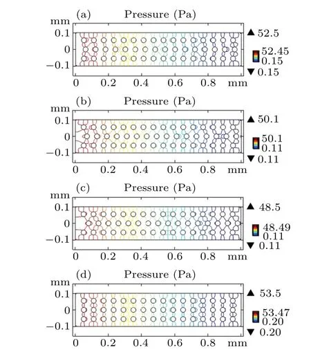
Fig. 9. Calculate the pressure distribution of CSAC1, CSAC2, CSAC3 and CRAC3. (a)CSAC1 pressure distribution. (b)CSAC2 pressure distribution.(c)CSAC3 pressure distribution. (d)CRAC3 pressure distribution.
4. Conclusion and perspectives
Based on the MEMS technology,a staggered array semipacked micro GC column structure was proposed. The velocity field distribution and pressure distribution in the channel of ten semi-packed micro GC column structures were studied.The results show that as the array spacing increases within a certain range, the maximum velocity difference between the flow channels in the vertical direction gradually decreases,and the maximum velocity difference between the channels a and b increases. Compared with the traditional semi-packed rectangular array structure, the optimal staggered array structure proposed in this paper reduced the ΔVmaxyfrom 0.09676 m/s to 0.0561 m/s. The ΔVmaxawas reduced from 0.10072 m/s to 0.0916 m/s, and the ΔVmaxbwas reduced from 0.18946 m/s to 0.02401 m/s. Therefore,in the design of the micro GC column structure,the overall uniformity of the velocity field in the channel can be improved by reducing the array spacing. The semi-packed micro GC column structure of the staggered array proposed in this paper had more uniform velocity distribution,whether it was filled with a circular section or an elliptical section.Using the staggered array structure can effectively improve the pressure distribution in the channel compared with the traditional rectangular array structure.In a sense,the structure design method we proposed provides a theoretical basis for exploring new micro GC column structures.
Acknowledgements
Project supported by the Natural Science Foundation of Jiangsu Province, China (Grant No. BK20180098), National Laboratory of Solid State Microstructures,Nanjing University(Grant Nos.M32045 and M33042).
猜你喜欢
杂志排行

Chinese Physics B的其它文章
- Superconductivity in octagraphene
- Soliton molecules and asymmetric solitons of the extended Lax equation via velocity resonance
- Theoretical study of(e,2e)triple differential cross sections of pyrimidine and tetrahydrofurfuryl alcohol molecules using multi-center distorted-wave method
- Protection of entanglement between two V-atoms in a multi-cavity coupling system
- Semi-quantum private comparison protocol of size relation with d-dimensional GHZ states
- Probing the magnetization switching with in-plane magnetic anisotropy through field-modified magnetoresistance measurement