Probing the magnetization switching with in-plane magnetic anisotropy through field-modified magnetoresistance measurement
2022-01-23RunrunHao郝润润KunZhang张昆YinggangLi李迎港QiangCao曹强XueyingZhang张学莹DapengZhu朱大鹏andWeishengZhao赵巍胜
Runrun Hao(郝润润) Kun Zhang(张昆) Yinggang Li(李迎港) Qiang Cao(曹强)Xueying Zhang(张学莹) Dapeng Zhu(朱大鹏) and Weisheng Zhao(赵巍胜)
1Fert Beijing Institute,MIIT Key Laboratory of Spintronics,School of Integrated Circuit Science and Engineering,
Beihang University,Beijing 100191,China
2Beihang-Goertek Joint Microelectronics Institute,Qingdao Research Institute,Beihang University,Qingdao 266000,China
3Spintronics Institute,University of Jinan,Jinan 250022,China
4Truth Instruments Co. Ltd.,Qingdao 266000,China
Keywords: magnetoresistance,in-plane magnetization switching,electrical detection
1. Introduction
In recent years, intensive attention has been paid to the 3-terminal spintronic device with information written by the spin-orbit torque (SOT) effect, which allows a high writing speed without incubation delay and has an enhanced endurance benefiting from the separated read/write routes.[1-3]One typical SOT device employs a heavy metal/ferromagnet(HM/FM) heterostructure as the basic function structure for the information writing,where the spin current induced by an in-plane charge current via the spin-orbit interactions(SOI)of the HM layer will exert spin torques on the magnetization and drive magnetization switching of the adjacent FM layer.[4-9]In terms of the easy-axis direction of the FM layer,the SOT devices mainly take one of the two configuration types:the easyaxis perpendicular to the film plane,[6,10,11]or, the easy-axis lying in the film plane and orthogonal to the charge current.[4]A lot of experimental techniques, such as spin torque ferromagnetic resonance(ST-FMR)or harmonic Hall experiments,have been developed to characterize the SOT efficiency in these devices.[12-17]
On the other hand, the SOT-induced magnetization switching is technologically more relevant to the device applications,thus the efficient probing of the SOT-induced magnetization switching is also of great significance. For the FM with perpendicular magnetic anisotropy(PMA),the magnetization switching can be easily probed by measuring the anomalous Hall effect (AHE).[5,6,18]However, for the FM with in-plane magnetic anisotropy (IMA), the Hall voltage or magnetoresistance (MR) measurements can not evidence the magnetization switching due to their equal resistance values for opposite magnetization orientations. The SOTinduced magnetization switching in the HM/FM heterostructure with IMA are typically probed by giant magnetoresistance (GMR)/tunneling magnetoresistance (TMR) in a spin valve structure.[19,20]The complicated device fabrication process hinders this technique being developed into a widely used approach to detect SOT switching. The magneto-optic Kerr effect (MOKE) imaging technique can also probe in-plane magnetization switching,[21,22]but suffers drawbacks of being applicable only to the devices with thin capping and having bad capability with low temperature and strong magnetic field.A convenient access to probe the SOT-induced magnetization switching of an FM with IMA is still highly desired.
For FM with IMA,there is no difference in resistance for the magnetization oriented to opposite directions, as shown in Fig. 1(a). If a magnetic field (H) is applied to break the symmetry of the MR signal,the difference in resistance arises,i.e.,high-resistance-state(high-Rstate)or low-resistance-state(low-Rstate)occurs for the magnetization antiparallel or parallel toH, respectively,[23]as shown in Fig. 1(b). Inspired by this principle, we provide a convenient electrical strategy to probe the SOT-induced magnetization switching with IMA.For the material system with strong field-like SOT,[24]the resulting effective field when current flowing through HM would break the symmetry and result in resistance difference for opposite magnetization orientations, thus allowing the electrically probing of the magnetic state. Furthermore, an appropriate external magnetic field can replace the field-like effective field to modify the MR signal, which is suitable for more extensive material systems,not only the one with strong field-like torque. We observe clear SOT switching loops and demonstrate the feasibility of these methods in probing the SOT driven magnetization switching in various systems of Pt/NiFe,W/CoFeB and Bi2Se3/NiFe Hall bars with IMA.The method with MR modified by an external magnetic field enables a small reading current, which can avoid thermal noise and possible even damage on microstructure device due to the persistent Joule heating. This work provides an effective and reliable method to electrically characterize the in-plane magnetization switching in a simple Hall bar,which can facilitate the study of SOT-related effect.

Fig.1. Schematic diagrams of resistance states of FM layer for magnetization oriented to opposite directions(a)without or(b)with a modifying field.
2. Experimental details
The Pt(6)/Ni20Fe80(8)and W(5)/Co20Fe60B20(1.9)bilayers(the thicknesses in the parentheses are in nanometers)are prepared on thermally oxidized Si substrates with a magnetron sputtering system at room temperature, and the base pressure is better than 5×10⁻⁶Pa. As for the Bi2Se3(8)/Ni80Fe20(3.5)bilayers, the high-quality Bi2Se3films are grown on Al2O3(0001) substrates in a molecular beam epitaxy (MBE) system with a base pressure better than 2×10⁻⁷Pa, by using the two-step deposition procedure,and then the Ni80Fe20film is subsequently sputtered on the Bi2Se3film at room temperature. For MR and SOT switching measurements, the as-deposited films are patterned into Hall bars with channel sizes of 10µm×80µm through photolithography and Ar ion milling processes. All measurements are performed at room temperature using a home-made magneto-electrical transport measurement system. A current source of Keithley 6221 and a nano-voltmeter of Keithley 2182 are used to supply dc read currents (Iread) and detect dc voltages (V), respectively.The longitudinal resistanceRxx=V/Iread. The pulse currents(Ipulse)with pulse duration of 10µs for switching the magnetization are supplied by Keithley 4200.
3. Results and discussion
The MR measurement with a four-point probe method for Pt/Ni20Fe80is schematically shown in Fig. 2(a). We inject the charge current(includingIreadandIpulse)and measure the voltage alongxaxis with external magnetic fieldsHextsweeping alongyaxis. As shown in Fig. 2(b), the magnetization of the Pt/Ni80Fe20is characterized by MR measurement withIread=-0.1 mA,and the coercive field of about 5.2 Oe is obtained. The normalized MR loops withIread=±4 mA are shown in Fig. 2(c). ForIread=±4 mA, obvious horizontal shifts of the MR peaks are observed, indicating the existence of a current-induced effective fieldHCEF.[25-27]The critical magnetization switching fieldsHSWfor differentIreadare shown in Fig. 2(d), whereH+SWorH-SWare the critical magnetization switching fields for external fields sweeping from-yto +yor from +yto-y, respectively. We find thatH+SWandH-SWare both proportional to the value ofIread, andHCEF=(H+SW+H-SW)/2 is reversed when the sign ofIreadis changed. For|Iread|=4 mA,the Oster fieldHOeinduced acting on the Ni80Fe20layer is calculated to be much smaller thanHCEF≈2.5 Oe. Hence, the horizontal shift in the MR loop mainly origins from the field-like effective field induced by the SOT effect.
The magnetization switching measurements of the Pt/Ni80Fe20Hall bar with the modification ofHCEFare performed. Figures 3(a)and 3(b)illustrate the process diagrams of these measurements. The pulse currentIpulsesweeps from negative to positive values and back to negative values. After each of pulse currents,read currents ofIread=±3 mA are injected to modify MR signals and detect the corresponding voltages.The longitudinal resistanceRxxversus pulse currentIpulseis shown in Figs.3(c)and 3(d). It is found thatRxxswitches to the high-Rstate or low-Rstate at critical switching pulse currents ofIpulse≈∓5.5 mA,respectively. The measured critical switching current is well reproducible after several switching cycles. And the polarities of the pulse current-induced switching loops are opposite forIread=±3 mA.The origin of variation inRxxwhen the magnetization switching takes place is schematically shown in Figs.3(e)and 3(f). Under the modification of largeHCEF, the states with magnetization along±ydirections have differentRxxvalues. When the damping-like torque induced by theIpulseis large enough to overcome the intrinsic damping and switches the magnetization,a variation inRxxoccurs with the modification ofHCEF.
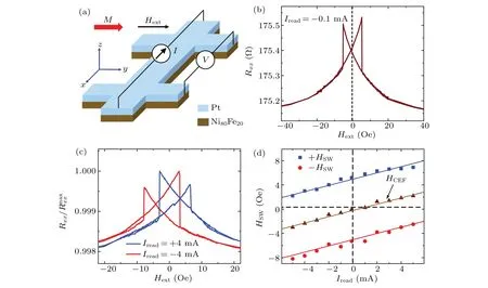
Fig.2. (a)Schematic illustration of the Pt/Ni80Fe20 Hall bar device with channel size of 10µm×80µm and MR measurement. The positive direction of current is defined along the-x direction,and the positive direction of the external magnetic field is defined along the+y direction.(b)The MR loop for Pt/Ni80Fe20 Hall bar with Iread =-0.1 mA.(c)The shifted MR loops for Pt/Ni80Fe20 Hall bar with Iread =±4 mA.(d)The critical switching field HSW versus read current Iread for Pt/Ni80Fe20 Hall bar. The HCEF =(H+SW+H-SW)/2, where H+SW or H-SW are the critical switching fields for external field Hext sweeping from-y to+y or from+y to-y,respectively.
As can be seen from the above results, the MR modified byHCEFcan be used to probe SOT-induced switching in the heterostructure with IMA.Note that the requirement for a sizeableHCEFmay be an important limitation for this method. For the stacks with smallHCEF,[12,28]there is no significant difference inRxxfor opposite magnetization orientations. This limitation can be eliminated by introducing an appropriate external assisting fieldHassist. Next,we demonstrate the probing of SOT-induced magnetization switching of the Pt/Ni80Fe20heterostructure under the modification ofHassist. The process diagrams of the switching measurements with the assisting fields ofHassist=∓1.2 Oe are illustrated in Figs. 4(a) and 4(b), respectively. The pulse currentsIpulsesweep from negative to positive values and back to negative values. After each ofIpluse,a small read current ofIread=+0.1 mA and anHassistare applied simultaneously to detect the corresponding resistance.As shown in Fig.4(c),withHassist=-1.2 Oe,theRxxswitches to low-Rstate at aroundIpluse=+5.5 mA,and it switches back to high-Rstate at aroundIpluse=-5.5 mA.And the polarities of switching loops change with the sign reversal ofHassist, as shown in Fig.4(d).The origin of difference inRxxbetween the opposite magnetization orientations is schematically shown in Figs.4(e)and 4(f).For|Iread|=0.1 mA,theHCEFis negligibly small as shown in Fig.2(b).TheHassistplays the similar role in modifyingRxxto that ofHCEF,where theRxxvalue depends on the relative orientation between the magnetization andHassist.Comparing the above two methods,the former one that modified byHCEFrequires a relatively simple equipment, but is infeasible for the systems with small field-like torque. In addition,the required giant reading current and subsequent persistent Joule heating may introduce remarkable thermal noise and even damage the microstructure device. In contrast, the latter one that modified byHassistallows a small read current and caters for more extensive material systems,which is a universal,reliable and effective method.
Based on the measured results,we can estimate the SOT efficiency of the Pt/Ni80Fe20heterostructure. The field-like SOT efficiency(ξFL)can be written as[29,30]

whereMS,tNiFe,µ0Mk, andJPtare the saturation magnetization, thickness of the Ni80Fe20layer, demagnetization field,and current density flowing in the Pt layer,respectively.TheHFL=HCEF-HOeis the field-like effective field acting on the Ni80Fe20layer, which is proportional toJPt. With pulse current duration ranging from 5 µs to 0.5 s, the critical switching current almost keeps a constant. Therefore,the zero-thermal-fluctuation critical switching current densityJc0should be approximately equal to the critical switching current densityJcfor our sample.[33]The damping constantα0≈0.015 andµ0Mk≈0.92 T are determined by ferromagnetic resonance (FMR) measurements. With Eqs. (1)and (2), the field-like SOT efficiencyξFL= 0.01 and the damping-like SOT efficiencyξDL=0.23 are obtained for the Pt/Ni80Fe20heterostructure, respectively. The calculatedξFLandξDLare comparable to the values reported in previous works.[25,30,34,35]

Fig. 3. The magnetization switching measurement with MR modified by the current-induced effective field HCEF for Pt/Ni80Fe20 Hall bar.(a),(b)The measurement processes for the switching experiments with read currents of Iread=±3 mA,respectively. (c),(d)The variation in resistance versus pulse current with Iread =±3 mA,respectively. (e), (f)The difference in resistance for opposite magnetization orientations with positive and negative read currents,respectively.

Fig. 4. The magnetization switching measurement with MR modified by the external magnetic field for Pt/Ni80Fe20 Hall bar. (a), (b) The measurement processes for switching experiments with read current of Iread=+0.1 mA.During the measurements of Rxx,the assisting fields of Hassist=∓1.2 Oe are applied,respectively. (c),(d)The variation in resistance versus pulse current with assisted fields of Hassist=∓1.2 Oe,respectively. (e),(f)Schematic diagrams of difference in resistance for opposite magnetization orientations under the modification of negative and positive assisting fields,respectively.

Fig.5.(a),(b)The variation in resistance versus pulse current for W/Co20Fe60B20 Hall bar with assisted fields of Hassist=∓1.7 Oe,respectively.(c),(d)The variation in resistance versus pulse current for Bi2Se3/Ni80Fe20 Hall bar with assisted fields of Hassist=∓1 Oe,respectively.
To further verify the feasibility and application range of our method, the magnetization switching measurements withRxxmodified by theHassistare also performed in different material systems. TheRxxversus the magnetic field of a W/Co20Fe60B20Hall bar withHassist=∓1.7 Oe is shown in Figs. 5(a) and 5(b), respectively. The switching ofRxxbetween high-Rstate and low-Rstate takes place atIpluse=±6.8 mA. The polarities of the switching loops are reversed when the HM layer is changed from Pt to W forHassistwith the same sign since Pt and W possess opposite signs of the spin Hall angle. It is worth noting that the measured signal of W/Co20Fe60B20in our experiments is comparable to that of Pt/Ni80Fe20.[36]Meanwhile,the anisotropy MR(AMR)ratio of Co20Fe60B20single layer is about one order smaller than that of Ni80Fe20.[37,38]These results mean that the spin MR(SMR),proportional to the square of the HM layer’s spin Hall angle,[23]plays a dominant role in the electrical measurement of magnetization switching in the W/Co20Fe60B20sample. Therefore, our method is suitable for various FM materials,even those with weak common AMR.Furthermore,our method is extended to the emerging topological insulator of Bi2Se3with large charge-to-spin conversion efficiency and the magnetization switching measurements of Bi2Se3/Ni80Fe20Hall bar are performed.[39]The clear switching ofRxxat|Ipluse|=3.4 mA withHassist=∓1 Oe is observed in Figs.5(c)and 5(d),respectively. With Eq.(2),the damping-like SOT efficiencyξDLof Bi2Se3/Ni80Fe20is estimated to be 0.91 which is roughly consistent with the previous report.[22]The above results strongly demonstrate that our method can be used to effectively determine the SOT efficiency for various material systems with IMA.
4. Conclusion
In summary, with the modification of a current-induced effective field or an external assisting field,the switching symmetry of MR is broken and the difference in resistance is induced for opposite magnetization orientations, allowing the electrical probing of in-plane magnetization switching in a simple Hall bar device. The method by utilizing an assisting field can be employed for various material systems, even for that without current-induced field-like SOT field. Our results extend the approaches to determine the SOT switching in the heterostructures with IMA,and will contribute to the research about SOT-based memory and computation.
Acknowledgements
Project supported by the National Natural Science Foundation of China(Grant Nos.11904017,11974145,51901008,and 12004024),Shandong Provincial Natural Science Foundation,China(Grant No.ZR2020ZD28),platform from Qingdao Science and Technology Commission, and the Fundamental Research Funds for the Central Universities of China.
猜你喜欢
杂志排行

Chinese Physics B的其它文章
- Superconductivity in octagraphene
- Soliton molecules and asymmetric solitons of the extended Lax equation via velocity resonance
- Theoretical study of(e,2e)triple differential cross sections of pyrimidine and tetrahydrofurfuryl alcohol molecules using multi-center distorted-wave method
- Protection of entanglement between two V-atoms in a multi-cavity coupling system
- Semi-quantum private comparison protocol of size relation with d-dimensional GHZ states
- Majorana zero modes,unconventional real–complex transition,and mobility edges in a one-dimensional non-Hermitian quasi-periodic lattice