Wavelength and sensitivity tunable long period gratings fabricated in fluid-cladding microfibers
2022-01-23WaJin金娃LinkeZhang张林克XiangZhang张祥MingXu徐铭WeihongBi毕卫红andYuefengQi齐跃峰
Wa Jin(金娃) Linke Zhang(张林克) Xiang Zhang(张祥)Ming Xu(徐铭) Weihong Bi(毕卫红) and Yuefeng Qi(齐跃峰)
1Key Laboratory for Special Fiber and Fiber Sensor of Hebei Province,Qin Huangdao 066004,China
2School of Information Science and Engineering,Yanshan University,Qin Huangdao 066004,China
Keywords: fluid-cladding microfiber,long-period grating,temperature
1. Introduction
A long-period grating in a single-mode fiber demonstrates a resonance at a specific wavelength in the transmission spectrum by coupling energy from the fundamental mode to the cladding mode of the fiber. However,the geometry and material constraints of conventional fiber impose significant limitations on the functions that a long-period grating can achieve.[1]For example, it is difficult to realize a widely tunable filter at room temperature and highly sensitive sensor. To design a wavelength tunable long-period grating, some configurations are proposed, such as applying mechanical pressure to a long-period holey-fiber grating,[2]temperature to a complicated fiber structure containing air rings in the cladding filled with polymer[3]and fabricating a long-period grating in a BGe doped fiber by a careful choice of a high-order cladding mode,[4]however,the wavelength tunability is not permanent because the wavelength shift disappears without the changed environment.

In this paper, a fluid-cladding microfiber is proposed to achieve the wavelength tunability of long-period gratings by changing the fluid material of cladding directly at room temperature, which avoids changing temperature, applying mechanical pressure and inducing complicated operation on the fiber, and is more practical for real-world applications. A long-period grating in water cladding microfiber is fabricated by scanning a focused femtosecond infrared laser periodically across the surface of the microfiber,which demonstrates a resonant attenuation of 28.53 dB with 10 pitches at wavelength of 1588.1 nm. When the cladding material of water is changed to alcohol solution with concentration of 5% and refractive index oil ofn=1.33, the resonance wavelength of the longperiod grating shifts to 1594.1 nm with resonant attenuation of 35.9 dB and 1575.1 nm with resonant attenuation of 24.91 dB,respectively. To illustrate the flexible sensing applications of this fluid cladding microfiber long-period grating, temperature sensing characteristics of these three different cladding microfiber long-period gratings are measured, which demonstrate different sensitivities of-0.524 nm/°C,-0.767 nm/°C and-1.316 nm/°C,respectively.
2. Experimental results and discussion
The microfiber is fabricated by bi-tapering a conventional single mode fiber. A laboratory flame taper machine with movable flame is setup in our experiment to fabricate a microfiber with long uniform length,as shown in Fig.1. The two pigtails of a single mode fiber are mounted on two three-axis translation stages, and a hydrogen flame with a diameter of 10 mm is used to heat and soften the fiber. The flame is scanning along the fiber back and forth with a scan length ofLand a velocity ofVS, while the two translation stages move in the opposite direction with the same velocityVP. This lab-made machine can draw a microfiber with uniform length of 8 cm and diameter of~1µm.
A 5 cm-long and~5µm-diameter microfiber is used in our experiment, which is inserted into a capillary tube. The microfiber is kept straight and suspended along the center line of the capillary tube while its single mode fiber pigtails are glued to the two ends of the capillary. The capillary used in our experiment has inner and outer diameters of~660 µm and~900 µm, respectively. During the process of tapering and encapsulation,the transmission spectrum of the microfiber is monitored by connecting the input and output single mode fiber pigtails respectively to a broadband light source and an optical spectrum analyzer,and a large transmission loss is observed if the microfiber is broken or adhered to the inner wall of the capillary. A loss of~0.2 dB is achieved with a capillary containing the microfiber, which shows that the encapsulation does not change the optical property of the microfiber but the capillary tube protects the microfiber from external disturbance and contamination and makes it more robust.
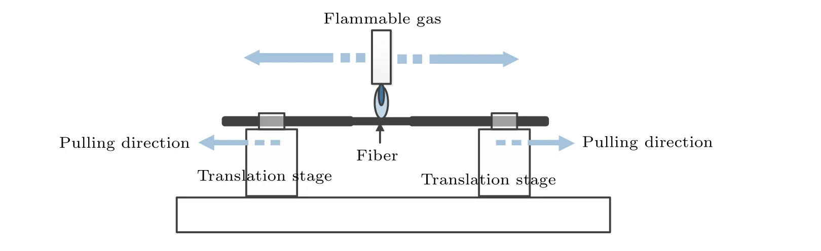
Fig.1. Schematic figure of lab-made taper machine.
Two side holes are drilled on the capillary wall, which act as ingress/egress channels for sample fluids. One hole on the capillary wall is immersed into water while the other hole is left open to the air, and the section between the two sideholes is filled with water in a few seconds via capillary effect,as shown in the inset of Fig. 2. Such structure is robust and stable, and can be easily integrated into standard fiber-optic circuits with low loss, making the fluid cladding microfiberbased devices more practical for real-world applications.
The LPG is fabricated by a point-by-point technique. The encapsulated liquid cladding microfiber is mounted on two computer-controlled three-dimension translated stages. The input and output pigtails of the single mode fiber from which the microfiber is made are connected respectively to a broadband light source and an optical spectrum analyzer. Femtosecond laser pulse is focused on the upper surface of a microfiber,and the irradiation intensity and diameter of the focal spot are respectively~0.15 J/cm2and 3 µm. The fabrication process is as following: firstly, the laser beam scans the microfiber transversely to fabricate the first point,then the focal spot moves longitudinal with a period to induce the second point, and the transmission spectrum of the long-period grating is monitored during fabrication process, as shown in Fig. 2. What we want to show here is that the long-period grating is directly fabricated in the fluid cladding microfibers by adjusting the focus and the energy of the femtosecond laser pulse,regardless of the capillary tube that encapsulates the microfiber and the fluid surrounding the microfiber. The encapsulation has little or no effect on the inscription.The red line in Fig.3 shows the transmission spectrum of a long-period grating made on an encapsulated microfiber with water cladding.The resonant wavelength is 1588.1 nm,and the strength of the attenuation dip is 28.53 dB.
To change the cladding material,the water is removed and cleared,and a new fluid material is filled into the same capillary tube. By use of a piece of absorbent paper to cover one of the holes on the capillary wall,the majority of water within the capillary can be removed within few seconds. The tube is then re-filled with 99.5%propyl alcohol to clean the left water fluid,which is removed by placing the absorbent paper on the hole. This process is repeated a number times and the capillary left in air for a few minutes to dry out the alcohol. Then the capillary tube is filled with 5% propyl alcohol solution,and a new long-period grating appears. The new resonance wavelength is 1594.1 nm, and the attenuation dip is 35.9 dB.When the cladding material is changed to a refractive index oil withn=1.33,the long-period grating shows resonance wavelength of 1575.1 nm and attenuation dip of 24.91 dB,as shown in Fig.3.

Fig.2. Experimental setup for fabrication long-period grating in water cladding microfiber with femtosecond laser. Inset: picture of the two ends of the capillary.
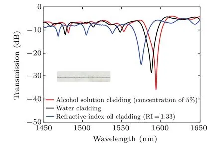
Fig. 3. Transmission spectra of long-period grating fabricated in microfibers with different kinds of fluid cladding.Inset:microscope image of long-period grating.
The modal property of microfibers with different claddings is studied by using a three-layer (a circular core,a circular silica rod with a fluid cladding) step-index model.Figure 4 demonstrates the mode property of the microfiber with water cladding. It is obviously that the microfiber with water cladding can support few guided modes, and hence a long-period grating is fabricated by coupling between the fiber modes.
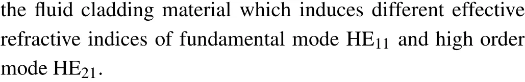

Fig.4. Guided modes in water cladding microfiber.
Based on the above equation,the phase-matching curves corresponding to the resonant coupling between the fundamental and the first group of higher-order modes with different fluid claddings are calculated for a microfiber with diameter of 5 µm and shown in Fig. 5. For a grating pitch of 70 µm, Fig. 5 predicts that three resonance dips of the three different fluid cladding microfibers would be formed around 1530 nm, 1543.6 nm, and 1550 nm, corresponding to coupling from HE11to HE21for refractive index oil cladding microfiber, water cladding microfiber, and 5% propyl alcohol solution cladding microfiber, respectively. The transmission spectrum matches well with the calculated results for HE11-HE21coupling with a pitch of 68.7 µm, the difference between the theoretical result and the experimental result may come from the little measurement deviation of diameter of the microfibers.
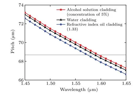
Fig. 5. Phase matching curves for microfibers with different fluid claddings.
As can be seen from Fig. 6, the refractive index difference between fundamental mode HE11and higher-order mode HE21in a microfiber becomes much larger with the diameter of the microfiber decreasing, thus the pitch achieving the phase match condition becomes much smaller, for example,when the refractive index of liquid cladding is 1.3,the pitch is about 30µm for the microfiber to achieve resonant wavelength of 1550 nm,while it is about 92µm for the same cladding microfiber with diameter of 6µm to achieve the same coupling.The resonant wavelength shifts to the longer wavelength with the refractive index of the liquid cladding increasing for the same microfiber, and the tunable range is much wider with the decrease of the diameter of the microfiber, for example,the resonant wavelength of 1.31µm shifts to 1.59µm for the microfiber with a diameter of 3 µm when the refractive index of the liquid cladding changes from 1.3 to 1.33,while the resonant wavelength of 1.51 µm shifts to 1.58 µm when the diameter of the microfiber is 6 µm. The tunable wavelength spans are 280 nm and 70 nm, respectively. The diameter and the flexible cladding make the tunable resonant wavelength of long-period grating fabricated in liquid cladding microfiber available.
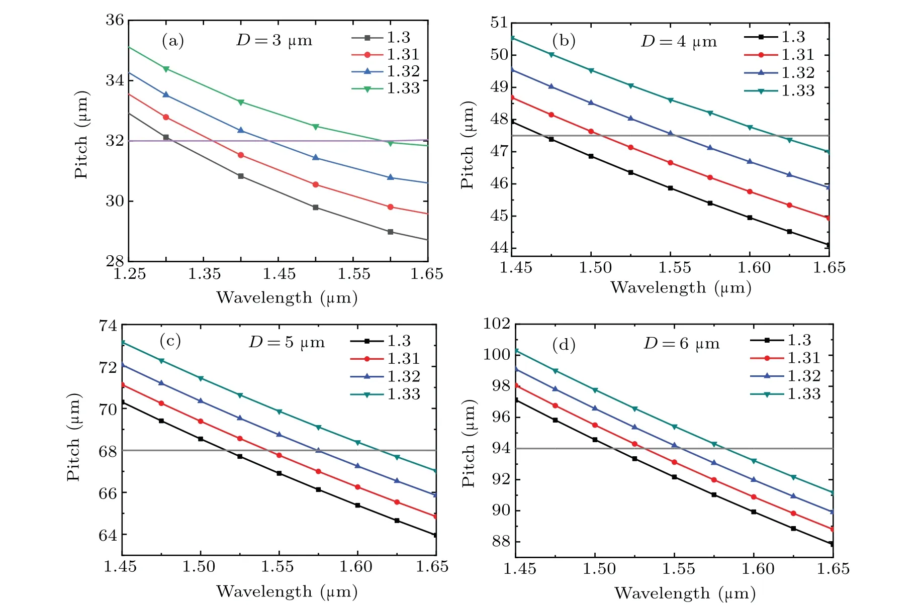
Fig.6. Phase matching curves for different refractive index fluid cladding microfibers with different diameters: (a)3µm,(b)4µm,(c)5µm,(d)6µm.
3. Sensing characteristics
The physical property of fluid cladding of microfiber can be used for sensing applications. The transmission spectra of this microfiber with different fluid cladding are monitored when the surrounding temperature is varied from room temperature to 45°C by use of a digital controlled oven. The resonance dips shift to short wavelength with the temperature increase, and the measured spectrum of the long-period grating fabricated in microfiber with water cladding is shown in Fig. 7(a). Different temperature sensitivities are achieved,-0.524 nm/°C,-0.767 nm/°C, and-1.316 nm/°C, respectively, corresponding to the long-period gratings fabricated in the same microfiber with water cladding, alcohol solution cladding, and refractive index oil cladding, respectively, as shown in Fig.7(b),which is higher than that of the other sensors,as shown in Table 1.
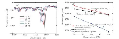
Fig.7. (a)Spectra evolution of long-period grating fabricated in water cladding microfiber. (b)Resonant wavelength as a function of temperature for different fluid cladding microfiber long-period gratings.
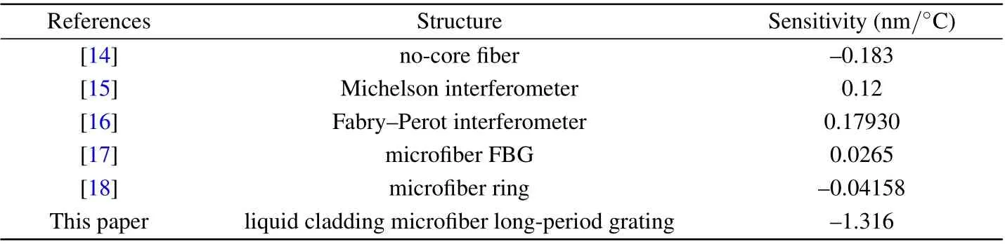
Table 1. Comparison of temperature sensitivities for different sensors.
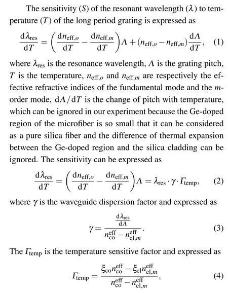
whereξcoandξclare the thermo-optical coefficients of core and cladding,respectively.
The water cladding microfiber is taken as an example,the resonant wavelength as a function of pitch is shown in Fig.8 under HE11and HE21coupling. It is obviously that when dλres/dΛ>0 the diameter of the fiber is smaller than 2µm,dλres/dΛ<0 when the diameter of the fiber is larger than 3µm,and dλres/dΛis turned from positive to negative when the diameter is increased from 2 µm to 3 µm. The similar analysis can be conducted for refractive index oil cladding and alcohol solution cladding.

Fig.8. Resonant wavelength as a function of pitch.
Thus the sensitivity as a function of normalized diameter(D/λ)for water cladding,alcohol solution cladding and refractive index oil cladding is calculated as shown in Fig.9,and the theoretical sensitivities are-0.588 nm/°C,-0.61 nm/°C and-1.06 nm/°C shown in the inset of Fig. 9, respectively. The experimental results are in good agreement with the theoretical results,and the little difference comes from the microfiber diameter measurement error and the little thermo-optical coefficient difference between theoretical data and actual data.

Fig.9. Sensitivity as a function of normalized diameter. Inset is sensitivity as a function of normalized diameter of 3.0 to 3.3.
4. Conclusion
We reported a simple wavelength and sensitivity tunable long-period grating fabricated in a fluid-cladding microfiber.A long-period grating in water cladding, refractive index oil cladding and alcohol solution cladding microfiber demonstrated a resonant attenuation of 28.53 dB at wavelength of 1588.1 nm,24.91 dB at wavelength of 1575.1 nm,and 35.9 dB at wavelength of 1594.1 nm, respectively, which are used for temperature measurement with different sensitivities. The alterable cladding material makes possible the realization of ultra wide-band tunable filters and variable sensors for different applications. We can envisage many new applications such as low loss evanescent-wave-coupled optical absorption, amplification,florescence,Raman and photoacoustic cells with this fluid cladding microfiber long-period grating by exploitation of many materials available for microfiber cladding. Realization of active devices and environmental sensors looks particularly promising.
Acknowledgements
Project supported by the National Natural Science Foundation of China (Grant Nos. 61605168 and 61735011), the Natural Science Foundation of Hebei Province, China(Grant Nos. F2016203392 and F2021203058), the College and University Science and Technology Research Project of Hebei Province, China (Grant No. QN2016078), and the Intramural Doctoral Foundation of Yanshan University (Grant No.B1011).
杂志排行

Chinese Physics B的其它文章
- Superconductivity in octagraphene
- Soliton molecules and asymmetric solitons of the extended Lax equation via velocity resonance
- Theoretical study of(e,2e)triple differential cross sections of pyrimidine and tetrahydrofurfuryl alcohol molecules using multi-center distorted-wave method
- Protection of entanglement between two V-atoms in a multi-cavity coupling system
- Semi-quantum private comparison protocol of size relation with d-dimensional GHZ states
- Probing the magnetization switching with in-plane magnetic anisotropy through field-modified magnetoresistance measurement