High-confinement ultra-wideband bandpass filter using compact folded slotline spoof surface plasmon polaritons
2022-01-23XueWeiZhang张雪伟ShaoBinLiu刘少斌LingLingWang王玲玲QiMingYu余奇明JianLou娄健andShiNingSun孙世宁
Xue-Wei Zhang(张雪伟) Shao-Bin Liu(刘少斌) Ling-Ling Wang(王玲玲)Qi-Ming Yu(余奇明) Jian-Lou(娄健) and Shi-Ning Sun(孙世宁)
1College of Electronic and Information Engineering,Key Laboratory of Radar Imaging and Microwave Photonics,Ministry of Education,Nanjing University of Aeronautics and Astronautics,Nanjing 211106,China
2AVIC Research Institute for Special Structures of Aeronautical Composite,Aviation Key Laboratory of Science and Technology on High Performance Electromagnetic Windows,Jinan 250023,China
Keywords: spoof surface plasmon polaritons(SSPPs),bandpass filter,ultra-wideband,high-confinement
1. Introduction
Surface plasmon polaritons (SPPs) are surface electromagnetic(EM)waves generated by the interaction of free electrons and incident field on the interface between metal and dielectric.[1,2]The metal can exhibit plasma properties in the near-infrared and optical wavebands,resulting in the presence of SPPs on the metal surface. The SPPs propagate along the metal surface with decay exponentially in the direction perpendicular to the surface. Its ability to overcome the conventional diffraction limit and manipulating light has a prevalent applications in photon circuits,such as SPPs waveguides,optical transmission, nonlinear optics, high sensitivity sensors,and other areas.[3-7]However, at low frequencies (e.g., microwaves or terahertz), the dielectric constant of the metal tends to infinity,which is usually approximately a perfect electric conductor(PEC).[8,9]Therefore, the binding of the metal surface to the EM wave is too weak to form the surface plasmons surface wave.
To solve this problem, the periodic structures, such as one-dimensional (1D) regular grooves and two-dimensional(2D) periodic holes arrays, are usually added to the surface of the metal. In 2004, Pendryet al.[10]demonstrated surface waves in 1D metal grooves and 2D periodic holes arrays. From the point of view of the new artificial EM media, the grooves and holes can be equivalent to a plasma material when the size of the grooves and holes is much smaller than the wavelength. And the surface wave has similar dispersion relation and sub-wavelength mimicking characteristics to the SPPs, which are called spoof surface plasmon polaritons(SSPPs).[10-12]In 2008,Williamset al.[13]experimentally verified the transmission characteristics of SSPPs in the terahertz band by machining 2D periodic through-holes on metal surfaces. And then, a variety of metal structured with various shapes have been proposed and proved to be able to support SSPPs such as helically grooves, wedge grooves, and diagonal grooves.[14-16]
Recently, researchers have done a lot of excellent research on SSPPs. The design of a guided wave system is one of the most critical problems for microwave and even THz frequency bands. In 2013, Cuiet al.[17]investigated flexible and conformal ultra-thin surface plasmonic waveguide(SPW),which provide a reliable basis for the processing and integration SSPPs transmission lines due to its good field confinement. Fenget al.[18]analyzed the trapezoidal groove structure and the SSPPs of high-order modes,and carried out in-depth research on their applications. Meanwhile, a large number of applications of SSPPs have been gradually carried out, including guided wave and surface wave conversion,[19]multiple mode analysis,[20]power splitter,[21,22]plasmonic circulator,[23]energy amplification,[24]filter,[25-28]radiation,and other aspects.[29-31]
The ultra-wideband(UWB)compact SSPPs bandpass filter has become an important development trend due to its essential role in modern integrated circuit and wireless communication systems. Hence, many efforts have been constructed SSPPs bandpass filters with high performance, such as micro-grooving waveguides,[20,22,32,33]coplanar waveguide(CPW),[28]half-mode substrate integrated waveguide,[34,35]and slotline SPW.[36-38]However,most of these SPW are still limitations in terms of enhanced confinement and compactness. Hence it is not convenient to be used as a carrier for microwave and THz signal transmission.
Here, a novel high-efficiency ultra-wideband SSPPs bandpass filter using compact folded slotline technology was designed. An efficient mode conversion structure between slotline and SSPPs waveguide is realized to efficiently transition the TE-mode and SSPPs mode.By changing the structural parameters of the SSPPs unit cells,the upper edge of the bandpass can be controlled easily.The proposed novel SSPPs structure with lower cutoff frequency and high-confinement capacity compared with the conventional plasmonic waveguides.CST software is used to simulate the effect of geometric parameters on transmission characteristics, surface current, dispersion relation for the fundamental SSPPs mode, near-field distribution, and power distribution of the proposed BPF. In addition,the prototype of the novel SSPPs BPF was fabricated and measured. The experimental results of the fabricated sample agree with the numerical simulation results well,showing the high-efficiency broadband transmission of the passband.The work paves the way toward high-confinement and miniaturized plasmonic devices for design and application.
2. Dispersion characteristics of proposed folded slotline SSPPs structure
Figure 1(a)shows the conventional SSPPs unit cell(type-A) with dipole metal grooves. The unit structure is arranged periodically in thex-direction. The metal grooves layer is printed on the 0.508-mm thick flexible dielectric substrate of Rogers (εr= 10.2, and tanδ= 0.0023). The metal is selected as the 0.035-mm thick copper (σ= 5.8×10⁷S/m).The dimensions of the structure indicated in Fig.1(a),Prepresents the period,wexpresses the width of the central slotline waveguide,hexpresses the depth of the grooves, andsrepresents the width of the vertical slotline. The transverseelectric (TE)polarized waves impinging at the surface of periodic units with thekx(kx>k0,k0is the wavenumber in free space), as shown in Fig. 1(a). Under the subwavelength dimensions(λ ≫P>a), the dispersion relation for the SSPPs modes in the array for the EM waves propagating along thexdirection is
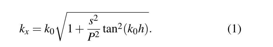
According to the dispersion relation for the SSPPs waveguide with traditional dipole grooves,the asymptotic frequency of the fundamental mode is inversely proportional to the depth of the rectangular slotline. Therefore, it is necessary to increase the depth of the rectangular slot line to obtain a lower asymptotic frequency, which will lead to the increase of the structure size.
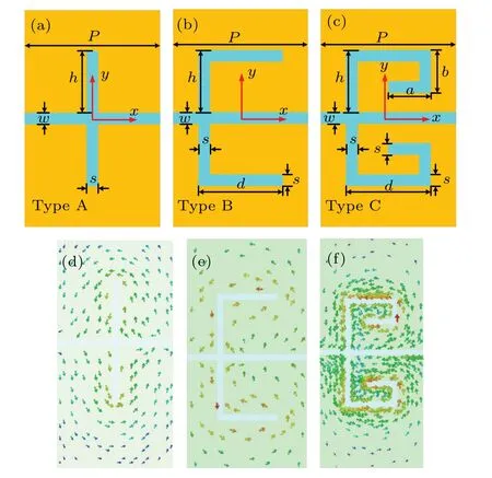
Fig. 1. Schematic diagram and simulated current distributions of different kinds of waveguides units. (a)The conventional rectangle slotline unit cell(type-A).(b)Rectangle slotline with branch parallel slot unit cell(type-B).(c) The proposed L-shape folded slotlines SSPPs unit cell (type-C). Simulated current distributions of(d)type-A,(e)type-B,and(f)type-C.
Figure 1(b) shows the SSPPs unit (type-B) etching of a branch parallel to the central slotline on the basis of the rectangular slotline in Fig.1(a). The main factor affecting the progressive frequency is the total length of the slot line. We further added L-shaped folded slotline to increase the total length of grooves without changing the overall structure size of the plasma waveguide based on type-B,as shown in Fig.1(c).The unit cell in Fig.1,aandbexpress the width and depth of the L-shape grooves,dexpresses the length of the branch slot line parallel to the central slotline waveguide. The detailed geometrical dimensions in Fig. 1 are:h=2,s=0.2,w=0.2,d=2,a=1.2,b=1,andP=4,(in unit mm).
The simulated surface current distributions of type-A,type-B,and type-C structural at 5.2 GHz are analyzed by the eigen mode calculation, as shown in Figs. 1(d)-1(f). It can be obtained that the current density aggrandizes stage by stage from type-A to type-C.The current mainly distributed periphery the L-shape folded slotline, resulting in the type-C unit can achieve a more significant slow-wave effect at the same frequency.

Fig. 2. The dispersion characteristics of different SSPPs unit cells with the same geometric size.
To obtain the dispersion curves,the dispersion characteristics for the fundamental SSPPs mode of the type-C,type-B,and type-A units with the same geometric size by the Eigen mode solver based on the FDTD and theoretical enumeration,are displayed in Fig. 2. In the numerical simulation, the periodic boundary condition is set in thexdirection,the perfect electric conductor (PEC) boundaries are placed in theyandzdirections, and the phase shift is set to the gradient variation,as shown in Fig.1. It can be observed that the dispersion curve of the type-C unit(see the rose line in Fig.2)more deviate from the light line than that of the type-B SSPPs unit and the conventional rectangle slotline, and the cutoff frequency decreases gradually from type A to type C.Figure 2 shows the asymptotic frequency is significantly reduced by increasing the branch slots parallel to the slotline waveguide,and further reduced by further growing the L-shaped slot,and the asymptote frequencies of type-A unit, type-B unit, and type-C unit are 9.4 GHz,6.4 GHz,and 5.3 GHz,respectively. In addition,the wave vector of the proposed type-C structure is the largest at the same frequency,which is stronger surface wave confinement, as shown in Fig.2. Thus, the introduction of side slotlines at slit waveguides can not only realize the transmission characteristics of slotline waveguides at different frequencies,but also realize the design of strongly confined miniaturized devices.
3. Design and analysis of the proposed SSPPs BPF
The schematic representation of the proposed novel SSPPs bandpass filter based on the analysis as mentioned above the fold slotline SSPPs (type-C) unit cells are shown in Fig. 3. The microstrip feeding lines with a circular plate and used to input,and output port are printed on the top layer as shown in Fig. 3(a), which is symmetric with abidance byyozplanes. The L-shape fold slot surface waveguide on the Rogers substrate with the thickness of 0.508 mm is shown in Fig. 3(b), which is symmetric with abidance byxozplanes.Figure 3(d)shows the left view of the proposed BPF,in which the thickness of the upper and lower layers of metal copper ists=0.035 mm. It is universally that the microstrip line supports quasi-TEMs wave transmission,while the SPW supports SSPPs waves. If the microstrip line is directly feeds into the SSPPs waveguide, it will directly mismatch the momentum and a colossal reflection loss. To solve the problem, a transition structure with seven different unit sizes from the slotline to the SSPPs waveguide is designed and demonstrated,as shown in Fig.3(c). Part I is microstrip to slotline transition for mode conversion from quasi-TEM mode to TE mode,in which the microstrip feeding-lines with a nummular plate and the slotline with a nummular slot. Part II is the transition structure of the gradient groove lengths for mode conversion from TE to SSPPs mode in a wide frequency band.Part III is the proposed SSPPs structure ofN-cascaded SSPPs units along thexdirection. Figure 3(b) shows that part II′and part I′are mirrored symmetrically with part II and part I along the AA’ crossplane, respectively. The detailed geometrical dimensions in Fig.3 ared1=1.25,d2=1.5,d3=1.75,a1=0.45,a2=0.7,a3=0.95,w=0.2,h=2,h1=1,b=1,r=3(in unit mm),andN=5.
Through the design of the above transition structure, the efficient mode matching between the microstrip line and the slot waveguide with L-shape fold branches can be realized indirectly. Figure 4(a) is a schematic diagram of wavenumber matching between quasi-TEM waves and L-shape folded components SSPPs waves. It can be apparent that the dispersion curve gradually deviates from the light line to approaches the asymptotic frequency of the proposed SPW when the transition structure from M1 to M7 unit, which indicates an excellent momentum matching. The simulatedS11of the SSPPs BPF with and without matched structures,as shown in Fig. 4(b). If the matching network of the SSPPs BPF does not exist,the significant reflection loss of reflection coefficient(S11) is higher than-3 dB, which means more than 50% of the EM energy will be reflected within the adequate working bandwidth of the BPF.Hence,the design of a matching structure plays a vital role in the efficient transmission of L-shaped fold slotlines SSPPs waveguides.

Fig.3. Two-dimensional(2D)schematic diagram of the proposed UWB SSPPs BPF:(a)top view,(b)bottom view,(c)transition section,(d)left view.
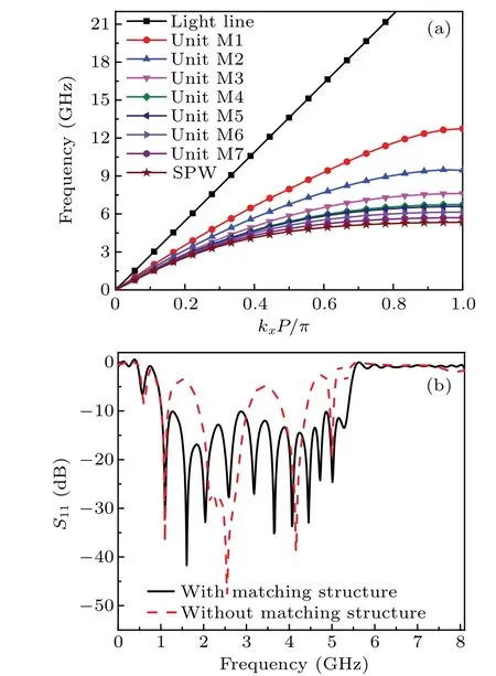
Fig.4. (a)The evolution of the normalized wave vector of different units in Part II and Part III.(b)The simulated S11 of the UWB SSPPs BPF with and without transition structure.
To further comprehend the filtering distinction,the simulated near-field distributions of thez-component electric field on thex-yplane of the proposed SSPPs BPF are plotted in Figs. 5(a)-5(d) at (a) 4 GHz, (b) 5 GHz, (c) 6 GHz, and (d)8 GHz, respectively. As shown in Figs. 5(a) and 5(b), the guided waves in the slotline waveguide are gradually transformed to SSPPs waves,and SSPPs waves can be transmitted efficiently, for example, at 4 GHz and 5 GHz. However, the waves can be coupled to the slotline waveguide through the microstrip feeding-line. Still, it is in the cutoff frequency region of the L-shape fold grooves SSPPs structure at 6 GHz and 8 GHz,so it cannot be transmitted through the SSPPs waveguide,as displayed in Figs.5(c)and 5(d).

Fig.5.The near-field distribution of the z-component electric field on the x-y plane above the top surface of the proposed SSPPs BPF at(a)4,(b)5,(c)6,and(d)8(in unit GHz).
To get an insight into the strong confinement characteristics, the simulated electric field amplitudes of the proposed BPF at different frequencies along theydirection in the crosssection A-A′and along thezdirection,as shown in Figs.6(a)and 6(b),respectively. It can be seen that the electric field amplitude is the largest at the center point and decreases rapidly in the direction perpendicular to the propagation direction. As shown in Fig.6(b),the proposed L-shape fold slotline SSPPs waveguide has solid electric field confinement on the surface,and the electric field amplitude attenuates rapidly in the free space along thezdirection at 4 GHz. The insets of Fig. 6 show the power distribution of the BPF on the cross-sectionyozplane at different frequencies of 4 GHz and 6 GHz. These two illustrations show a field distribution and intensity similar to that in Fig.5. Therefore,the designed compact SSPPs slot waveguide structure offers strong confinement performance.

Fig.6. The electric field amplitude distributions|E|of the designed at different frequencies: (a)along the y direction in the cross-section AA′,(b)along the z direction. The insets show the power distributions at 4 GHz and 6 GHz.

Fig. 7. (a) Dispersion curves of the fundamental modes for the SSPPs unit cell with various values d. (b)The simulated S21 for the SSPPs BPF varied the length of the branch slot line parallel to the central slotline d.
To investigate the influence of the branch slot line parallel to the central slotline on the transmission characteristics of the proposed BPF,we first analyze dispersion curves of the fundamental modes for the SSPPs units with various lengths valuesd,as shown in Fig.7(a). Thedvaries from 1.5 mm to 3.0 mm at intervals of 0.5 mm withh=2,s=0.2,a=1.2,w=0.2,b=1,P=4(in unit mm),andN=5. As can be seen in Fig. 7(a), when the lengthsdof the branch slot line parallel to the central slotline increase,the asymptote frequency is decreased. Figure 7(b) shows the transmission performance of the SSPPs BPF with varied length of thed. Obviously,the upper cutoff frequency edge of the passband shifts downward when the lengths ofdincrease,which is consistent with Fig. 7(a). Therefore, it can be concluded that the length of the branch slot line parallel to the central slotline is negatively correlated with the asymptotic frequency, and the longer the length,the stronger the EM confinement.
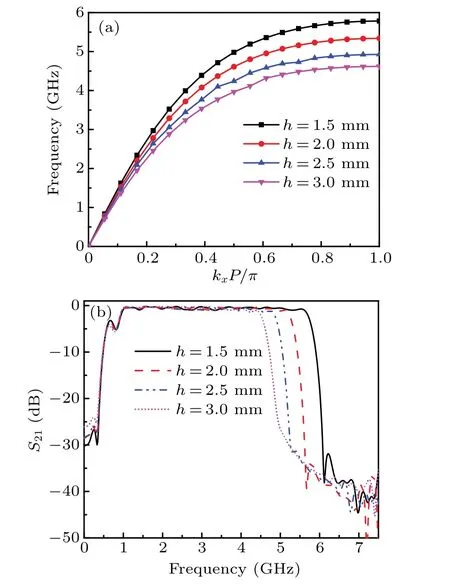
Fig. 8. (a) Dispersion curves of the fundamental modes for the SSPPs unit cell with various h. (b) The simulated S21 for the SSPPs BPF varied the height of the L-shape groove h.
Next, we analyze the impact of different depths of the grooves on transmission characteristics of the proposed SSPPs BPF. Figure 8(a) shows the dispersion curves of the type-C units with various valuesh. Thehvaries from 1.5 mm to 3.0 mm at intervals of 0.5 mm withd=2,s=0.2,a=1.2,w=0.2,b=1,P=4 (in unit mm), andN=5. As can be seen in Fig. 8(a), the asymptote frequency decreases of the SSPPs unit with the increase of grooves depthhfrom 1.5 mm to 3.0 mm at intervals of 0.5 mm. Figure 8(b)shows the transmission performance of the SSPPs BPF with varied the length of theh. It can be seen that with an increase in the depth of the grooves, the upper-frequency edge of the passband has a tardily redshift,and the lower frequency edge of the passband remains unchanged.
Furthermore,the effects of the different widths of the slotline on transmission characteristics of the SSPPs BPF are investigated. Figure 9(a) shows the dispersion curves of the type-C units with various width values of the fold slotline.Thesvaries from 0.1 mm to 0.4 mm at intervals of 0.1 mm withd=2,h=2,a=1.2,w=0.2,b=1,P=4 (in unit mm),andN=5. In Fig. 9(a), it can be seen that with an increase in the width of the slotline, the asymptote frequency increase of the proposed SSPPs unit (type-C). Figure 9(b) shows the simulatedS21for the SSPPs BPF with the widthsvaried from 0.1 mm to 0.4 mm at intervals of 0.1 mm.The upper-frequency edge of the passband has a slightly blue shift as the width ofsincreases,as shown in Fig.9(b).
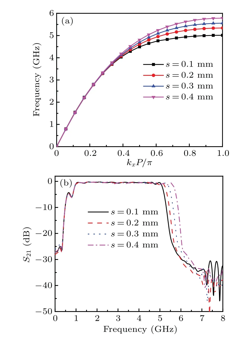
Fig.9. (a)Dispersion curves of the type-C units with various values s. (b)The simulated S21 for the SSPPs BPF varied the width of the groove s.
In addition, the effects ofN-cascaded SSPPs units of the slotline on transmission characteristics of the proposed SSPPs BPF are investigated. Figure 10 shows the simulated S-parameters of the SSPPs UWB BPF with the variance of the number of SSPPs unit cellsN. The transmission performance of the proposed SSPPs BPF in the passband have a negligible effect as the number ofN-cascaded SSPPs units, which manifests the number ofN-cascaded SSPPs units is insensitive to the surface wave propagation, as shown in Fig. 10(a).Figure 10(b)illustrates the comparison of simulatedS11of the proposed BPF with differentN(N=3, 5, 7, 9), in which theS11exhibits little difference. The results show that the insertion loss of the slotline SSPPs waveguide is very minute, in other words, the high-efficiency propagation of the proposed BPF can be achieved.
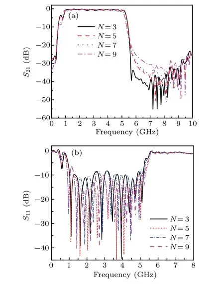
Fig.10. The simulated S-parameters of the SSPPs UWB BPF with the variance of the number of SSPPs unit cells N: (a)S21,(b)S11.
4. Experimental results
A prototype with a size of 108 mm×16 mm,is fabricated and measured to validate the SSPPs BPF.Figure 11 shows the fabricated sample of the proposed SSPPs BPF. The optimal dimension parameters are:s= 0.2,a= 1.2,b= 1,d= 2,w=0.2,h=2,P=4(in unit mm), andN=5. Using coaxial connector as input and output of microwave signal. Then the BPF prototype was measured by vector network analyzer of Agilent N5245A. Figure 12 shows the measured and simulatedS-parameters of the novel SSPPs BPF. The passband of the measured results and the upper-frequency edge of the passband about 5.3 GHz are roughly coincident with simulated. As shown in Fig. 12, the measured 3-dB bandwidth of 142% with the center frequency at 3.05 GHz, and the insertion loss of average in the passband is 0.5 dB. Figure 13 shows the measured group delay of the fabricated sample from 1 GHz to 5.5 GHz. The group delay fluctuates and increases with the frequency increases, which is always a tradeoff between the high-frequency rejection in the passband edge of theS21and phase linearity. The measured results verify the highefficiency filtering performance of the proposed structure.
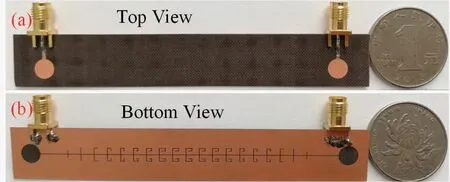
Fig.11. Photographs of the fabricated sample: (a)top view,(b)bottom view.

Fig. 12. Measured and simulated S-parameters of the novel ultra-wideband SSPPs bandpass filter.

Fig.13.The measured group delay of the passband for the UWB SSPPs BPF.

Table 1. Comparison of the proposed filter and other SSPPs filters.
To highlight the advantages of the proposed highconfinement UWB plasmonic bandpass filter, Table 1 lists the coplanar waveguide and quasi-SSPPs structure,[28]the ultrathin metallic SSPPs structure,[32]the coplanar stripline plasmonic waveguide,[33]the half-mode substrate integrated waveguide (HMSIW) filters,[34,35]the dumbbell grooves UWB filter,[36]the slotline SPP differential filter,[38]and the proposed filter, in which the FWB, IL, RL, andλ0represent the fractional bandwidth, insertion loss, return loss, and the wavelength corresponding to the central operating frequency,respectively. The comparison shows that the proposed plasmonic bandpass filter has the superior performance in miniaturized electrical size and broad bandwidth.
5. Conclusion
In this paper,a novel SSPPs BPF is proposed,composed of slotline waveguide-loaded L-shaped branch grooves. Compared with the traditional rectangle slotline waveguide, the proposed novel structure realizes high-efficiency transmission,miniaturization,and strong field confinement at the same size.The dispersion characteristics and transmission properties of the proposed BPF are numerically analyzed by using FDTD.The results show that the dispersion curve of the proposed SSPPs unit has a lower asymptotic frequency, and the transmission characteristic of the novel SSPPs BPF can be tunable by changing the branch groove. To validate the design concept, the prototype of the BPF has been manufactured and measured. The experimental results of the fabricated sample agree with the numerical simulation results well. The proposed novel SSPPs waveguide not only makes the design of slot waveguide more diversification, but also provides a good reference value for the application of high-performance,strong field confinement,and miniaturized plasmonic devices in the microwave and THz bands.
Acknowledgements
Project supported by the National Natural Science Foundation of China (Grant Nos. 62071221 and 62071442), the Equipment Advance Research Foundation of China (Grant No.80909010302),and the Key Laboratory of Radar Imaging and Microwave Photonics (Nanjing University of Aeronautics and Astronautics),Ministry of Education of China(Grant No.NJ20210006).
杂志排行

Chinese Physics B的其它文章
- Superconductivity in octagraphene
- Soliton molecules and asymmetric solitons of the extended Lax equation via velocity resonance
- Theoretical study of(e,2e)triple differential cross sections of pyrimidine and tetrahydrofurfuryl alcohol molecules using multi-center distorted-wave method
- Protection of entanglement between two V-atoms in a multi-cavity coupling system
- Semi-quantum private comparison protocol of size relation with d-dimensional GHZ states
- Probing the magnetization switching with in-plane magnetic anisotropy through field-modified magnetoresistance measurement