Plasmonic sensor with self-reference capability based on functional layer film composed of Au/Si gratings
2022-01-23JiankaiZhu朱剑凯XiangxianWang王向贤YunpingQi祁云平andJianliYu余建立
Jiankai Zhu(朱剑凯) Xiangxian Wang(王向贤) Yunping Qi(祁云平) and Jianli Yu(余建立)
1School of Science,Lanzhou University of Technology,Lanzhou 730050,China
2College of Physics and Electronic Engineering,Northwest Normal University,Lanzhou 730070,China
3School of Electronic Engineering,Chaohu University,Chaohu 238000,China
Keywords: self-reference,plasmonic sensor,functional layer,sensitivity
1. Introduction
Nanotechnology is one of the most attractive and important technologies in the twenty-first century. Due to its wide application in fields such as photocatalysis,[1-3]photonic crystals,[4,5]polarization conversion,[6,7]absorption enhancement,[8,9]and so on,[10-12]it has attracted a great deal of research attention over the past two decades. In the field of micro-nano optics,surface plasmon polaritons(SPPs)play an important role in optical device integration, as they can confine electromagnetic waves at the nanoscale.[13]SPPs are excited by external electromagnetic waves and are formed by the collective oscillation resonance coupling of photons and free electrons on a metal surface. In general, surface plasmons(SPs)can be divided into propagating surface plasmons(PSPs)that propagate on flat metal surfaces and localized surface plasmons(LSPs) that use various metal nanoparticles as carriers.[14]The two kinds of SP can be used in different fields,according to their different excitation mechanisms and action characteristics. For example, PSPs with a typical penetration depth of 200 nm excited by prisms and gratings can be used in plasmonic photolithography,[15]while LSPs directly excited on nano-metal particles with a typical penetration depth of 50 nm can be used in surface-enhanced Raman scattering.[16]
Resonance-based structures are generally attractive in the field of sensors, as the resonance position (angle or wavelength) is usually easy to detect, and in most cases, surface plasmon resonance(SPR)is very sensitive to changes in analyte environments.[17-23]In the context of refractive index(RI)sensing,external environmental factors,such as optomechanical drifts and temperature changes,decrease the sensing accuracy and correctness of SPR-based sensors.[24-27]Therefore,it is useful to develop RI sensors with multiple signal channels to eliminate the influence of external environmental factors.In 2017,Wanget al.experimentally demonstrated a plasmonic structure that could excite double Fano resonances for self-reference RI sensing.[25]Using a reference signal whose resonance wavelength does not change with the analyte’s RI,the influences of light intensity fluctuations and local temperature variations can be eliminated. The sensitivity and figure of merit (FOM) of the sensor are 470 nm/RIU and 31 RIU-1,respectively. In 2020, Kohandaniet al.used metallic arrays(two-dimensional Au gratings)to achieve optical momentum matching,[27]exciting multiple resonance modes including LSPs and Fabry-Perot modes in the structure and realizing a self-reference ability with an RI sensitivity of 429 nm/RIU.Although plasmonic RI sensors with a self-reference capability can overcome environmental errors to a certain extent,the sensing performance is reduced because of the inevitable impact of the reference channel on the structural optimization.
In a previous work, we achieved high-sensitivity RI sensing through a novel Au/Si complementary grating structure.[28]However, its self-reference characteristics were not been explored. In this work, we further expand the application range of the structure by realizing the self-reference function during the RI sensing process. We show, based on theoretical analysis and numerical simulation, how the complementary grating structure can excite high-quality SPPs on the upper and lower surfaces of the flat functional layer under normal incidence conditions. Also, numerical simulation results show that multiple SPRs have different origins and are independent of each other. The SPRs excited on the upper surface of the functional layer are sensitive to RI changes of the environmental analyte, while the SPRs excited on the lower surface are sensitive to RI changes of the substrate material. As a major result, good self-reference characteristics can be implemented in the complementary grating structure.The sensing performance analyses mainly revolve around the self-reference characteristics that can be achieved.
2. Sensing structure and theoretical analysis
A schematic of the designed complementary grating structure is shown in Fig. 1(a). The structure is twodimensional,sincezis assumed to be invariant outside thexyplane, which can be realized in practice with appropriately wide functional-layer slabs (e.g., complementary Au/Si gratings).In actual RI sensing,the components of the system from top to bottom are an infinitely thick analyte environment, the Si grating,the Au grating,and a substrate with good adhesion to the functional layer. However, the positions of the analyte and the substrate are interchangeable, since SPRs can be excited on both surfaces of the functional layer(as discussed below). The enlarged details of the structure show the main geometric parameters,which are the widthwand depthdof the slit in the Au grating and the thicknessest1andt2in the complementary grating.The selected periods of the Au/Si gratings produce SPR wavelengths in the near-infrared communication window. For light sources and detectors integrated with optical fibers, this spectral range is relatively easy to obtain and can be used for applications such as online monitoring and remote sensing. This geometric structure can be easily fabricated with a large area to achieve low costs through existing mature micro-nano manufacturing processes such as electron beam lithography(EBL)and reactive ion etching(RIE).

Fig.1. Cross-sectional illustration of the plasmonic RI sensor based on complementary Au/Si gratings. The contents of the dotted circle show the main geometric parameters. The propagation and polarization directions of the radiated light are indicated by black and blue arrows,respectively.
In the proposed structure,light scattering(subwavelength diffraction) caused by normal incidence is contributed by the one-dimensional Au grating in the functional layer.The resulting diffracted light series at different angles can be expressed as
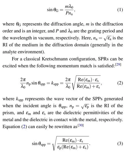
In the designed grating-coupled sensing system,nacan be regarded as equal tonpin the Kretschmann configuration. Thus,the momentum matching condition on the lower surface of the functional layer is satisfied when sinθG= sinθspp; then, by combining Eqs.(1)and(3),we get

Equation(4)is helpful for predicting the SPR wavelength and guiding the design of the grating period.Using the same mechanism, SPPs can also be excited on the upper surface of the functional layer. In the SPR modes characterized by reflection spectra,the magnitudes of the reflectivities are related to the intensities of the resonances,which are determined by the coupling efficiency of the grating.
3. Results and discussion
The finite-difference time-domain method is used to extract the electric field distributions and the reflection spectra used to complete the plasmonic response analysis and the characterization of the RI sensing performance. In the following simulations, a single unit cell is selected for numerical calculations due to the periodicity of the structure. The optical constants of Au and Si are dispersive and obtained from experimental data.[31,32]
3.1. Plasmonic responses
Figure 2(a) shows the reflection spectra of the structure when the grating periods are changed from 1200 nm to 1400 nm at 40 nm intervals. For the convenience of analysis, the RIs of the analyte and the substrate are assumed to be 1.00 and 1.40, respectively, and the geometric parameters of the structure arew=400 nm,d=110 nm,t1=30 nm,andt2=20 nm. As shown in Fig. 2(a), the structure excites three SPR modes in the near-infrared band, labeled mode 1,mode 2, and mode 3. Mode 1 is potentially suitable for RI sensing because of its strong resonance intensity and simultaneous narrow full width at half maximum (FWHM). The FWHM of mode 2 is also quite narrow;the resonance intensity of mode 3 is strong but its FWHM is very wide. Importantly,it can also be observed from Fig.2(a)that the resonance wavelengths of modes 1 and 2 show redshifts as the grating period uniformly increases. It can be inferred that these two modes are due to SPRs excited on the upper and lower surfaces of the functional-layer film caused by the grating diffraction. Besides, exciting SPR on the lower surface inevitably requires diffractive light to penetrate the functional-layer film. Accordingly, mode 2, whose resonance intensity is weaker than that of mode 1, propagates on the lower surface of the functional layer.
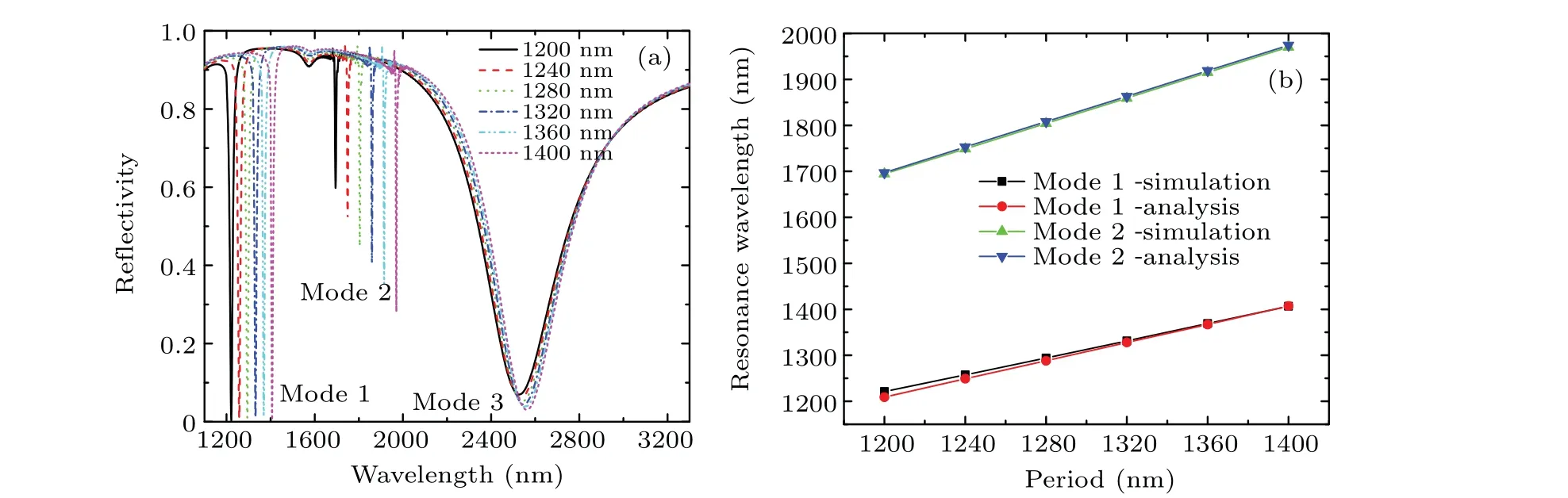
Fig. 2. (a) Reflectance spectra of the designed structure in the near-infrared band for different grating periods. (b) Comparison between the theoretical calculation and the numerical simulation of the resonance wavelengths of SPPs.

Fig.3. The electric field distributions at the resonance wavelengths of modes 1,2,and 3(geometric parameters correspond to Fig.2(a)with the grating period of 1400 nm). The total electric field distributions(E/Ein)2 of(a)mode 1,(b)mode 2,and(c)mode 3. The x-component electric field distributions(Ex/Ein)2 of(d)mode 1,(e)mode 2,and(f)mode 3. The y-component electric field distributions(Ey/Ein)2 of(g)mode 1,(h)mode 2,and(i)mode 3.
The resonance wavelengths of SPPs calculated by Eq.(4)prove the correctness of the above qualitative analysis of modes 1 and 2. Figure 2(b) shows the results of a comparison between the resonance wavelengths obtained by numerical simulation and those obtained by theoretical calculation. It can be seen that the theoretical calculation of mode 2 is in good agreement with the numerical simulation,while there are some errors for mode 1. The reason for this is that mode 2 is excited on the lower surface of the functional layer where the Au grating is in direct contact with the substrate, while mode 1, excited on the upper surface, does not consider the influence of the Si grating in the theoretical calculation. Nevertheless,the Si grating is important in our structural design,because it can not only protect the Au grating that plays a major role in subwavelength diffraction,but also cause the energy of the excited SPP to couple more uniformly to the analyte environment.[28]The error in the mode 2 result is considered acceptable.
Electric field distributions help us to intuitively understand the formation mechanism of SPRs. Figure 3 shows the electric field distribution in each mode corresponding to the geometric parameters of Fig. 2(a) with a grating period of 1400 nm. Figures 3(a), 3(d), and 3(g) show the total electric field distribution,x-component electric field distribution,andy-component electric field distribution of mode 1,respectively. Similarly,Figs.3(b),3(e),and 3(h)correspond to mode 2 and Figs. 3(c), 3(f), and 3(i) correspond to mode 3. From Fig.3(b), we can observe the typical characteristics of a PSP excited by a first-order grating coupling,which are manifested in the confinement of the field energy to the metal surface and rapid decays in the normal direction. The electric field energy of mode 2, which is mainly in theydirection, proves that the PSP propagates in thexdirection. An identical resonance mechanism occurs on the upper surface of the functional layer (mode 1). The designed plasmonic structure can generate high-quality SPPs on the upper and lower surfaces of the functional layer. We believe that this plasmonic structure is fundamentally interesting and can be used in other fields,since the flat upper and lower surfaces of the functional layer provide a lot of space for regulating SPPs.The main reason for the formation of mode 3 is the lateral oscillation(x-direction)of free electrons in the Au grating bars. The analysis results of the electric field distributions are consistent with those of the reflection spectra.
3.2. The self-reference sensing performance of the structure
Based on the above detailed plasmonic response analysis,the following discussions focus on the sensing performance of the structure with self-reference characteristics. In the field of plasmonic RI sensing,two physical parameters are used to quantify the sensing capabilities. The sensitivity is defined as

where Δλis the resonance wavelength shift corresponding to the change per unit of RI of analyte Δn. A figure of merit(FOM)is used to describe the influence of the FWHM on the sensing performance,which can be defined as

The FOM is an important indicator for the sensing accuracy of plasmonic RI sensors.
Figure 4(a)shows the reflectance spectra of the structure when the analyte’s RI changes from 1.00 to 1.10 at intervals of 0.02. Here, the geometric parameters arew= 400 nm,d= 110 nm,t1= 30 nm,t2= 20 nm,P= 1320 nm, and the substrate material is silica. As can be seen, in the case of Fig. 4(a), the resonance wavelengths of strong modes 1 and 3 are redshifted with a steady increase of the analyte’s RI.The wider interaction range between mode 1 and the analyte explains the larger resonance drift, compared with mode 3. Also, the spectrum profile of mode 1 is clear and recognizable under different analyte RIs, which is a benefit of the narrow FWHM. Mode 1 is responsible for the RI sensing in this structure. More importantly, mode 2 is completely insensitive to changes in the analyte RI, with the result that it can achieve self-reference characteristics. One problem with plasmonic sensors is that they are concurrently sensitive to external influence factors, such as fluctuations in temperature and incident light intensity. If another resonance mode can be introduced into the sensing process, and the signal of this resonance mode is weakly affected by changes in the analyte environment,then this resonance mode can be used as a selfreference. Through the reference signal,it is possible to determine whether signal changes originate from the analyte environment,and drift errors of the sensing signal can be compensated to a certain extent,which can largely guarantee the sensing accuracy. The almost complete lack of interaction with the analyte environment results in the excellent self-reference characteristics of mode 2. Figure 4(b) shows the resonance wavelength and FOM of mode 1 for different analyte RIs corresponding to Fig.4(a). The good linear relationship between the resonance wavelength and the analyte RI stabilizes the sensitivity at a constant high value of 1236 nm/RIU(according to Eq. (5)). In the analyte RI range of 1.00 to 1.10, the FOM exceeds 100 RIU-1and its maximum can reach 145 RIU-1.In this RI range, the structure can realize the RI sensing of a mixed gas whose RI is related to the mix ratio. Table 1 shows a comparative analysis of the sensing performance of the complementary grating structure and different nanostructures used for self-referential RI sensing, which reflects the sensitivity advantage of our structure.

Fig.4. (a)Reflection spectra for analyte RIs varying from 1.00 to 1.10 at intervals of 0.02;the inset shows the spectral details corresponding to the red dashed box. (b)Resonance wavelength and FOM as functions of the analyte RI(mode 1);the inset shows the FWHM of mode 1 for various analyte RIs.

Table 1. Comparison with earlier reported works based on dielectric/metal gratings.
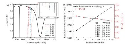
Fig.5. (a)Reflection spectra with substrate RIs varying from 1.34 to 1.44 at intervals of 0.02;the inset shows spectral details corresponding to the red dashed box. (b)Resonance wavelength and FOM as functions of the substrate RI(mode 2);the inset shows the FWHM of mode 2 for different substrate RIs.
In order to comprehensively understand the self-reference characteristics of the structure, the reflection spectra of the structure are shown in Fig. 5(a) for different substrate RIs(1.34 to 1.44 at intervals of 0.02). Here,the geometric parameters arew=400 nm,d=110 nm,t1=25 nm,t2=20 nm,P=1400 nm, and the analyte RI is equal to 1. It can be observed that as the substrate’s RI steadily increases, the resonance wavelength of mode 2 is redshifted,while modes 1 and 3 remain unchanged. The electric field distributions in Fig.3 explain this phenomenon well. Figure 5(a) guides the design of the reference signal,that is,wave domain control of the reference signal can be achieved by selecting an appropriate substrate material. Figure 5(a)also provides another way for the structure to be used for RI sensing. By exchanging the positions of the analyte environment and the substrate material,RI sensing of structures in the liquid range can be realized,for example,glycerin-water solutions of different concentrations at room temperature.[33]To illustrate this point,Fig.5(b)shows the sensitivity curve of mode 2 and the variation of its FOM trend corresponding to Fig.5(a). The sensitivity is calculated to be 1387 nm/RIU and its FOM can be as high as 368 RIU-1when the analyte’s RI is close to that of liquid. Also,the structure does not lose the self-reference characteristic, since, in this case,modes 1 and 3 can be used as reference signals.
4. Conclusion
In summary,we have realized plasmonic RI sensing with good self-reference characteristics in a simple system composed of Au/Si complementary gratings. The simulation results, which are consistent with the theoretical analysis, fully prove that two high-quality PSPs are excited on the upper and lower surfaces of the functional layer, respectively. The PSP excited on the side of the substrate achieves good selfreference characteristics, since it has almost no reaction with the analyte environment. Also, the analyte environment and the substrate material can exchange positions,which is a benefit of the propagation characteristics of the SPP in this system.A remarkable high sensitivity of 1236 nm/RIU is achieved with high accuracy for an analyte RI range of 1.00 to 1.10.Its simple geometry, high sensitivity, and good self-reference characteristics make this sensor suitable for widespread use in the field of biochemistry.
Acknowledgement
Project supported by the National Natural Science Foundation of China(Grant No.61865008).
杂志排行

Chinese Physics B的其它文章
- Superconductivity in octagraphene
- Soliton molecules and asymmetric solitons of the extended Lax equation via velocity resonance
- Theoretical study of(e,2e)triple differential cross sections of pyrimidine and tetrahydrofurfuryl alcohol molecules using multi-center distorted-wave method
- Protection of entanglement between two V-atoms in a multi-cavity coupling system
- Semi-quantum private comparison protocol of size relation with d-dimensional GHZ states
- Probing the magnetization switching with in-plane magnetic anisotropy through field-modified magnetoresistance measurement