Dynamic control for the feed system of a robotic drilling end-effector①
2022-01-09ZhangLaixi张来喜ZhaoChenmingWuMingliang
Zhang Laixi(张来喜),Zhao Chenming,Wu Mingliang
(School of Mechanical and Electronical Engineering,Lanzhou University of Technology,Lanzhou 730050,P.R.China)
Abstract
Key words:robotic drilling,feeding system,pole-placement,model reference adaptive
0 Introduction
Since robot has been successfully implemented in automotive industry,robotic drilling system has been intriguing more and more research interest in aero structure assembly[1].With the rapid development of robotic technology of high positional accuracy,payload capability and stiffness and position compensation,and the robotic advantage of low cost and high flexibility,robot has been becoming an effective base platform for robotic drilling system[2-3].Zhang and Jiang[4]designed a mobile automated robotic drilling system used for wing assembly with AGV carrying robot.Liu et al.[5]developed an automatic drilling and riveting system for aircraft panel assembly adopting two cooperative machines.The drilling end-effector is a key sub-system for robotic drilling system to meet high performance expectations and low-cost demands.Devlieg[6]developed a servo-controlled multifunction drilling end-effector named ONCE end-effector to drill,countersink,and measure fastener holes in the wing trailing edge flaps on the Boeing F/A-18E/F Super Hornet.Webb et al.[7]developed a compact and innovative end-effector which is capable of performing drilling,countersinking,sealing and riveting operations and also containing a significant amount of process monitoring sensors to enable automated in-process checks and quality measurement.Liang and Bi[8]developed a drill end-effector for use on industrial robots.The real-time force feedback can detect dull or broken bits,drilling breakthrough,and plot thrust force while drilling.Chen et al.[9]proposed a method of predicting the clamping force for robotic drilling end-effector.Generally,a drilling end-effector consists of support cell,spindle cell,posture adjusting cell,compressing cell and feeding cell.The feeding motion(involving feeding speed and feeding force)has significant impact on the drilling precision.Li et al.[10]developed a method to suppress the surface contact slipping by keeping the drilling tool normal with the workpiece surface through three force sensors.Zhang et al.[11]analyzed the impact of the stiffness properties,the preload force and the accuracy of the robot,the matching criterion of robot drilling posture and thrust force is proposed.A multi-functional robotic drilling end-effector was designed for assembling components of specific materials such as carbon fiber reinforced polymer and aluminum[12].Several online detection and adjustment methods are applied to this end-effector to achieve higher accuracy of the drilling.However,these efforts focus mostly on integrating multifunctional end-effector design,positioning and calibration method development and static accuracy ensuring,kinematics of the normal adjustment,and few studies have been investigated in regard to dynamic model and control of the feeding system.Though Garnier et al.[13]modeled robotic drilling with two methods focused on the cutting process where the chip section was discretized and computed at each step and took into account the stiffness of the robot at hand,the feeding dynamics was not involved.This paper proposes a dynamic model for the feeding unit of the robotic drilling system,and two control algorithms are developed and compared as well.
This paper is organized as follows.Section 1 describes the dynamical model for the feed unit of the designed robotic drilling end-effector.The state feedback controller is presented in Section 2.The model reference adaptive controller is proposed in Section 3.The tracking performance of the feed unit with the proposed controller is demonstrated in Section 4.The conclusions are presented in Section 5.
1 Dynamical model for the feed unit
A robotic drilling end-effector is developed;a diagram and a photograph of the system are shown in Fig.1.The main functions of the proposed robotic drilling end-effector include:measuring and calculating the outward normal of the fuselage skin surface at drilling point,adjusting spindle axis to coincide with the normal and drilling after the skin is reliably compressed.Two axes which are perpendicular to each other are installed in the same plane.The spindle can rotate about these two axes,thus completing the spindle normalization.
The feed unit of the robotic drilling end-effector is composed of a servo motor,a ball screw pairs,a sliding platform and a spindle,and the spindle is fastened on the sliding platform.The ball screw is driven by the servo motor and transforms the rotational motion of the motor into the feed motion of the spindle.Fig.2 shows the structure of the feed unit.
The dynamic equation can be derived from Fig.2 as following forms.
whereJis moment of inertia of the ball screw and the motor;θis motor rotation angle;B1is frictional damping coefficient of the screw;Tdis ball screw load torque;τis the driving torque of the servo motor,it is also the control variable;mis platform mass;xis platform displacement;B2is frictional damping coefficient of platform;Flis load force andFtis disturbance force;Fdis driving force acting on platform;kis transform coefficient,andk=p/(2πζ),in whichpdenotes ball screw lead andζdenotes conversion efficiency;it can be also hadθ=2πx/pand

Fig.1 The designed robotic drilling end-effector
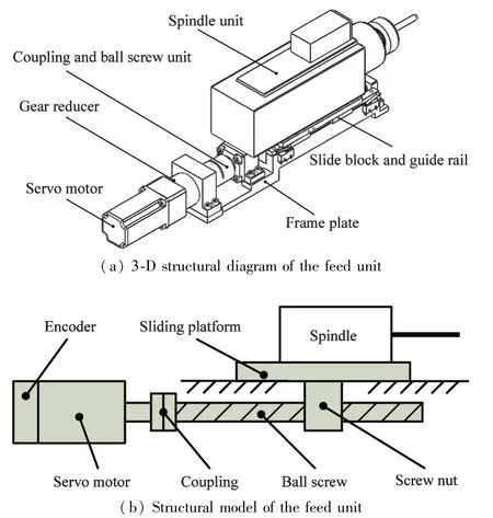
Fig.2 The structure of the feed unit

The dynamic equation can be considered as
Eq.(2)can be rewritten as

whereMdenotes equivalent mass;Bdenotes equivalent damping coefficient;τfdenotes equivalent linear frictional torque;τwdenotes equivalent nonlinear frictional torque and disturbance.And the linear frictional torque is simplified as a constant with the same direction with the platform speed.
Eq.(3)did not take into consideration the dynamic characteristic of the motor,and the motor was driven in speed mode during experiment.In order to develop the controller,the dynamic characteristic of the servo driver including the embedded speed controller along with the mechanical part of the feed unit should be take into account.By using laser interferometers to measure the platform speed,the system model was identified based on step response.Unit step inputs of 1vand 2vhave been added on system,the speed step responses of 1vand 2vare shown in Fig.3(a)and(b),respectively.As can be seen from the diagram,when the servo driver runs in speed mode,the system

Fig.3 Unit step response of the feed unit
with the servo driver exhibits the characteristic of a second-order system and presents nearly the same performance on different input signals.
On the basis of the speed step response curve and the dynamic performance index,the speed transfer function of the system can be calculated as
The position transfer function can be expressed as
2 State feedback control based on pole placement
2.1 Pole placement of state feedback
The state space description is built from Eq.(5)as

where
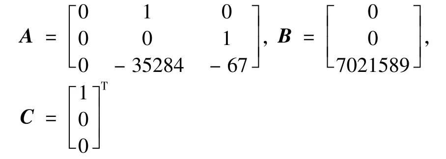
In order to analyze the controllability of the system,ABandA2Bmust be calculated.
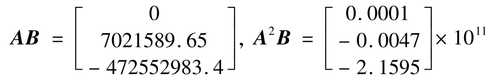
It can be calculated that rankM=rank[BABA2B]=3,thus the system is controllable.
SetK=[k1k2k3]as state feedback gain matrix.And by using the linear state feedback,the system state equation is rewritten as

The close-loop system will be designed to satisfy the following performance indicators.
(1)The maximum overshoot isσ%≤5%;
(2)The adjustment time ists≤0.02s;
(3)The steady state error of unit step response is 0.


Using Ackerman formula,it can be calculated as
K=[5.0479 0.0337 0.0001]
2.2 Pole assignment controller based on reducedorder state observer
The speed and acceleration of the platform must be known for the feedback signals of the system.Theoretically,speed signal can be acquired by taking the first-order derivative of the displacement signal and performing filter.And acceleration signal can be obtained by taking the second-order derivative of the displacement signal and performing filtering.However,the signal after being filtered is time-lagged,which will affect the control precision and even cause system distortion and instability.Aiming at this problem,a reduced-order state observer is presented to observe the unmeasurable speed and acceleration signal.
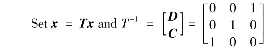
Then
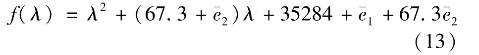
The desired characteristic polynomial of the reduce-order state observer is constructed as

Set the feedback matrix of reduce-order state observer as

The characteristic polynomial of the reduce-order state observer is explained as

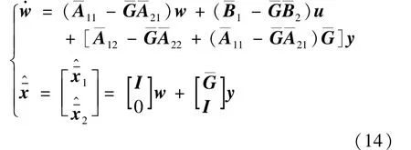
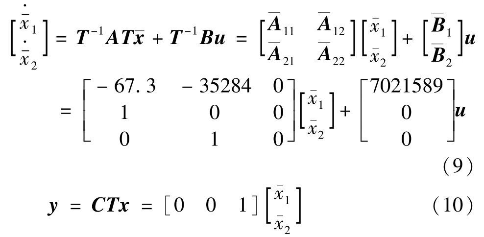
Substituting Eqs(9)and(12)into Eq.(14),it can be yielded as
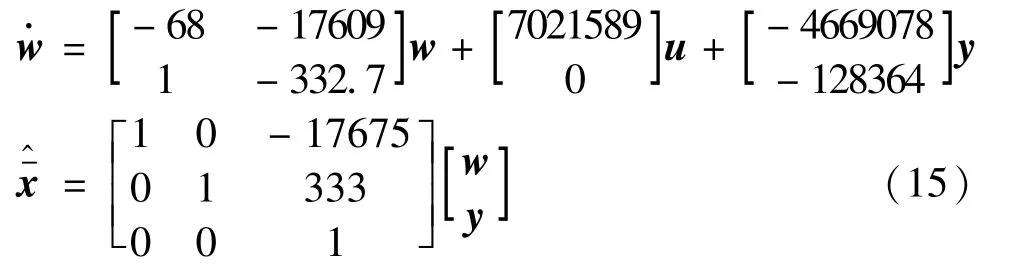
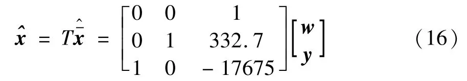
The estimate of system state vector can be calculated as
Combining pole assignment with reduce-order state observer,the control diagram is shown as Fig.4.

Fig.4 Structure of pole placement feedback controller
3 Model reference adaptive control
3.1 Reference model construction
If the nonlinear friction factor of Eq.(3)is ignored,the feed unit can be described as a second-order system with a relative order of 2.The step response of the reference model should satisfy the following dynamic characteristic indicators.
(1)Maximum overshoot isσ%≤5%;
(2)Adjusting time ists≤0.01s;
(3)The steady-state output error is 0.
The reference model is given as

3.2 Model reference controller
The block diagram of adaptive method of the second-order system is shown in Fig.5,whereP(s)denotes controlled object;c0,c1,d0,d1are tunable parameters;bλ/(s+λ)is a linear filter.

Fig.5 Adaptive method of the second-order system
Given the requirement of the reference model and the model reference adaptive controller design method,M(s)must be strictly positive real and stable minimum phase system,but the system with relative order of 2 doesn’t satisfy this condition.However,letL(s)=s+abe multiplied byM(s),N(s)=M(s)L(s)can satisfy the requirements of strictly positive realness only if the proper‘a’is chosen.
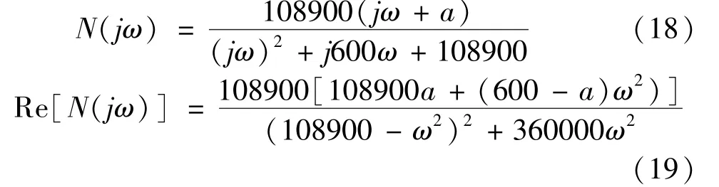
From Eq.(19)it can be calculated.When 0
In the light of the means proposed in Ref.[14],the model reference adaptive controller is designed.The structure of the model reference adaptive controller is
根据原著Donald J.Gray(2001)版本第201面的脚注释义,“to be upon the town is to engage in prostitution or thievery[3]”即“成为娼妓或窃贼”的意思。此处“upon thetown”使用了隐晦的借代修辞,“亲自上这儿来[4]”显然是误译,如果结合丽迪雅·班纳特小姐一贯轻浮浪荡的形象,将此短语译为“流落风尘”则更为合适。
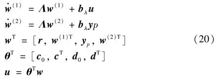
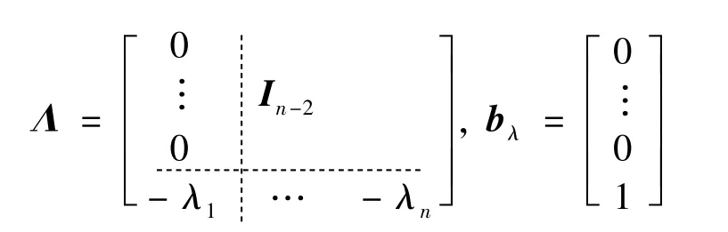
whereΛ∈R(n-1)×(n-1),bλ∈R n-1is controllable standard form.
Identifier structure is

Adaptive law(grade arithmetic)is

4 Experiment and discussion
The desired trajectory is chosen to be a sine function expressed asr=50sin(4πt).Fig.6(a)and(b)show the sinusoidal responses and the tracking of poleplacement of state feedback error respectively.
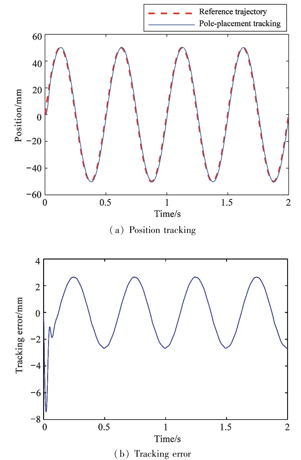
Fig.6 Sinusoidal tracking of pole-placement of state feedback
In order to further validate the dynamic performances of the model reference adaptive controller,another experiment is carried out in which the desired trajectory is set to be a same sine function asr=50 sin(4πt).Fig.7(a)shows the sinusoidal responses of the model reference adaptive control,Fig.7(b)shows the tracking error of the model reference adaptive control,and Fig.7(c)shows the tracking error of the model reference adaptive control after the adaptive process.
A short phase lag was present in trajectory tracking of pole-placement of state feedback,whilst the trajectory yielded by the model reference adaptive controller coincided with the desired trajectory and had much less error after the initial transient than the pole-placement of state feedback did.And the tracking error of the model reference adaptive controller became smaller and smaller with the adaptive process while that of the pole-placement of state feedback presented a sinusoidal wave with a constant amplitude.After the adaptive process,the tracking error of the model reference adaptive controller is much less than that of the poleplacement of state feedback.
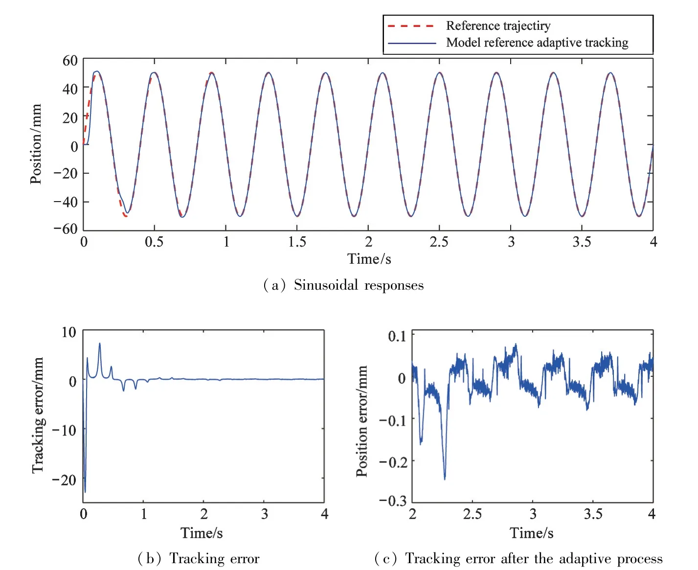
Fig.7 Sinusoidal tracking of model reference adaptive control
5 Conclusions
The model reference adaptive control system is designed based on the direct output error adaptive control algorithm,which has the advantage of being intuitive.The structure and algorithm are simple for the system with relative order of 1 or 2,but only the gradient algorithm can be used.While the relative order is larger than 2,the implementation of the system will be more complex.Moreover,the convergence rate of the adaptive gain coefficients will be slower with gradient algorithm.
The control accuracy of the model reference adaptive system after its optimization is much higher than that of the pole displacement system.For the sinusoidal input,the adaptive gain coefficients of the model reference adaptive control system converge to constants after 10 s,the position tracking error reduces to 0.1 mm from 2.8 mm of the pole displacement system after 10 s simultaneously,which is the disadvantage of the model reference adaptive control.
For sinusoidal response, the model reference adaptive controller achieved the best control effect after 1 s adaptive process.This is the disadvantage of the model reference adaptive controller. Thus, the adaptive algorithm based on direct input error and the least square will be developed in the future work to overcome the shortcoming of slow rate of convergence of the adaptive parameters.Setting the parameters after the adaptive process as the initial parameters to make the system obtain the best control effect from the initial state is another method of optimization.
杂志排行

High Technology Letters的其它文章
- On the performance of full-duplex non-orthonogal multiple access with energy harvesting over Nakagami-m fading channels①
- Research on optimization of virtual machine memory access based on NUMA architecture①
- Online prediction of EEG based on KRLST algorithm①
- Reconfigurable implementation ARP based on depth threshold in 3D-HEVC①
- Positive unlabeled named entity recognition with multi-granularity linguistic information①
- Behavior recognition algorithm based on the improved R3D and LSTM network fusion①