Single-mode antiresonant terahertz fiber based on mode coupling between core and cladding∗
2021-12-22ShuaiSun孙帅WeiShi史伟QuanSheng盛泉ShijieFu付士杰ZhongbaoYan闫忠宝ShuaiZhang张帅JunxiangZhang张钧翔ChaoduShi史朝督GuizhongZhang张贵忠andJianquanYao姚建铨
Shuai Sun(孙帅) Wei Shi(史伟) Quan Sheng(盛泉) Shijie Fu(付士杰)Zhongbao Yan(闫忠宝) Shuai Zhang(张帅) Junxiang Zhang(张钧翔)Chaodu Shi(史朝督) Guizhong Zhang(张贵忠) and Jianquan Yao(姚建铨)
1Institute of Laser and Optoelectronics,School of Precision Instrument and Optoelectronics Engineering,Tianjin University,Tianjin 300072,China
2Key Laboratory of Optoelectronic Information Science and Technology(Ministry of Education),Tianjin University,Tianjin 300072,China
Keywords: terahertz,mode coupling,single-mode fiber
1. Introduction
Terahertz (THz) waves locate between the far-infrared wave and microwave ranges of the electromagnetic spectrum.Earlier,this region used to be an academic blank,baffling researchers for decades. THz technology has developed rapidly and gained significance for the extensive research on THz radiation sources and detector devices. THz waves possess many unique properties,such as high penetrability into nonpolar materials and low photon energy, which promote nondestructive testing and bio-imaging.[1]High-performance THz waveguides are still in research, and the applications of THz waves are primarily based on the free-space optical path, which is inefficient and may import errors caused by the absorption of water vapor. To the best of our knowledge, almost all optical materials considerably absorb THz waves. The high material losses prevent the solid-core fiber from becoming an acceptable THz waveguide. However, the antiresonant fiber(ARF) guiding the light in the air core can weaken the effect from material absorption and achieve low-loss THz wave transmission.[2,3]
The shell of the cladding tube is the key factor affecting the light transmission in ARF.In ARF,the cladding tube’s shell acts like the antiresonant wall in the slab waveguide,making each cladding tube an antiresonant element.[4,5]In ARFs, for the antiresonance of cladding tubes, light is confined to the central air core. Only the material absorption loss at the surface contributes to the efficiency of the material absorption loss. In 2018,Gao[6]demonstrated a silica ARF with conjoined tube cladding for infrared waves,obtaining a transmission loss of 2 dB/km, the lowest transmission of ARF reported so far. Thus, it is expected to break the transmission limit of silica fiber by using the ARF.The separation between light and fiber material also guarantees the ARF a high laserinduced damage threshold; therefore, the ARF is suitable as the reaction cell for optically pumped gas fiber lasers.In 2010,Nampoothiri presented an optically pumped ethyne (C2H2)gas mid-infrared fiber laser utilizing the hollow-core fiber as the reaction gas cell and successfully obtained a 3.1-µm optically pumped gas fiber laser. Subsequently, several reaction gases were applied to broaden the output spectrum of the fiber laser.[7,8]In 2018, a 100-m ARF serving as the reaction cell and a mid-infrared fiber laser with an output of the magnitude of watts was achieved.[5]At present,ARF investigations focus mainly on the redesign of cladding tubes to improve fiber performance or realize special abilities such as birefringence and single mode.[9–13]
The most commonly used material for visible and infrared ARFs is fused silica, which causes significant absorption loss of THz waves.[14]A few polymer materials, such as polypropylene (PP), high-density polyethylene (HDPE),cyclic olefin copolymers (COC), and polymethyl-pentene(PMP; brand name: TPX).[15]Theoretical research indicates that with low-loss polymer material, the transmission loss of THz ARFs can be dozens of times lower than that of solidcore fibers.[16]In 2020, Islam reviewed the optimal materials, the guiding mechanisms, the fabrications, and the applications of various THz optical fibers; then confirmed that ARF could provide low-loss THz guidance and comparatively simple fabrication.[17]Outstanding mechanical properties and thermoplasticity make polymer materials a feasible selection for fabricating high-performance THz waveguides. In 2014,Ji proposed a porous microstructured THz fiber based on COC material;furthermore,a high-quality fiber preform was manufactured by the hot extrusion molding method and then drawn into fiber through a unique draw tower.[18]It can also fabricate the ARF preform using the stack-and-draw method[19,20]and the direct extrusion method.[21]Further, three-dimensional(3D) printing technology has also accelerated the realization of complex microstructured THz fibers.[22–24]
Considering the remarkable suppression of the polarization mode dispersion (PMD) and mode noise, single-mode fibers play a significant role in THz applications; however,there have been few comprehensive studies on single-mode THz ARFs. In 2015, Uebel proposed a single-mode hollowcore fiber achieved by the higher-order mode (HOM) filter.And then, they numerically and experimentally proved that the single-mode could occur when the diameter ratio of capillaries inside the central hollow core was approximately 0.68;besides, this single-mode guidance was demonstrated in all the wavelength ranges.[25]In 2016, Habib proposed a singlemode ARF based on anisotropic cladding tubes, and then the HOM suppression was significantly improved by using symmetrically distributed anisotropic cladding tubes.[9]In 2016,Yu designed and fabricated a hollow-core ARF with seven special cladding tubes,and the experimental results indicated single-mode characteristics.[26]In 2017, Edavalath proposed a single-mode ARF produced by geometrically twisting the fiber. The effective axial propagation constant of the fundamental mode increased and,simultaneously,the HOM was remarkably suppressed.[27]In 2019,Habib demonstrated that the geometrical structure and the number of antiresonant cladding tubes could strongly impact the HOM contents.[28]In 2020,Yan proposed a double-layer-cladding ARF,and by adjusting the diameters of two layers of cladding tubes,three broad-band single-polarization single-mode regions were achieved.[29]Our previous study has done a preliminary investigation on the HOM suppression of THz ARF.[30]In this study, the singlemode THz ARF is comprehensively investigated based on the mode coupling between the core and the cladding. Then we discussed the method of promoting single-mode performance.
2. Fiber design and numerical simulations
The guidance mechanism of ARF is well understood. In ARF,the thin shell of the periodic cladding tube has an inherent resonant period. When the wavelength of incident light is lying in this period, the incident light will resonate with the cladding tubes, causing ultrahigh transmission loss. On the contrary,when the wavelength of incident light is far from this resonant period, the cladding tubes will exclude the incident light coupling into the cladding. The confinement loss(CL)is the main contributor to the transmission loss of ARF; which can calculate using the formula
wherecis the velocity of light,fis the frequency of incident light,andNiis the imaginary part of the effective refractive index. In this study, the transmission characteristics of ARFs with different cladding tubes are investigated based on the finite-element-method software—COMSOL Multiphysics.
The 1.89-THz laser lies in the primary output spectrum of the optically pumped difluoromethane(CH2F2)THz laser;for this laser, the COC material has a complex refractive index of 1.531+0.00175i.[15]We proposed an ARF with round cladding tubes(R-ARF)based on COC material for this laser,and figure 1(a) presents the cross-sectional diagram of the fiber. The R-ARF is composed of six round tubes inserted inside the extramural cladding. The cladding tube’s inner and outer diameters are denoted bydandD, respectively, and its shell thickness is denoted byT. The size of the fiber core directly determines the transmission loss; thus, the diameter of the fiber core,Dcore, is maintained at 2000 µm. In the simulation, the shell thickness of extramural cladding keeps at 500 µm. The confinement loss of fundamental mode (CLF)varying withDandTis depicted in Fig.1(d). The simulation results indicate that this THz fiber has a significant antiresonant effect, which is mainly determined byT, and cladding tubes need enough size to expose the antiresonant effect. The electric field distributions of the fiber in resonant and antiresonant status,presented in Figs.1(b)and 1(c),demonstrate that when the fiber is in resonant state,light couples to a large extent with the cladding tubes and extramural cladding; however, when the fiber is in an antiresonant state, the cladding tubes operate like reflectors resisting the light coupling. WhenD=1.2 mm,CLFvarying withTis depicted as the solid curve in Fig. 1(d). It can be seen, with the increase inT, CLFexhibits a periodic change at 70 µm. CLFexhibits an increasing trend with the increase inTcaused by the material absorption in each optimal antiresonant status. When the ARF is in the first antiresonant period, the minimum CLFis about 0.1 dB/m,which is approximately 0.7 dB/m when the ARF is in the fourth antiresonant period.
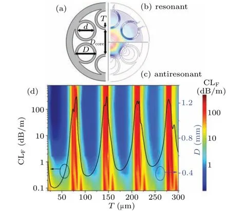
Fig.1. (a)Cross-sectional diagram of R-ARF.Electric field distribution diagrams of fibers in(b)resonant and(c)antiresonant status. (d)CLF varying with T and D. Solid curve is the CLF varying with T when D is 1.2 mm.
2.1. ARF with round cladding tubes
In the ARF with single-layer cladding tubes, investigations proved that when the ratio of the internal diameter of the cladding tubes to the core diameter is approximately 0.682:1,the HOM in the central core strongly couples with the fundamental mode (FM) in the cladding tubes, causing an abnormally high CL of the HOM(CLH).[25]In this study,the mode coupling in THz ARF has been studied thoroughly, based on the R-ARF,as presented in Fig.1(a). To facilitate the numerical calculation,Tis maintained at 104µm, leading the fiber to be in the second optimal antiresonant status. Figures 2(a)and 2(b)depict the light guidance properties of R-ARF under geometric deformation of cladding tubes. It indicates that the geometric deformation has a significant impact on HOM’s loss but barely on CLF(HE11 mode). Figures 3(a)–3(e)depict the electric field distributions of HE11 mode, TE01 mode, HE21 mode,and TE01 supermodes.
The simulation results indicate that the TE01 mode has the lowest transmission loss among the HOMs, and in this study, the TE01 mode represented the HOM. With the increase indfrom 1000 µm to 1500 µm, CLFremains almost unchanged at 0.3 dB/m; conversely, CLHappears to exhibit an abnormal growth, forming a specific suppression of the HOM in the THz wave guidance. Whendis in the range of 1320µm–1380µm,CLHis more significant than 3 dB/m,and it reaches a maximum value of 7.4 dB/m whend=1355µm.This mode coupling between the core and cladding results in suppressing the HOM; after that, the ARF can realize excellent single-mode properties. It is noteworthy that theNrof the HOM grossly decreases withd, and when the ARF is in the HOM suppression status,theNrof the HOM exhibits an abnormal variation. An ARF with dual-layer cladding tubes(duallayer ARF)and a pipe with an inner diameter ofdare proposed as control groups in this study, as illustrated in Fig.2(a), and the nested cladding tubes of dual-layer ARF can suppress the cladding mode. As the control group,this dual-layer ARF has the same geometric parameters with R-ARF;besides,the nest cladding tube has a shell thickness ofTand an inner diameter ofd/2. As indicated by the blue dotted line in Fig.2(b),in the ARF with dual-layer cladding tubes,theNrof the TE01 mode displays a linear reduction,which is the reference database for R-ARF and confirms the abnormal variation of the HOM in R-ARF.
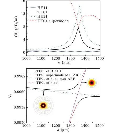
Fig.2. (a)CL of FM and HOMs varying with d in R-ARF.(b)Varying with d,the Nr of HOMs in R-ARF,and Nr of TE01 mode in dual-layer ARF,and Nr of HE11 mode in the pipe. Pipe and dual-layer ARF are illustrated.
In the simulation, when R-ARF has an apparent HOM suppression,there are two fiber TE01 supermodes,which have a relatively strong HE11 mode in the cladding and a weak TE01 mode in the core. The red dashed lines in Figs. 2(a)and 2(b), indicated the loss and theNrof TE01 supermodes.Besides, as indicated by the purple dotted–dashed line in Fig. 2(b), in the pipe,Nrof HE11 mode displays a linear growth, which is the reference database for fiber TE01 supermodes. When R-ARF approaches the optimal HOM suppression status, TE01 mode and TE01 supermode tend to be the same, distinguished as TE01 supermode(core)and TE01 supermode (cladding) based on the intensity of the mode in the cladding. The electric field distributions of the TE01 supermodes whend=1350 µm and 1360 µm are displayed in Fig.3(e),which illustrated that when the R-ARF is in the optimal HOM suppression status, the HOM in the core and FM in the cladding coexist. It can infer that there are mutual conversions of TE01 (core) and TE01 (cladding) with change ind.

Fig.3. Electric field distributions of R-ARF under different status: (a)HE11 mode,(b)TE01 mode,(c)TM01 mode,(d)HE21 mode,and(e)TE01 supermodes;arrows indicate electric field lines.
The inner diameters of the cladding tubes and central air core are varied simultaneously, and figure 4(a) depicted the CLHas a function ofDcoreandd. The peak values of CLHcorresponding to different values ofdandDcoreexhibit a linear distribution.Excluding the limited precision of the simulation calculations, the fitting curve of the peak CLHillustrates that the critical factor that determines the suppression of the HOM in the R-ARF is the rate ofdtoDcore;meanwhile,when this rate is approximately 0.677:1,the R-ARF realizes the optimal suppression of the HOM.Besides,when R-ARF realizes the optimal HOM suppression,the cross-sectional area ratio of cladding tubes and central air core is about 0.458:1. To further investigate the mode coupling between core and cladding,this paper proposed a thin-shell pipe with an internal diameter ofdand a six-close-packed-tube ARF with a core diameterD. The thin-shell pipe has the same thickness as the cladding tubes of the six-close-packed-tube ARF.

Fig.4. In R-ARF,CLH as a function of Dcore and d. Black squares indicate peak points of CLH, and the black line indicates the fitting curve. (b) Nr of FM in the thin-shell pipe varying with diameter, and Nr of HOM in the close-packed-tubes ARF varying with diameter. (c)In R-ARF,transmission characteristics vary with the wavelength of the incident wave.
The simulation indicates that the ARF with six closedpacked cladding tubes exhibits no suppression of the HOM.As presented in Fig.4(b),with the changes indandD,theNrof FM in the thin-shell tube has a series of intersection points with theNrof the HOM in the close-packed-tube ARF. With the change ofdandD,theNrof FM in the thin-shell pipe and theNrof HOM in the close-packed-tubes ARF are depicted in Fig. 4(b).Danddchange respectively, andNrof FM in the thin-shell pipe has series of intersection values with theNrof HOM in the close-packed-tubes ARF,such as whendis about 1.29 mm,and whenDis 1.925 mm,two waveguides have the sameNrof 0.9956. The thin-shell pipe acts like the cladding tube of the ARF, and the intersection point in Fig. 4(b) represents the phase match of the FM in the cladding with the HOM in the core. Moreover, the intersection point distributions(d,D)in Fig.4(b)coincide with the fitting curve distribution(d,Dcore)presented in Fig.4(a).It can conclude that the index-induced phase match between core and cladding leads to the mode coupling between the core and cladding, which affords ARF an HOM-suppression ability. WhenTmaintains at 104µm anddat 1360µm,CLFand CLHvarying with the incident wave wavelength,λ,are depicted in Fig.4(c). It can be seen this ARF has a flat transmission window in broad-band;furthermore, the HOM suppression is always effective in the transmission windows.
2.2. ARF with semi-elliptical cladding tubes
Extending the contact area of the cladding mode with extramural cladding can lead to the consumption of the HOM.Thus, a compact ARF with semi-elliptical cladding tubes(S-ARF), as illustrated in Fig. 5(a), is proposed to develop a higher-performance single-mode ARF. In S-ARF,RaandRbrepresent the major and minor axis radii of the cladding tubes. The extramural cladding shrinks and covers part of the cladding tubes byDc,shaping the cladding tubes into semi ellipse. WhenRaandRbare 1200 µm and 1000 µm, respectively, the simulation result indicates that with the increase inDc, the CLFincreases only slightly from 0.33 dB/m to 0.34 dB/m; simultaneously, CLHappears to be varying more drastically than that in R-ARF.
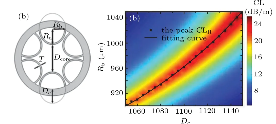
Fig. 5. (a) Cross-sectional diagram of S-ARF. (b) CLH as a function of Dc and Rb. Black squares represent peak points of CLH,and the black line represents the fitting curve.
To further study the key factors affecting the mode coupling in S-ARF,Rais varied from 900 µm to 1050 µm, andDcis varied from 1050µm to 1150µm. The CLHis depicted in Fig.5(b)as a function ofDcandRa, demonstrating that in a wide geometric deformation range of cladding tubes,the SARF could achieve a high CLH. The enlargement of cladding tubes in the ring direction of the fiber cross-section effectively enforces the suppression of the HOM.Shrinking the cladding from elliptical tubes to semi-elliptical tubes just slightly sacrifices the transmission performance of the FM. Moreover, the semi-elliptical cladding tubes provide a large contact area for the cladding mode with the extramural cladding,which significantly exacerbates the consumption on the HOM,and,finally,the CLHwas improved to more than 24 dB/m. When ARF has an optimal single-mode operation,the cross-sectional area ratio of cladding tubes and central air core is about 0.5:1.
2.3. Single-mode ARF with positive-curvature core
Our previous study[30]has confirmed that the singleoperation condition can be achieved in the ARFs with round cladding tubes, elliptical cladding tubes, and semi-elliptical cladding tubes based on the HOM suppression. Integrating with the investigations in this paper, it can speculate that the ARF can realize the single-mode operation by keeping the cross-sectional area ratio of core and cladding tube at 0.46:1.Meanwhile, that area ratio should be modified according to the number and the shape of cladding tubes. We proposed a simple-structured ARF with a positive-curvature core boundary to verify this speculation, as illustrated in Fig. 6(a). And this positive-curvature ARF comprises two inner and external cladding tubes, which are linked by several borders. When the cladding tube number,N, is varied from 6 to 8, andTis 106 µm, the values of CLFand CLHvarying withLare depicted in Figs. 6(c) and 6(d). WhenNis varied from 6 to 8,the area ratio of cladding tubes and core for optimal HOM suppression is 0.47:1, 0.44:1, and 0.415:1, respectively. Consistent with the previous speculation,this simple-structured ARF can realize a single-mode operation by adjusting the crosssectional area ratio of cladding tubes and core. But for the existence of the conjoint points, the mode in the central air core is consumed distinctly.
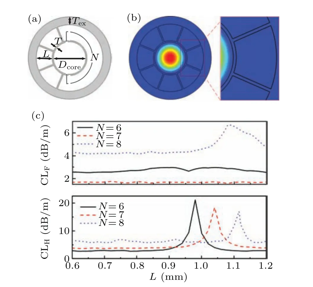
Fig.6. (a)Cross-sectional diagram of the ARF with positive-curvature core.(b)Electric field distribution of the FM in the ARF with N =8. In the fiber with different N,the values of CLF (b)and CLH (c)varying with L.
It is worth noting that, in Fig. 6(c), the CLFof the ARF withN=8 appears an abnormal increase whenLapproaches 1.1 mm. The electric field distribution of the FM in the ARF withN=8 is depicted in Fig. 6(b), and it demonstrated that the FM in core can slightly couple with the mode in the wall of core boundary,which increases the value of CLF. It can be seen, this coupling between core and the mode in the wall of core boundary is related to the cladding tube number and the size of cladding tube.
2.4. Single-mode ARF with negative-curvature core
In single-mode S-ARF, the gaps between cladding tubes are small, which difficult the manufacture. The conjoint points among cladding tubes are confirmed to affect the transmission loss of fiber,[14]and the conjoint cladding tubes have the potential for FM suppression and HOM suppression. In this paper, we optimized the nodeless cladding tubes of S-ARF into nodal cladding tubes and proposed a nodal S-ARF as illustrated in Fig. 7(a). In nodal S-ARF,the core diameter,Dcore, is maintaining at 2 mm, and the round tubes have a diameter ofdand a shell thickness ofT. The round tubes conjoin with each other and forming a common wall,besides,simultaneously,numbers of thin walls with a length ofLand a thickness ofTlink the common borders with the external cladding. In nodal S-ARF with 6 cladding tubes, the value of CLHas a function ofdandLis depicted in Fig. 7(b), demonstrating that the structural deformation of cladding tubes could significantly affect the loss of HOM.The nodal S-ARF can achieve the highest CLHabout 28 dB/m which is higher than that of S-ARF by deforming the cladding tubes. What is noteworthy is that, whendis 2.2 mm,there is an obvious fault in the distribution of peak value in Fig.7(b).In this fault,the value of CLHis smooth and more significant than 10 dB/m whenLis varied from 0.2 mm to 0.6 mm.When deforming the cladding tubes of ARF, the value of CLFis depicted in Fig.7(c),and there are two distinct high loss bands whenDis 2.18 mm and 2.3 mm,which have no effect on the single-mode characteristic of fiber.
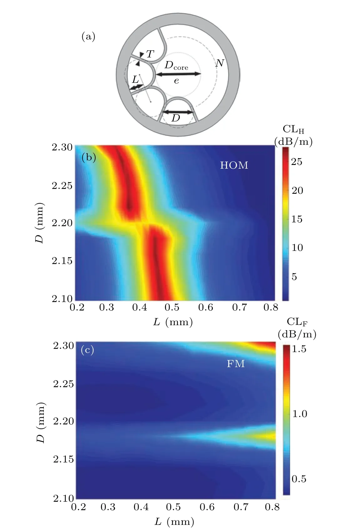
Fig.7.(a)Cross-sectional diagram of the ARF with a positive-curvature core.In the fiber with different numbers of cladding tubes, the values of CLF (b)and CLH (c)varying with L.

Fig. 8. (a) The electric feild distributions of HOM when L = 0.35 mm,D=2.22 mm, and (b) when L=0.45 mm, D=2.2 mm. (c) In the nodal S-ARF with 6 cladding tubes,CLH as a function of D and Dcore.
In the nodal S-ARF with 6 cladding tubes, whendi s 2.22 mm,andLis 0.35 mm,fbier has an optimal suppression on HOM,and fgiure 8(a)depicts the electric feild distribution of nodal S-ARF. It can be seen that the mode in core couples with the mode in cladding tubes,as well couples with the mode in core boundary(core boundary mode).In this nodal SARF,the coupling of core mode and the core boundary mode is always simultaneous with the coupling of core mode and cladding modes which endows fiber an additional suppression on HOM. Whendis 2.2 mm, andLis 0.45 mm, the electric field distribution of the nodal S-ARF is depicted in Fig.8(b).It demonstrates that the core mode forcefully couples with the core boundary mode,which impedes the coupling of core mode and the mode in cladding tubes. WhenLis 0.45 mm,the value of CLHas a function ofDcoreandDis depicted in Fig. 8(c), and there is an obvious value contrast of CLH. In Fig. 8(c), the value contrast of CLHdistributes linearly; and it demonstrates that the coupling between the core mode and core boundary mode is strongly affected by the diameter ratio ofDcoreandD.
When the cladding tube number of nodal S-ARF,N,is donated at 7 and 8,the values of CLHas functions ofDandLare depicted in Figs.9(a)and 9(b). Both the nodal S-ARFs with 7 and 8 cladding tubes can achieve an excellent suppression for HOM.Furthermore,the HOM suppression is mainly affected byL. Besides,in the nodal S-ARF with 7 cladding tubes,the peak value of CLHis higher than 30 dB/m and, simultaneously,the value of CLFis still less than 0.4 dB/m. When fiber is in optimal HOM suppression, HOMs of the nodal S-ARFs with different cladding tubes are depicted in Figs. 9(c) and 9(d),demonstrating the coupling between core mode and core boundary mode is still efficient in the nodal S-ARF with 7 or 8 cladding tubes.
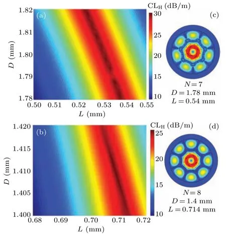
Fig.9. In the nodal S-ARFs with 7 cladding tubes(a)and 8 cladding tubes(b), CLH as functions of D and Dcore. (c) The electric field distributions of HOM when N is 7; D is 1.78 mm and L is 0.54 mm. (d) The electric field distributions of HOM when N is 8;D is 1.4 mm and L is 0.714 mm.
3. Conclusion
This paper numerically investigated the index-induced mode couplings between core and cladding in THz ARFs.Based on the coupling of the higher-order mode in core and the fundamental mode in cladding tubes, ARFs can achieve a remarkable single-mode operation. The single-mode operation was proved can be obtained in ARFs, so long as satisfy the condition that the ratio of the cross-sectional area inside the cladding tubes to that of the central air core is kept at 0.46:1,and this area ratio also should be modified according to the shape and the number of cladding tubes. For the ARFs with 6 cladding tubes,when the form of the cladding tube is out of round, the area ratio of cladding tubes and core for optimal single-mode operation is slightly larger than 0.46:1; meanwhile,this area ratio is somewhat decreased when the number of cladding tubes is larger than 6. Besides, in the ARF with conjoint cladding tubes,the nodal core boundary is found can enhance the suppression on higher-order mode; accordingly,this paper proposed a single-mode ARF with conjoint semielliptical cladding tubes. Compared with the ARFs with nodeless cladding tubes, this nodal ARF has an almost identical fundamental mode loss but a larger higher-order mode loss.
猜你喜欢
杂志排行

Chinese Physics B的其它文章
- Transient transition behaviors of fractional-order simplest chaotic circuit with bi-stable locally-active memristor and its ARM-based implementation
- Modeling and dynamics of double Hindmarsh–Rose neuron with memristor-based magnetic coupling and time delay∗
- Cascade discrete memristive maps for enhancing chaos∗
- A review on the design of ternary logic circuits∗
- Extended phase diagram of La1−xCaxMnO3 by interfacial engineering∗
- A double quantum dot defined by top gates in a single crystalline InSb nanosheet∗