Simulated annealing-based optimal design of energy efficientternary extractive dividing wall distillation process for separating benzene-isopropanol-water mixtures
2021-08-26MinLiYueCuiXiaojingShiZhishanZhangXiaoxiaoZhaoXiuyuZhuJunGao
Min Li,Yue Cui,Xiaojing Shi,Zhishan Zhang*,Xiaoxiao Zhao,Xiuyu Zhu,Jun Gao
College of Chemical and Biological Engineering,Shandong University of Science and Technology,Qingdao 266590,China
Keywords:Extractive distillation Dividing wall column Simulated annealing Optimization Benzene/isopropanol/water
ABSTRACT This article investigates the performances of different extractive distillation processes intensified with dividing-wall column for separating benzene-isopropanol-water ternary mixtures.All the processes with ethylene glycol as solvent are optimized with the minimal total annual cost (TAC) as target.In order to get the global optimal solution intelligently,an improved simulated annealing algorithm is adopted,which is programmed in MATLAB and linked to Aspen Plus.The results show that the extractive dividing wall column-solvent (EDWC-S) process consisting of an extractive dividing wall column and a solvent recovery column is the best scheme.It can reduce the TAC by 28.65%and CO2 emissions by 32.84%compared to the conventional triple-column extractive distillation process.
1.Introduction
Benzene and IPA are both good organic solvents and important fundamental chemicals.IPA is also used as alkylation reagent of benzene to produce isopropyl benzene or n-propyl benzene.A ternary mixture containing most of benzene and isopropanol(IPA) and a small amount of water is often generated in chemical and pharmaceutical industries.This mixture must be separated in order to improve the efficient use of resources and protect the environment.But it is hardly achieved by conventional distillation due to the presence of multiple binary or ternary azeotropes.Some special distillation methods have to be selected such as extractive distillation [1–4],pressure-swing distillation [5–10],azeotropic distillation [11–13],and reactive distillation [14–17].
Extractive distillation is widely used in separation of azeotropic or narrow boiling mixtures due to the flexibility and extensiveness of extractant selection,such as IPA-water[18,19],tetrahydrofuran/water [20,21],cyclohexane/cyclohexene [22,23],ethyl acetate/ethanol/water [24],and acetone/methanol/butanone/tert-butyl alcohol [25] systems.At the same time,the application of thermally coupling technologies in extractive distillation has been actively studied to reduce energy usage and economic costs.For example,Zhang et al.[26] completed the design and control of extractive dividing wall column(EDWC)and side stream extractive distillation process for separating propylene oxide–methanol–wat er mixture using water as entrainer.Kiss et al.[27]studied extractive distillation and azeotropic distillation for ethanol dehydration using ethylene glycol and n-pentane as solvents respectively,and strengthened the processes via dividing-wall columns.Zhao et al.[28]studied the process of separating ternary azeotropic mixtures of tetrahydrofuran/ethanol/water by EDWC using dimethyl sulfoxide and ethylene glycol as mixed entrainer.In the above studies,the sequential iterative method was used to determine the best process conditions.However,it is not always effective and also time-consuming as the increase in optimization size and complexity.In this case,two nontraditional optimization methods of simulated annealing (SA) and genetic algorithm (GA) are good choices,which can solve the optimal design of complex distillation configurations efficiently.For instance,Modla et al.[29] separated acetone/methanol azeotrope by extractive distillation and pressure swing distillation and adopted GA in optimizing both processes.Ma et al.[30] developed two extractive distillation processes with ionic liquid(1-ethyl-3-methylimidazole dicyandiamide)as solvent to separate IPA-water azeotrope,and applied multi-objective GA to determine optimal process parameters.Sun et al.[31] proposed three-column extractive distillation to separate acetonitrile/ethanol/water azeotrope using dimethyl sulfoxide as the most suitable solvent,and also used an improved multi-objective GA to optimize this process with a large number of continuous and discrete decision variables.Yang and Ward[32]applied the SA algorithm to the optimization of binary systems (acetone/methanol,n-hexane/ethyl acetate and n-hexane/tetrahydrofuran) with double-column extractive distillation using multiple solvents.Yang et al.[33]achieved design and optimization of double-thermally coupled extractive distillation in the separation of benzene/toluene/cyclohexane system by applying an improved GA.

Fig.1.The CED (benchmark) process with detailed optimization information (1 atm=101325 Pa).
In our past works,we compared two schemes of pressure-swing distillation and heterogeneous azeotropic distillation used to separate benzene/IPA/water mixture based on optimum design and operating conditions and simultaneously considered partial heat integration [34].Also,we put forward side stream extractive distillation processes with high energy efficiency for separating the same system and implemented process optimization by an improved SA algorithm [35].Beyond that,few studies on benzene/IPA/water separation have been reported so far.The current article aims to investigate the energy efficiency and economics of another extractive distillation thermal coupling process with dividing wall column for the separation of benzene/IPA/water mixtures.Three different EDWC-based configurations are proposed and optimized with minimum total annual cost (TAC) by using the SA-based optimization method.Multiple indicators including economic cost,energy consumption and CO2emission are analyzed to determine the best scheme.

Fig.2.Three kinds of intensified flowsheets from benchmark process.(a) E-EDWC,(b) D-EDWCs,and (c) EDWC-S.
2.Methodology
2.1.Interpretation of benchmark process
The conventional extractive distillation (CED) process that has been optimized in our previous work [35] is regarded as benchmark process of this current study,as depicted in Fig.1.This process includes two extractive distillation columns (EDC1,EDC2) and one solvent recovery column (SRC).Ethylene glycol(EG) is selected as a solvent.The fresh feed has the flowrate of 100 kmol∙h-1and the composition of 30% (mol) of benzene,60% (mol) IPA and 10% (mol) water.The product purities are required as 99.5% (mol) benzene,99.5% (mol) IPA and 99.9%(mol) water respectively.During that optimization,the nonradom two liquid (NRTL) model was used because of the good consistency between experimental and calculated data.The SA algorithm with the TAC as an objective function was adopted.The detailed calculations of TAC and CO2are shown in S1–S2 of the Supplementary Material.
2.2.Intensification of benchmark process
The benchmark process can be intensified by integrating two of the three columns into one column shell,as given different combination schemes in Fig.2.In Fig.2a,the two columns of EDC2 and SRC are integrated into one column (i.e.,EDWC).The bottom stream from EDC and the solvent FS2are fed to the EDWC.IPA is obtained at the top of EDWC.Water and solvent are separated in the right part of EDWC.One part of the base solvent is fed back into the left part of EDWC,and the other part returns to the EDC.The benzene product is still extracted at the top of EDC.This flow sheet made up of EDC and EDWC is known as E-EDWC.
In Fig.2b,the solvents FS1and FS2required by EDC1 and EDC2 are recovered in two units respectively.The EDC1 and itself solvent recycling is achieved in one column (i.e.,EDWC1).The fresh feed and the solvent FS1are fed to the EDWC1.Benzene as overhead product is obtained in the left part of EDWC1.The high-purity solvent at the bottom of EDWC1 returns to the left part.The top stream in the right part of EDWC1 is a binary mixture of IPA and water.Similarly,the EDC2 and itself solvent recycling is also carried out in one column (i.e.,EDWC2).IPA is obtained at the top of EDWC2.Water and solvent are separated in the right part of EDWC2.The high-purity solvent at the bottom of EDWC2 goes back into the left part.This flow sheet consisted of EDWC1 and EDWC2 is named as D-EDWCs.

Fig.3.The equivalent thermally-coupled configurations with initial design parameters:(a) E-EDWC,(b) D-EDWCs,and (c) EDWC-S.

Fig.4.The SA optimization program coupling with process simulator.
In Fig.2c,the two columns of EDC1 and EDC2 are combined into one column(i.e.,EDWC).The fresh feed and the solvent FS1are fed to the left part of EDWC while the other solvent FS2is introduced from the right part.Benzene and IPA as overhead products are obtained at left and right parts of the EDWC,respectively.The bottom stream is a binary mixture of water and solvent,and is further separated into water product and high purity solvent in the SRC.This flow sheet composed of EDWC and SRC is called as EDWC-S.
2.3.Process optimization
The process optimizations are conducted with TAC as a goal by the combination approach between SA algorithm and Aspen Plus simulator.After the optimization result is determined,CO2emission is calculated to evaluate these processes from the perspective of environmental impact.
2.3.1.Variables
In this study,all columns are operated under atmospheric pressure.The temperature and composition of the recycling solvent are set as 320 K and 99.999% (mol).All parameters to change during process optimization are in detail listed in Table 1,as well as the degrees of freedom of each column.The design (dependent) variables are continuously adjusted to meet the product purity or recovery constraints by using the function of‘‘Design specification”in Aspen Plus simulator,including reflux ratios(RR),distillate flowrates(D)and side-vapor flowrates(FV).The optimization(independent)variables in the SA procedure for minimizing the TAC are the solvent flowrates (FS) and some discrete parameters such as the number of theoretical stages (NT),feed stages (NF),solvent stages(NS) and side-vapor stages (NV).Fig.3 gives the equivalent thermally-coupled configurations used for the subsequent simulation and initial design parameters.

Table 1Design and optimization variables of the proposed processes
2.3.2.SA algorithm
The SA algorithm is derived from the principle of solid metal annealing.Fig.4 gives the suitable optimization program specifically for the above EDWC processes.The algorithm’s important parameters including initial temperature (T0),terminal temperature(Tf),annealing factor(α),Markov chain length(Markov),Boltzmann constant (k) are explained in S3 of the Supplementary Material.The separate code is designed by MATLAB and integrated with Aspen to carry out the process optimization.The code for the SA algorithm implementation is given in detail in S4 of the supplementary Material.Of note is that upper and lower bounds of the optimization variables are first determined by using the‘‘Sensitivity analysis” function of Aspen Plus before implementing the SA algorithm.
3.Results and Discussion
3.1.Optimization results
The optimization of each process is implemented for three turns at least to get the real global optimal solution.Tables 2–4 show the detailed changes during several turns of optimization for the three processes of E-EDWC,D-EDWC and EDWC-S respectively.Obviously,the economic and energy performances of each process are gradually improved to the optimal conditions.The stable solution is obtained in no more than 6 hours each turn,so the SA algorithm is very time-efficient for the optimal design of different EDWC processes.The whole optimization program runs on Windows 10 with Intel®CoreTMi7-7700HQ CPU @ 2.80 GHz,16 GB memory.Thedetailed optimal information is found in Figs.S1–S3 of the Supplementary Material.
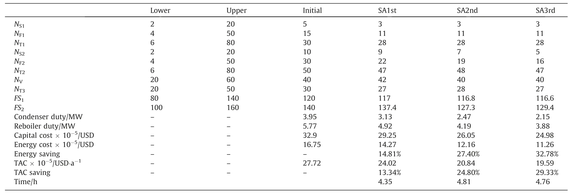
Table 2The detailed changes during several turns of optimization for the E-EDWC process

Table 3The detailed changes during several turns of optimization for the D-EDWC process

Table 4The detailed changes during several turns of optimization for the EDWC-S process

Fig.5.Comparison in aspects of TAC and CO2 emission.
3.2.Comparison
A comparison between TAC and CO2emissions between the four scenarios is given in Fig.5.In comparison with the CED configuration,three EDWC schemes (E-EDWC,D-EDWC and EDWC-S)save TAC by 23.95%,9.86%,28.65%,and reduce CO2emission by 22.96%,16.30%,32.84%,respectively.The EDWC-S configuration,which is a direct sequence,is better than the indirect sequence D-EDWC configuration,reducing 20.84%TAC and 19.76%CO2emissions.The configuration of transforming the last two columns of the CED into a dividing wall column (D-EDWC) is slightly worse than the configuration of transforming the first two columns(EDWC-S),but the difference is not significant.The EDWC-S configuration saves 6.18% TAC and 12.82% CO2emissions,respectively,compared to the D-EDWC configuration.In a word,the proposed EDWC-S configuration is not only more energy efficient but also superior to other processes in terms of economic costs and environmental protection.
3.3.Analysis of the EDWC-S scheme
Fig.6 shows a flow chart of the EDWC-S configuration with detailed information.Further,a makeup of EG (0.038 kmol∙h-1)needs to be added to the solvent to compensate for the loss of entrainer in the product stream.The optimal flowsheets of EEDWC and D-EDWC with detailed information are provided in Figs.S4–S5 of the Supplementary Material.
Fig.7 shows the liquid composition and exergy loss profiles of the three columns.All azeotropes in the MC and the SC are broken due to the addition of EG.Hence,benzene as the lightest component rises sharply in the MC,and reaches the high purity of 99.5% (mol) in the first tray (condenser).The high-purity IPA as the second lightest component is obtained in the SC.On the 25th tray,the compositions of IPA and EG have a sudden change because the vapor side-stream is removed and the liquid side-stream is introduced.The exergy loss occurs mostly at the feed location due to the difference in feed temperature.Except for this,DWC can effectively reduce the exergy loss and back-mixing.The detailed calculation of exergy is shown in S5 of the Supplementary Material.
4.Conclusions

Fig.6.The optimal EDWC-S flowsheet with detailed information.

Fig.7.Liquid composition and exergy loss in (a,b) column MC,(c,d) column SC and (e,f) column SRC.
This article investigated three enhanced processes for benzene/IPA/water separation with EG as solvent,i.e.,E-EDWC,D-EDWC and EDWC-S,and accomplished economic optimization by using the SA algorithm.The results showed that the EDWC-S process was the most efficient scheme and achieves substantial reductions in the TAC and CO2emission,up to 28.65%and 32.84% in comparison with the CED process.The computation proved that this combined optimization between SA algorithm and Aspen simulator can get the global optimum solution quickly and efficiently,which is especially applicable for the optimization of multi-column distillation process and complex thermally-coupled configuration.
The proposed EDWC configurations and optimization algorithm is also adapted to the separation of other ternary mixtures with more than one azeotropes such as methanol/acetonitrile/benzene,tetrahydrofuran/methanol/water,and methanol/butanone/tertbutanol mixtures.But its application in multi-objective optimization or pressure-swing distillation process needs further tion or pressure-swing distillation process needs further discussion.
Declaration of Competing Interest
The authors declare that they have no known competing financial interests or personal relationships that could have appeared to influence the work reported in this paper.
FAVc knowlefdlogwe mraeten tosf
This wfoerekd w staasg seuspported by the National Natural Science Foun-NdaStion of sCohlvineant(2s1ta8g7e8s178).
Supplementary Material
Supplementary data to this article can be found online at https://doi.org/10.1016/j.cjche.2020.08.041.
Nomenclature
B bottom flow
D distillate flow
FS solvent flowrates,kmol∙h-1
FV flow rate of vapor side-stream,kmol∙h-1
MC main column
NFfeed stages
NSsolvent stages
NTtheoretical stages
NVside-vapor stages
RR reflux ratio
SC sub column
T0initial temperature,K
Tftermination temperature,K
杂志排行

Chinese Journal of Chemical Engineering的其它文章
- Comparison of catalyst-coated membranes and catalyst-coated substrate for PEMFC membrane electrode assembly:A review
- Experimental investigation of different brines imbibition influences on co-and counter-current oil flows in carbonate reservoirs
- Experimental investigation on the effect of surface characterization of electrodes on the gas bubble dynamics in electrolyte flow and performance of FLA batteries by using PIV
- Mechanically activated starch magnetic microspheres for Cd(II)adsorption from aqueous solution
- Robust,fluorine-free and superhydrophobic composite melamine sponge modified with dual silanized SiO2 microspheres for oil–water separation
- Efficient adsorption to hexavalent chromium by iron oxalate modified D301:Characterization,performance and mechanisms