双功能型嵌入镍纳米颗粒的碳棱柱状微米棒电极用于电化学甲醇氧化助力的节能产氢
2021-07-10吕琳张立阳何雪冰原弘欧阳述昕张铁锐
吕琳,张立阳,何雪冰,原弘,欧阳述昕,张铁锐
华中师范大学,化学学院,农药与化学生物学教育部重点实验室,武汉 430079
1 Introduction
The demand for renewable and environmentally friendly energy forms has been sharply soaring since the first industrial revolution with continuous depletion of fossil fuels which inevitably triggers environmental pollution and climate problems1,2. Nowadays, hydrogen is well acknowledged to be a sensible alternative for traditional fossil fuels due to its easy transportation and pollution-free combustion3,4. Traditionally,electrochemical water splitting composed of cathodic hydrogen evolution reaction (HER) and anodic oxygen evolution reaction(OER) is considered as one of the most highly efficient and convenient approaches to generate hydrogen gas5; however,high overpotential of OER resulted from the complicated four electron-transfer process seriously restricts the reaction efficiency of overall water splitting, making hydrogen production need to conquer a large cell voltage6. Hence, it remains a huge challenge to engineer highly efficient electrolyzer to drive high current densities at a low cell voltage.Considering the sluggish OER process which is the principal obstacle for high-efficient electrocatalytic cell, it can be replaced with another anodic reaction with low decomposition potential.Previously, more readily oxidized species such as ethanol, urea,hydrazine, 5-hydroxymethylfurfural and ammonia borane have been introduced to substitute OER to realize more energyefficient hydrogen production7–11. Methanol oxidation reaction(MOR), the general reaction equation: CH3OH (l) + 6OH−→CO2(g) + 5H2O (l) + 6e−12, which plays a significant role in promising direct methanol fuel cells (DMFCs), has been integrated with hydrogen evolution as well using Pt-based catalysts13,14; whereas, the bifunctionality is achieved mainly based on the noble-metal nanomaterials15,16, and Pt-based catalyst may well be poisoned by CO intermediates17, which impedes its wide application. As a result, seeking for earthabundant bifunctional catalysts is greatly crucial for industrial production. Ni-based electrocatalysts have appeared as promising candidates toward methanol oxidation and been widely investigated due to their low-cost, earth-abundance and relatively environmentally-friendly, and a great number of groups have devoted to the structural design of Ni-based electrocatalysts to achieve high-efficient methanol oxidation18,19.However, it remains a huge challenge to realize a versatile electrode utilizing Ni-based electrocatalysts to catalyze MOR and HER simultaneously.
In this work, we demonstrate that metal-organic framework(MOF)-derived non-noble metal-based electrocatalyst of Ni nanoparticle-embedded carbon (Ni@C) microrods could serve as a bifunctional electrode with high catalytic activity and durability for MOR in alkaline aqueous solution to realize energy-efficient hydrogen production. The Ni@C microrods delivered not only high activity toward MOR with a high current density of 51.6 mA·cm−2at a potential of 1.5 V (vsRHE(reversible hydrogen electrode)) but also remarkable durability with a subtle current decay of 2.8% under a 12-h continuous operation. Meanwhile, the Ni@C microrods exhibited an excellent HER activity with an overpotential of 155 mV at the current density of 10 mA·cm−2and a fairish stability over 12-h electrolysis. In this case, the Ni@C microrods can be considered as an available candidate as a bifunctional catalyst toward MOR and HER, and the cell voltage of the constructed hybrid electrolyser could be decreased by 240 mV at the current density of 10 mA·cm−2when replacing OER with MOR.
2 Experimental and computational section
All chemical reagents were directly used without any further purification. 2,5-dihydroxyterephthalic acid (DHTA, ≥ 98%)was purchased from Aladdin, nickel acetate hexahydrate (AR, ≥99%) and tetrahydrofuran (AR, ≥ 99%) were purchased from Sinopharm (China), and the commercial 20% (w, mass fraction)Pt/C was purchased from Hesen, Shanghai.
2.1 Synthesis of Ni-MOF-74 and Ni@C prism-like microrods
The precursor Ni-MOF-74 was preparedviaa facile hydrothermal method according to a previously reported literature with some modifications20. In a typical procedure, 1.5 mmol of DHTA and nickel acetate hexahydrate were dissolved in 15 mL of tetrahydrofuran and 15 mL of deionized water, then the two different solutions were well mixed up and kept stirring for 15 min. The mixture was transferred to a 50 mL Teflon-lined stainless steel autoclave and sealed immediately; the autoclave was then maintained in an oven at 110 °C for 24 h. After naturally cooling down to room temperature, the collected precipitate was washed with deionized water and absolute ethanol alternately for several times, and then was dried at 60 °C for 12 h.
The Ni@C microrods were obtainedviaan annealing process for carbonization of the precursor Ni-MOF-74. Typically, the precursor was heated up to 800 °C with a ramp rate of 5 °C·min−1and kept for 2 h; in the whole process, a flow rate of 60 mL·min−1of Ar was used to blow the gaseous byproduct away. The obtained product was washed accordingly.
2.2 Synthesis of carbon prism-like microrods
The carbon prism-like microrods (denoted as C) were obtainedviathe acid-etching treatment of the Ni@C microrods.Typically, the Ni@C microrods were etched in 1.0 mol·L−1HCl solution at 80 °C for 24 h. After that, the black product was washed with deionized water and absolute ethanol alternately for several times and then was subjected to an oven at 60 °C for 12 h.
2.3 Materials characterization
The crystal structures of the samples were characterized by Xray diffraction (XRD, X’pert Pro, Philips Netherlands; CuKα,λ= 0.15406 nm). The morphology images of the samples were captured with filed-emission scanning electron microscopy(FESEM, JSM-7100F, JEOL Japan) and transmission electron microscopy (TEM, Tecnai G2 F30, FEI Netherlands) equipped with energy dispersive X-ray spectroscopy (EDS). X-ray photoelectron spectroscopy (XPS, AXIS Ultra DLD-600W,Kratos, the United Kingdom, AlKα(1486.6 eV)) was employed to examine chemical states of surface of the samples.
2.4 Electrochemical characterization
All electrochemical measurements were implemented in a three-electrode configuration linked with a CHI 760E electrochemical workstation (Chenhua, Shanghai) except the cell test conducted in a two-electrode system. In the threeelectrode configuration, a Pt plate and Ag/AgCl (saturated with 3 mol·L−1KCl solution) served as the counter and reference electrodes, respectively; while a 1 × 1 cm2carbon paper coated with catalysts (with a mass loading ofca.0.5 mg·cm−2) was employed as the working electrode and 1.0 mol·L−1KOH aqueous solution added with various concentrations (0, 0.25, 0.5,0.75 and 1.0 mol·L−1) of methanol as the electrolytes. The cathodic and anodic compartments were separated from each other using a Nafion 117 membrane. All linear sweep voltammetry (LSV) curves were collected with 95% iRcompensation. Concerning the preparation of working electrodes, 5.0 mg of catalyst was dispersed in the mixture of 980 μL absolute ethanol and 20 μL Nafion solution (5.0% (w))and then was subjected to ultrasonic treatment for 40 min to generate homogeneous suspension. The 100 μL of suspension was dipped onto the tailored carbon paper (1.0 cm × 1.0 cm) with a pipette and was dried under an infrared lamp for usage. Prior to test, a continuous flow (20 mL·min−1) of Ar gas was poured into the electrolytes to eliminate possible effects that air might bring and maintained over the entire test. Gas chromatograph(GC, GC2030plus, Tet) and nuclear magnetic resonance (NMR,600M) were employed to detect the gas product and liquid product toward MOR. The calculation methods of faradaic efficiency toward MOR products are described in Supporting Information.
3 Results and discussion
The synthesis process of Ni@C microrods is illustrated in Fig.1. Ni-MOF-74 prism-like microrods were firstly preparedviaa facile hydrothermal method as the precursor and then a subsequent calcination in Ar atmosphere was carried out for carbonization to harvest the Ni@C microrods. In the annealing,the ligand DHTA was carbonized to be graphitic carbon, while Ni2+ions were directly reduced to be metallic nickel nanoparticles surrounded by the outer carbon layer, thus the interface between metal nanoparticles and carbon layer was well established, benefitting to the charge transfer from metal particles to carbon layer which might have positive effects on the balance of adsorption strength of different intermediates in electrochemical oxidation reactions21,22.

Fig. 1 Schematic illustration of the synthesis process of the Ni@C microrods.Blue, grey and red delegates nickel atom, carbon atom and oxygen atom, respectively. Color online.
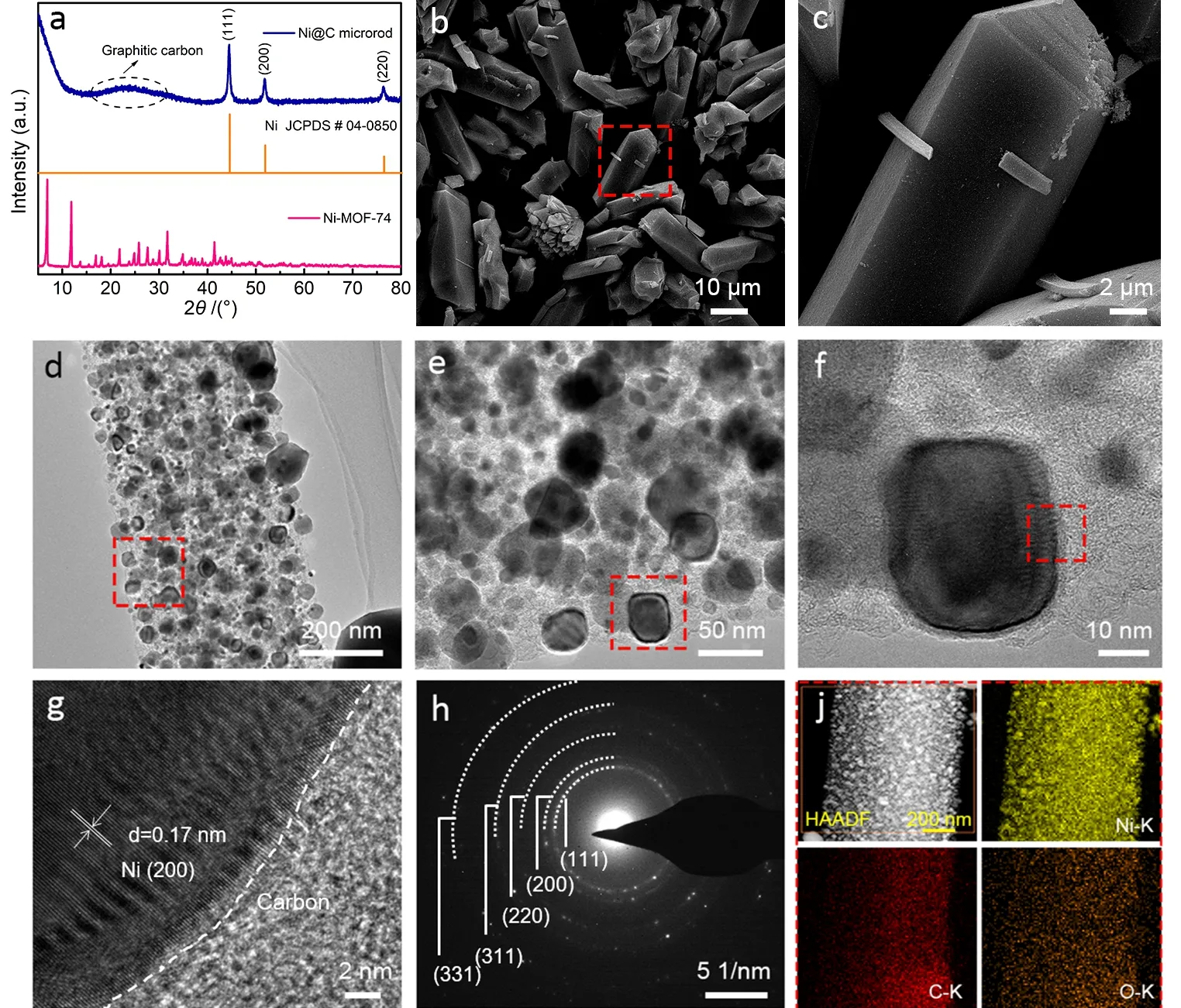
Fig. 2 (a) XRD patterns of the as-prepared Ni@C microrods and the precursor Ni-MOF-74; (b, c) FESEM images and(d–g) TEM images of Ni@C microrods with different magnifications; (h) SAED pattern of the Ni@C microrods;(j) HAADF-TEM image and the corresponding EDS elemental mapping of the Ni@C microrods.
To verify the crystal structures of the Ni@C microrods and the corresponding precursor Ni-MOF-74, powder XRD patterns were acquired. As shown in Fig. 2a, five strong peaks located at 6.8°, 11.8°, 25.7°, 31.7° and 41.4° for the Ni-MOF-74 are observed, which is in well agreement with the previous report and the simulated XRD pattern (Fig. S1a)20, indicating that Ni-MOF-74 was successfully prepared. After the carbonization treatment, the Ni@C microrods were obtained. In the corresponding XRD pattern, three typical peaks at 44.5°, 51.8°and 76.3° corresponding to metal Ni of cubic phase (indexed as JCPDS # 04-0850) are apparently detected. In addition, a broad peak at around 23.9° is also caught, which is attributed to the graphitic carbon23. As a result, it is proved that the Ni@C microrods are composed of metal Ni and graphitic carbon. For contrast, the XRD pattern (Fig. S1b) of the individual C derived from acid-etching treated Ni@C microrods was also collected,in which two typical peaks located at 20.7° and 43.8° are ascribed to the graphitic carbon24. After the analysis of the crystal structures, the microstructures of the samples were unveiled by FESEM and TEM. It is revealed that the microstructures of Ni-MOF-74 exhibit uniform prism-like microrods with the length of 18–22 μm and width of 6–8 μm(Fig. S2) and its surface seems smooth and no conspicuous porosity is inspected. As for the carbonized product of Ni@C, it inherits the prism-like structure of the former and the size is almost not changed (Fig. 2b). It is worth-noted that the surface of the Ni@C is rough and holey after the carbonization (Fig. 2c),indicating a porous structure is generated due to the dehydrogenation and deoxygenation of the ligand DHTA. To acquire exquisite structural characteristics of the Ni@C, TEM and high resolution TEM (HRTEM) images were captured.Obviously, numerous Ni nanoparticles with sizes of 30–50 nm are embedded in carbon microrod (Fig. 2d). In a magnified image (Fig. 2e), it is observed that masses of ultrafine Ni nanoparticles with sizes of around 10 nm are distributed everywhere. In a typical image of high magnification (Fig. 2f),the selected nanoparticle seems to be a cube-like structure with irregular borders, which may be induced by the intrinsic crystal structure of cubic phase of metal Ni. The elaborate interface between Ni nanoparticle and carbon could be vividly observed in a HRTEM image (Fig. 2g), and the interplanar spacing is calculated to be 0.17 nm from the regular lattice fringe of the selected nanoparticle, which corresponds to the facet (200) of metal Ni with cubic phase, confirming the interfacial structure of the Ni@C microrods. To further affirm the structural composition of the sample, a selected area electron diffraction(SAED) image was collected. As shown in Fig. 2h, multiple concentric annuluses are captured, demonstrating polycrystalline structure of Ni nanoparticles. Moreover, the interplanar spacings are calculated to bed= 0.20 nm, 0.17 nm,0.12 nm, 0.10 nm and 0.08 nm from these circles, which matches well with facet (111), (200), (220), (311) and (331) of metal Ni of cubic phase, which is in well agreement with the corresponding XRD pattern. The elemental composition and distribution of the Ni@C microrods was examined by TEM energy-dispersive X-ray spectroscopy (TEM-EDS). High-angle annular dark filed (HAADF) image and the corresponding element mapping are presented in Fig. 2j, and it can be validated that the nanoparticles belong to metal Ni indeed and the surrounding light color area should be assigned to the carbon skeleton; while the oxygen species stems from the oxidized surface due to the exposure to air. From the corresponding elemental composition (Fig. S3), it can be concluded the composite mainly consists of Ni and carbon elements, and the molar ratio of Ni/C in the composite is 1.54 : 1.00 and no drastic oxidation is found; in addition, the peaks for Cu are attributed to the carbon film.
To probe the chemical valences of the Ni@C microrods, Xray photoelectron spectroscopy (XPS) was carried out. As shown in Fig. S4, the survey spectrum demonstrates the existence of Ni,O and C elements. In the core level spectrum of Ni 2p(in Fig.3a), a pair of peaks at 870.1 eV and 852.9 eV was ascribed to Ni02p1/2 and Ni02p3/2, while another two pairs of peaks at 871.2 eV and 873.8 eV, and 854.0 eV and 856.2 eV were attributed to Ni2+2p1/2, Ni2+2p3/2, respectively, accompanied with three peaks at 859.3 eV, 861.5 eV and 879.6 eV were satellite peaks forNi02p3/2 sat., Ni2+2p3/2 sat. and Ni2+2p1/2 sat.25,26,ascertaining the composition of zero-valent metal Ni and surfacial divalent Ni. The core level spectrum of C 1s(Fig. 3b)is deconvoluted into four peaks at 284.7 eV, 285.3 eV, 286.6 eV and 289.3 eV, ascribing to C―C, C=O, C―O and O―C=O27,28,respectively, and it comes out that the bonding between carbon and oxygen is mainly attributed to the oxygen species in DHTA and the inevitable oxidation by air. Since the existence of subtle surface oxidation in air, the core level spectrum of O 1swas analyzed as well. It can be conspicuously observed that four peaks at 529.9 eV, 531.5 eV, 532.6 eV and 533.9 eV are deconvoluted, associating with the lattice oxygen O2−, O=C,Ni―OH and O―C due to the formation of amorphous nickel oxide/hydroxide by exposure in air28–30. The elemental composition of surface/subsurface of Ni@C microrods (Table S1) is determined by XPS analysis as well, and the higher content of C compared with the EDS result further certifies the tight encapsulation to nickel nanoparticles by graphitic carbon.

Fig. 3 High-resolution XPS spectra of the Ni@C microrods for(a) Ni 2p, (b) C 1s and (c) O 1s.
To investigate the electrocatalytic methanol oxidation and hydrogen evolution activity of the as-prepared samples,electrochemical measurements in a three-electrode configuration were conducted. Firstly, cyclic voltammetry (CV)tests of the Ni-MOF-74 and Ni@C in different electrolytes were investigated. The CV curves at the scan rate of 50 mV·s−1of the Ni@C in 1.0 mol·L−1KOH aqueous solution containing different concentration of methanol are shown in Fig. 4a. It is clearly observed that the current density sharply arises with the concentration of methanol increasing from 0 mol·L−1to 0.5 mol·L−1, indicating the efficient MOR; while no obvious change of current density is found when the concentration of methanol continuously increases to 1.0 mol·L−1, manifesting the nonpositive correlation between the MOR activity and concentration of methanol due to the limited migration rate of methanol molecules. As shown in Fig. 4b, after carbonization, the Ni@C microrods exhibit a significant increase in current density compared with that of Ni-MOF-74 catalyst and individual C,prominently superior to the commercial Pt/C as well (Fig. S5).For comparison, the CV curves of the individual C in the solution with the presence and absence of methanol are provided. It is apparent that the individual C exhibits almost no activity toward MOR and OER (Fig. S6). Particularly, it is explicitly seen from the inset of Fig. 4b that the current density (51.6 mA·cm−2) of the Ni@C is twice higher than that of the precursor Ni-MOF-74(24.3 mA·cm−2). Methanol electro-oxidation occurs in two process according to previous report12, and the redox process on the electrode surface can be summarized using the following equations:
NiO + OH−→ NiOOH + e−
NiOOH + CH3OH + O2→ Ni(OH)2+ product + H2O
Firstly, Ni2+ions are oxidized to Ni3+or higher valence states.Secondly, Ni3+ions are reduced back to Ni2+ions by methanol molecules at the same time. Actually, the formed NiOOH species are the real active centers for MOR, and the current density in the reduction part is decreased compared with that in OER process, which can be associated with the reduction of a fraction of NiOOH by methanol.

Fig. 4 (a) CV curves of the Ni@C microrods toward different concentrations of methanol; (b) CV curves of the Ni-MOF-74, Ni@C and individual C toward 0.5 mol·L−1 methanol solution (inset is the contrast of current densities at 1.5 V); (c) Tafel plots for the Ni-MOF-74,Ni@C and individual C; (d) LSV curves of the Ni@C at different scan rates; (e) The capacitive current densities at 1.15 V (vs RHE) as a function of scan rate for the samples; (f) Nyquist plots for the Ni-MOF-74, Ni@C and individual C; (g) Long-term stability test of the Ni@C at 1.5 V (vs RHE);(h) CV curves of the Ni@C before and after stability test. All the experiments of MOR are carried out in 1.0 mol·L−1 KOH aqueous solution.
The kinetics of MOR was estimated by Tafel plots. As shown in Fig. 4c, the lower Tafel slope (51 mV·dec−1) of Ni@C than that of Ni-MOF-74 (72 mV·dec−1) implies a faster electrochemical kinetic process. Regarding the mechanism of MOR, mass transport plays a crucial role in determining the MOR activity31. Hence, LSV curves at various scan rates were collected to evaluate the mass transport of the Ni@C toward MOR. It is clearly shown in Fig. 4d that negligible change in activity is observed along with the increase of scan rate from 5 to 100 mV·s−1, suggesting the adequately rapid mass transport of the Ni@C toward MOR. To further study the intrinsic MOR activity of the as-prepared catalysts, electrochemical active surface areas (ECSAs) were examined by evaluating the doublelayer capacitance with the potential range from −1.10 to −1.20 V(Fig. S7). As clearly seen in Fig. 4e, theCdlvalue of Ni@C is more than twice that of Ni-MOF-74, implying the Ni@C possesses a much higher ECSAs than the Ni-MOF-74. To gain more insights into the MOR kinetics, electrochemical impedance spectroscopy (EIS) was conducted at the potential of 1.4 V. As shown in Fig. 4f, the similar starting point in the spectroscopy indicates that the same resistance of solution (Rs) while the much smaller semicircle diameter of the Ni@C suggests a lower contact resistance and charge transfer impedance (Rct) compared with that of the Ni-MOF-74 and individual C32,33. From a perspective of industrial application, high durability is extremely significant for catalysts to be directly adopted in industrial production. Therefore, a 12-h long-term stability test for the Ni@C at the potential of 1.5 V was carried out. From Fig. 4g,only 2.8% decay (from 50.9 to 49.5 mA) is found after 12-h test compared with the steady state in the first hour, and the high stability is further confirmed by the CV curves (Fig. 4h) of the catalyst before and after 12-h stability test. Additionally, an apparent anodic peak assigned to the transformation from divalent Ni to trivalent Ni is observed after the stability test (in the inset of Fig. 4h)32, suggesting the surface oxidation of the catalyst during the MOR process. Gas chromatograph (GC) and nuclear magnetic resonance (NMR) were employed to detect the gas product and liquid product toward MOR, respectively. A potential of 1.55 V was applied to conduct the faradaic efficiency test toward MOR (Fig. S8). The results indicate the products are composed of CO2and formate (Figs. S9 and S10), the faradaic efficiencies toward CO2and formate were calculated to be 36.2% and 62.5%, which reveals that MOR is more thermodynamically favorable than OER. To confirm the real active centers for MOR, the Ni 2pcore level of XPS spectrum for the Ni@C after 12-h stability test was collected (Fig. S11). It is clear that a pair of peaks at 855.9 eV and 873.6 eV for Ni3+2p3/2 and Ni3+2p1/2 are deconvoluted with two satellite peaks at 861.8 eV and 880.3 eV, respectively25,34. Therefore, NiOOH species are real active centers for MOR, and pristine Ni2+ions on the surface have been oxidized to Ni3+during MOR process.To the best of our knowledge, the Ni@C microrods yield a comparable MOR performance to the most of recently reported Ni-based catalysts (Table S2). In a word, from all the MOR electrochemical tests, it can be concluded that the Ni@C microrods possess not only high MOR activity but remarkable stability due to the dual interfacial charge transfer,i.e., Ni/C and Ni/NiOx, imparting the catalyst application potential in industrial production.

Fig. 5 (a) LSV curves of the Ni-MOF-74, Ni@C, individual C and commercial 20% Pt/C; (b) Nyquist plots for the Ni-MOF-74, Ni@C and individual C; (c) Long-term stability test of the Ni@C at the current density of 10 mA·cm−2. All the experiments of HER are conducted in 1.0 mol·L−1 KOH containing 0.5 mol·L−1 methanol and all LSV curves were corrected with 95% iR-compensation.

Fig. 6 (a) LSV curves of methanol electrolysis and water electrolysis for the Ni@C in a two-electrode configuration with a scan rate of 5 mV·s−1; (b)Cell voltage of methanol electrolysis and water electrolysis at the current density of 10 mA·cm−2; (c) Chronopotentiometric curve for Ni@C ǁ Ni@C couple at the current density of 10 mA·cm−2; (d) Schematic diagram of the full-cell in which the Ni@C microrods serve as both the anode and cathode.
To validate the bifunctionality of the Ni@C microrods, HER performance was also examined in a three-electrode system with 1.0 mol·L−1KOH aqueous solution containing 0.5 mol·L−1methanol as electrolyte. As shown in Fig. 5a, the Ni@C delivers a low overpotential of 155 mV at the current density of 10 mA·cm−2, while no obvious cathodic current within the fixed potential window is observed on Ni-MOF and the individual C,indicating the Ni@C is much more active toward HER than the inert Ni-MOF-74 and the individual C, behind the commercial Pt/C yielding a low overpotential of 61 mV. To gain more insights into the catalytic kinetics of HER, EIS was also collected at an open potential of −200 mV. Fig. 5b suggests that the Ni@C has a much smaller semicircle diameter than the Ni-MOF-74 and C, indicating it possesses a lowRct. Durability of catalysts is of great significance for industrial production so that the long-term stability curve of the Ni@C by chronopotentiometric test at the current density of 10 mA·cm−2is obtained. The potential for the Ni@C increases by 101 mV after a 12-h electrolysis (Fig. 5c), which could be aroused by the continuous reduction of oxidized Ni centers on the surface25.
To verify the bifunctionality of the Ni@C for MOR and HER,a two-electrode electrolyzer with the Ni@C as both cathode and anode electrode was made to evaluate the cell performance. The Ni@C ǁ Ni@C couple delivers a large current density for methanol electrolysis at the same potential as shown in Fig. 6a,which identifies the high efficiency of methanol oxidation assisted hydrogen production. The cell voltage can be decreased by 240 mV (Fig. 6b) when MOR serves as the electrochemical anodic reaction compared with OER. Fig. 6c shows the cell stability for Ni@C ǁ Ni@C couple and it is clearly observed that the cell voltage increases up to 1.84 V after a 20-h continuous operation, which could be attributed to the unstable HER due to the reduction of oxidized Ni species. These results demonstrate the bifunctionality of the Ni@C and indicate that substituting oxygen evolution with methanol oxidation in the anode can more efficiently catalyze hydrogen production. As shown in Fig. 6d,the Ni@C microrods serve as both the anode and cathode in the full-cell to drive the electrolysis reactor comprised of MOR and HER, and the corresponding optical image of the electrochemical hybrid test system is provided in Fig. S12.
4 Conclusions
In summary, the MOF-derived Ni@C microrods were demonstrated as a high-efficient bifunctional electrode for energy-efficient hydrogen production by substituting oxygen evolution with methanol oxidation in alkaline aqueous solution.The constructed two-electrode system only requires a cell voltage of 1.6 V to drive a current density of 10 mA·cm−2at room temperature. The elaborate bifunctional electrode not only more efficiently catalyzes hydrogen production but also paves avenues to establish more energy-efficient hybrid electrolyzers.
Supporting Information:available free of chargeviathe internet at http://www.whxb.pku.edu.cn.
