用于声-地震耦合探雷的激光测振技术研究进展
2021-06-15李金辉杨辰烨张小青罗欣宇
李金辉,马 辉,杨辰烨,,张小青,罗欣宇,王 驰,
(1. 近地面探测技术重点实验室,无锡 214035;2. 上海大学 精密机械工程系,上海 200444)
1 Introduction
Due to the complexity of landmine-field environments and the diversity of landmine types, the safe and effective detection of landmines has always been a worldwide problem[1]. Since the United Nations and other international humanitarian agencies jointly called for the development of effective landmine detection methods in the 1990s, a variety of landmine detection methods based on varying principles have emerged. One method with great potential is the acoustic-to-seismic coupling landmine detection, which is based on the unique mechanical characteristics of landmines and the principles of acoustic-to-seismic coupling. When a sound wave is incident to the air and soil surface, most of the sound wave’s energy will be reflected back to the air due to the large acoustic impedance contrast between air and soil, but a small part of the sound energy will be transmitted underground through the viscous friction between air and soil pore walls,which can cause vibration on the surface. This phenomenon is called acoustic-to-seismic coupling[2]. In addition, the structure of a landmine is composed of a container, a fuze, and an air cavity. This elastic cavity structure makes the landmine become a unique object with high acoustic compliance compared to its surrounding soil. When the acoustically coupled seismic waves propagate to the buried landmine, an obvious and unique change will occur in the vibration of the soil surface above the landmine.By detecting the variation of the soil vibration under the acoustic excitation, the location of a buried landmine can be determined. This is what is called acoustic-to-seismic coupling landmine detection technology.
The acoustic-to-seismic coupling principle and the resonance mechanism of soil-landmine systems are the theoretical basis of acoustic-to-seismic coupling landmine detection technology. Research on the principle of acoustic-to-seismic coupling began in 1956 when Biot established the two-phase porous medium theory and employed a viscous dissipation mechanism to study seismic wave propagation characteristics[3-5], which was later applied to the research of acoustic landmine detection in the 1990s.Based on the mechanical characteristics of landmines with high acoustic compliance, the linear resonance[6-7], nonlinear resonance[6-8], anti-resonance[6,9]and multi-modal resonance[10]of the soil-landmine system have been investigated, and the feasibility of acoustic-to-seismic coupling landmine detection technology has been demonstrated by a series of experiments[7-10]. This author's research group has been conducting research on acoustic-to-seismic coupling landmine detection technology in China in recent years, including the analysis of the basic principle of acoustic-to-seismic coupling landmine detection, the numerical analysis method of a lumped parameter model of a soil-landmine system, acoustic-to-seismic coupling landmine detection experiments, characteristic signals and influencing factors of acoustic-to-seismic coupling landmine detection[11-17], etc. The above research projects demonstrated that the acoustic-to-seismic coupling landmine detection technology has great potential in the detection of both metal and non-metal landmines in laboratory experiments, and is considered to be a promising landmine detection technology. However,due to the low efficiency of acoustic-to-seismic coupling, the surface vibration signals excited by sound waves are very weak even under the effect of the acoustic resonance of landmines. Therefore, accurately and quickly detecting the weak and complicated surface vibration signals remains a key problem[18-19].
During the research process of acoustic-to -seismic coupling landmine detection technology,different types of sensors, including contact sensors and non-contact ones, were used to detect the acoustically induced weak vibration signals of the surface.Contact sensors, e.g. geophones and accelerometers[13,20-21], which are simple in structure and low in cost, have been used in early research to verify the acoustic landmine detection model. However,the contact sensors had a significant and unexpected impact on the characteristics of the signals of the landmine due to various errors caused by coupling with the soil. In addition, they are not suitable for the safe and practical landmine detection system.Non-contact surface vibration sensors mainly include the acoustic microphone vibrometer[22-23], radar Doppler vibrometer[24-25], ultrasonic Doppler vibrometer[26-27], laser vibrometer, etc. Comparatively,non-contact vibration measurement methods based on laser interferometry are safe and highly precise in the detection of surface vibration signals. In this paper, the existing non-contact laser vibration sensors are described and analyzed emphatically, such as the laser Doppler vibrometer, electronic speckle pattern vibrometer, and the laser self-mixing vibrometer. In addition, the electronic speckle-shearing pattern interferometry technique which is suitable for the research of acoustic-to-seismic coupling rapid landmine detection is proposed.
2 Principle of acoustic-to-seismic coupling landmine detection technology
In the following sections, the principles of the technology behind acoustic-to-seismic coupling landmine detection is described, including the mechanism of acoustic-to-seismic coupling, the model of the soil-landmine resonance system, and the experimental systems of acoustic-to-seismic coupling landmine detection.
2.1 Mechanism of acoustic-to-seismic coupling
In actual landmine-fields, landmines are buried in shallow surface soil. This kind of soil is the heterogeneous medium consisting of a solid phase(solid particles) and a fluid phase (air and water,etc.). Due to the existence of porosities, part of the sound waves can penetrate into the soil and spread underground. Fig.1 shows the schematic diagram of acoustic-to-seismic coupling and the acoustic resonance of landmine. When the sound waves are incident from the air to soil, most of the sound energy is reflected back to the air due to the great difference of acoustic impedance between air and soil, but a small amount of sound energy is still coupled underground through the viscous friction between the air and the soil’s pore walls, which can cause vibrations in the soil and induce seismic waves such as Rayleigh waves, fast P-waves, slow P-waves, shear waves, etc. Among these seismic waves, the fast Pwave with fast propagation speed and the slow Pwave with slow propagation speed are the main ones. The energy of the fast P-wave is mainly concentrated in the solid phase medium of soil, and the mechanical properties of the landmine are similar to that of the solid phase medium of soil. Therefore,when the fast P-wave propagates to the landmine, it will pass through the landmine due to there being only a minor difference in acoustic impedance between the solid phase and the landmine, and there will be a small amount of intense reflection and scattering around the landmine shell. On the contrary, the energy of a slow P-wave is mainly concentrated in the fluid phase medium, and the acoustic impedance between landmine and fluid phase medium of soil varies greatly, so intense reflection and scattering will happen when the slow P-wave meets the landmine, causing the landmine to vibrate strongly, which makes the vibration intensity of the overlying surface of the landmine greater than that of the ground’s background. By detecting the difference in the vibration signals, the existence of a landmine can be determined.

Fig. 1 Schematic diagram of acoustic-to-seismic coupling for landmine detection
2.2 Model of the soil-landmine resonance system
In the acoustic resonance landmine detection experiment, the frequency of the sound wave is generally below 1 kHz, and the wavelengths of the coupled seismic waves are comparable to the landmine size and buried depth so the resonance mechanism of the soil-landmine system can be analyzed with the model of a lumped parametric system. A landmine with an elastic cavity structure can be equivalent to a spring with mass due to its larger acoustic compliance than that of soil, and the soil over the buried landmine is equivalent to an elastic mass. Thus, the soil-landmine system can be equivalent to a damped mass-spring resonance system.As shown in Fig.2,Fdenotes the external force applied on the soil surface, which is determined by the incident sound wave;m1andm2denote the mass of soil over a buried landmine and the mass of the upper diaphragm of the landmine, respectively;c1andc2represent soil shear damping coefficient and compression damping coefficient, respectively;c3represents the damping coefficient of the landmine;k1andk2denote the equivalent spring stiffness factors that occur due to the shear force and normal stress of soil, respectively;k3represents the spring stiffness factor of the landmine’s diaphragm;x1andx2denote the displacements ofm1andm2respectively.
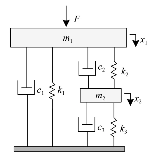
Fig. 2 Schematic diagram of a soil-landmine resonance system model
According to linear vibration theory,

whereXis the displacement matrix,X=diag(x1,x2);andare the corresponding matrixes of velocity and acceleration, respectively;Mis the mass matrix,M=diag(m1,m2);Cis the damping coefficient matrix,Kis the rigidity coefficient matrix,andFis the incident force matrix, whereF=diag(F, 0).
According to Ref.[12], when the soil’s surface is excited by the incident sound wave, the expression for the amplitude-frequency function of surface vibration velocity over buried landmine can be described as:


According to Eq.(2), the numerator and denominator of the transfer functionH(ω) are cubic and quartic polynomials ofω2respectively. That is, there are three zeroes and four maxima, which correspond to the anti-resonance frequency and resonance frequency of the soil-landmine system, respectively.Its physical significance is as follows: when the frequency of the external excitation signal is equal to the anti-resonance frequency of the soil-landmine system, an anti-resonance phenomenon will occur.The speed response ofm1has a minimum (it will not be 0 under damping), and therefore the soil’s vibrational velocity is lower with landmines than without landmines. When an external excitation frequency signal is equal to the resonance frequency of the soil-landmine system, the resonance phenomenon will occur, and the speed response ofm1will have a maximum (it will not be infinite under the action of damping), and the result is that the soil vibration velocity with a landmine is far greater than without a landmine. The soil-landmine system will present complicated resonance and anti-resonance phenomena when being stimulated with sound waves ranging from low to high frequency, resulting in abnormal and unique changes in the vibrational state of the surface. In addition, anti-resonance is only a local phenomenon of the soil-landmine system, while resonance is a global phenomenon. Therefore, vibration in the soil surface above a landmine is greater than in the soil background when the system is excited by sound waves.
2.3 Experimental system of acoustic-to-seismic coupling landmine detection
When sound energy is coupled into underground soil and propagates in the form of seismic waves, it causes vibrations in the soil particles on the surface. These vibration signals can be detected by high-precision laser vibrometers (such as a laser Doppler vibrometer, a radar Doppler vibrometer, a laser self-mixing vibrometer, etc.), in order to obtain the information of vibration velocity, acceleration or displacement. By accurately detecting the difference in surface vibration between landmine and landmine-free fields, the location of a landmine can be determined.
Fig.3 shows the schematic diagram of the experimental system for acoustic-to-seismic coupling landmine detection, which consists of an acoustic emission component and a surface vibration signal acquisition and processing component. The acoustic emission component is mainly composed of a signal generator and an acoustic emission unit. The signal generator is used to control the type and frequency of the output signal. The acoustic emission unit is used to excite seismic waves which mainly includes a high-power speaker and a parametric acoustic array (PAA) device, both of them have their own characteristics and applicable environments. The high-power speaker is low in cost and can emit high-intensity sound waves for better detection. However, the output sound is very loud,which is harmful to the auditory system of the operator. In addition, a high-power speaker is bulky and heavy, which is not portable, and needs to be equipped with external power amplifier equipment.A PAA is a kind of acoustic emission device that can emit high-direction and low-frequency sound waves. Compared with a high-power loudspeaker, a PAA is not only simple to operate, but is also lightweight, does not need an external power amplifier,and is significantly more portable. However, at present, the energy conversion efficiency of a PAA is low, and its output sound energy is usually lower than that of the high-power speaker. The surface vibration signals acquisition and processing component mainly includes a laser vibrometer, data acquisition system and computer. The laser vibrometer detects the surface vibration signals accurately, and the detected vibration signals are inputted to the computer for further processing through the data acquisition system.
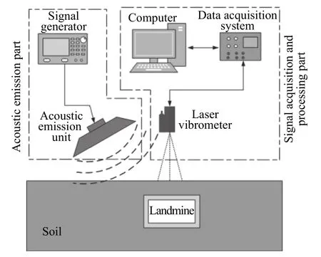
Fig. 3 Schematic diagram of acoustic-to-seismic coupling landmine detection experimental system
3 Laser measurement techniques for surface vibration
According to the descriptions above, accurate detection of the acoustically induced surface vibration is the key technology for acoustic landmine detection. The following sections focus on some existing non-contact laser vibrometers.
3.1 Laser Doppler Vibrometer
A Laser Doppler Vibrometer (LDV) is a noncontact optical sensor that measures surface vibration velocity. The LDV emits laser beams onto the vibrating surface of the ground, and portion of the reflected beams from the measured surface reflect along the opposite path back into the LDV. The surface vibration causes the doppler frequency shift the reflected laser beam. After frequency modulation,the Frequency-Modulated (FM) signal returned from the measured surface carries information about the vibration velocity of the measured surface and is detected by an internal photodetector. After FM demodulation of the detector, the output signal voltage is proportional to the measured surface’s instantaneous velocity[28-31]. As shown in Fig.4, a typical acoustic landmine detection system based on LDV is equipped with a CCD camera and X-Y scanning mirrors, which are used to deploy laser beams horizontally and vertically, respectively. A PC monitoring system displays the surface images.
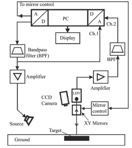
Fig. 4 Typical set-up of the acoustic landmine detection system based on LDV[30]
3.1.1 Single-beam LDV
Fig.5 (Color online) and Fig.6 (Color online)show the results of the acoustic landmine detection experiment based on the single-beam LDV from Ref.[30]. Before scanning the vibrating ground surface, the single-beam LDV (stop-stare laser beam mode) defined the measurement grids and overlaid them onto the ground image. On the image, the intersection of the grid lines represents the precise location of the laser beam on the ground. Fig.5(a) illustrates a grid definition covering a scanned patch of 30 by 30 cm (spatial resolution: 0.97 cm), and the dotted line in the circle indicates the location of a PMA 3 anti-personnel landmine which was buried 2.5 cm deep. During acoustic excitation, the singlebeam LDV detected each point of predefined grids covering the rectangular area. Through the data acquisition channel, the magnitude spectrum of each point can be obtained after applying a Fourier transform. The measured magnitude spectra on pointsA,B,C, andDare illustrated in Fig.6. The magnitude values are evaluated over all of the grid points. The results can be processed to form a two-dimensional(2-D) color map as shown in Fig. 5(b) and a threedimensional (3-D) color map as shown in Fig.5(c)[30].
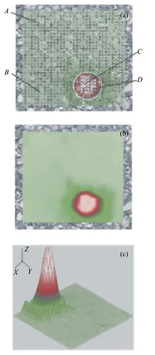
Fig. 5 Experimental measurement results based on a single-beam LDV[30]. (a) A scanned patch of 1 m ×1 m. (b) 2-D color map. (c) 3-D color map.
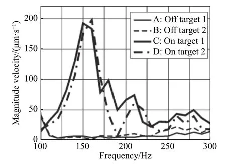
Fig. 6 Measured magnitude spectra of velocity functions at points A, B, C and D from Fig. 5(a)[30]
3.1.2 Moving beam LDV
In another experiment as described in Ref.[32], in order to improve the scanning speed, the continuously-moving beam LDV system installed on a fixed platform was tested in the field. In the experiment, the instantaneous velocity of the ground vibrations from acoustic excitation was measured while the laser beam moved continuously along the trace shown in Fig.7. The continuous motion of the laser beam was limited to a rectangular area of a certain size. The scanning time of the moving beam technique depends on the motion speed of the laser beam and the frequency resolution of the system. As long as the laser beam moves at a reasonable speed,the results measured with a moving beam LDV are comparable to those measured with a single-beam LDV. Fig.8 (Color online) illustrates the scanning results of the single-beam and moving-beam LDVs over a VS 2.2 anti-tank landmine buried 2.5 cm deep. Fig.8(a) illustrates the scanning results of the single-beam LDV, while Fig.8(b)-(d) respectively correspond to the scanning results of the moving beam LDV at moving speeds of 0.4 m/s, 0.8 m/s and 1.6 m/s. It can be seen that as the moving speed increases, the image resolution gradually decreases. In fact, a significant increase in detection speed may result in a decrease in detection probability[32].

Fig. 7 Trace of a moving beam when scanning an area[32]
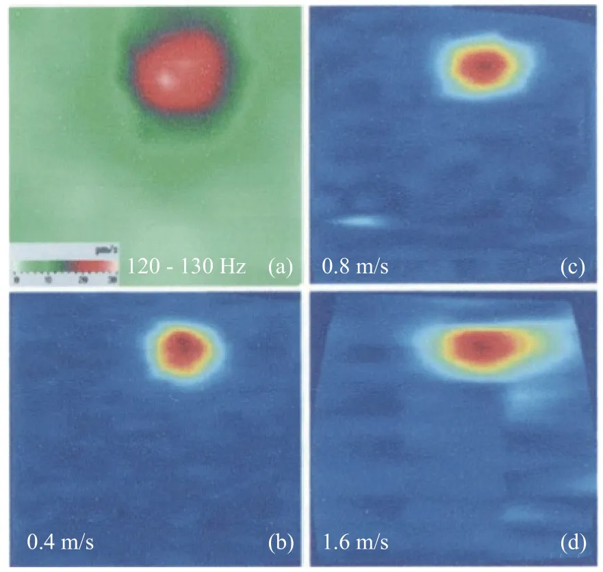
Fig. 8 Scanning results of the single-beam LDV (a) and the moving beam LDVs[32] at 0.4 m/s (b), 0.8 m/s(c), and 1.6 m/s (d) moving speed
3.1.3 Multi-beam LDV
Using a multi-beam LDV can significantly shorten the measurement time[33-35]. A multi-beam LDV emits 16 beams to the ground simultaneously and measures the instantaneous vibration velocity of 16 points at the same time. The 16 beams are evenly distributed on a 1-meter line, and the displacement sensitivity of each beam is greater than 1 nanometer.With all 16 beams traversing the testing area, the multi-beam LDV can work in a continuous scanning mode, and the surface area of 1 square meter can be scanned within 20 seconds as reported in Ref.[35]. The detailed introduction to the principle of the multi-beam LDV vibration measurement has been illustrated in Refs. [33-34], which can be summarized as follows. The diode-pumped solid-state laser is divided into an object beam and a reference beam by a polarizing beam splitter (PBS) cube, and the reference beam produces a frequency offset of 100 kHz through a pair of opposite Acousto-Optic modulators (AOMs). The object beam and the reference beam are split into 16 object beams and 16 reference beams by the same diffractive optical element (DOE). The 16 object beams are focused on a target along a line, and the beams reflected from the target are optically mixed with the reference beams to produce 16 FM signals. The frequency deviation(Doppler shift) of each signal is proportional to the vibration velocity of the target at the measurement point. The FM signals are detected by 16 separated fiber-coupled detectors to obtain the target vibration velocity of each beam. In Ref. [35], a multibeam LDV was used to detect the ground vibration signals, with a system whose schematic diagram and physical diagram are shown in Fig.9. The experiment used pseudo-random noise for excitation, and the multi-beam LDV scanned the landmine at different scanning speeds, ranging from 5 cm/s to 100 cm/s.Fig.10 (Color online) shows two-dimensional images obtained at different scanning speeds. Due to the influence of the dynamic speckle, it can be seen that as the multi-beam LDV scanning speed increases, the amount of speckle noise gradually increases.
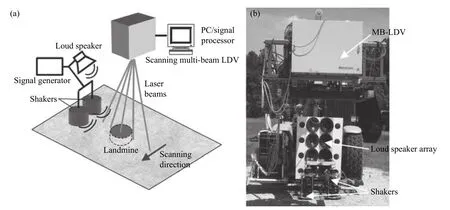
Fig. 9 Multi-beam LDV[35]. (a) Schema of the experimental setup. (b) Multi-beam LDV mounted on a forklift.

Fig. 10 Anti-tank landmine VS2.2 buried 15 cm deep at different scanning speeds[35]. (a) 10 cm/s. (b) 20 cm/s. (c) 50 cm/s. (d)100 cm/s.
Subsequently, MetroLaser developed a new type of MB-LDV that is more compact and can output up to 31 beams, greatly improving the detection efficiency of the system[36]. In addition, the Matrix Laser Doppler Vibrometer (MX-LDV) has been developed, which generates 16×16 beam arrays within a square meter range. By extending the system from a one-dimensional array to a two-dimensional matrix, the vibration measurement efficiency can be greatly improved and the measurement time can be significantly shortened[36-37].
Scanning speed is limited by spatial resolution and frequency resolution when the multi-Beam LDV is used to scan the ground. To overcome this limitation, researchers at the University of Mississippi multiplexed several beams to cover the same area, meaning that they incorporated time Division multiplexing (TDM) of multi-beam LDVs to improve scanning speed[38-39].
3.2 Electronic speckle pattern interferometry
The electronic speckle pattern interferometry(ESPI) technique for vibration measurement uses scattered light on the surface of the measured object to interfere with reference light to generate a speckle image. When the surface of the measured object vibrates slightly, the optical path difference between the speckle and the reference light changes, and the output interference fringes will also move accordingly. By analyzing the output interference fringes,the minute vibration displacement signal of the particles on the test surface can be obtained[40-43].Under the excitation of seismic waves, landmines exhibit multi-modal modes[10]. To fully detect the multi-modal modes of landmines, millimeter-level spatial resolution is required. LDV cannot achieve the required spatial resolution, especially when used with a high measurement speed, but electronic speckle interferometry meets these high spatial resolution and short measurement time requirements.Fig.11 shows the schematic diagram of ESPI vibration measurement. A laser beam is divided into a target beam and a reference beam. After the target beam is scattered and returned by the surface of the vibrating object, its phase changes and it interferes with the reference beam at the CCD camera to produce an interference pattern, that is, a speckle pattern. By analyzing the pattern, the vibration information of the target object can be obtained.
In Ref.[44], the authors used a double-pulse ESPI system to measure ground vibrations. The system obtains two speckle images of the vibrating object by sending two laser pulses synchronized with the vibration peak and the vibration valley one after another, and then uses the phase shift technique to calculate the displacement of each point of the vibrating object between the two pulses. The experimental system is shown in Fig.12. The system mainly includes a double-pulse ruby laser, a CCD camera, and a computer. During the experiment, an electromagnetic vibrator was used to excite vibration in the sand box, and the signal generator was used to drive the vibrator through a power amplifier and provide a synchronization signal for the laser.The laser Doppler vibrometer is used to measure the resonance frequency of the buried mine. After the resonance frequency is determined, a sinusoidal signal of that frequency is used to drive the vibrator,and the ESPI system is used to capture the vibration image of the ground above the landmine.

Fig. 11 Schema of ESPI for measurement of out-of-plane vibrations[44]
Fig.13 (Color online) shows spatial maps(fringe pattern and grayscale image) of the vibrating surface over a VS 1.6 antitank landmine and a VS 50 antipersonnel landmine buried 4 cm deep.The ESPI system can draw a spatial map of the surface vibration above the buried landmines with a high spatial resolution within no more than half a vibration cycle, and the minimum detectable amplitude is about 0.1 μm peak-to-peak[44].
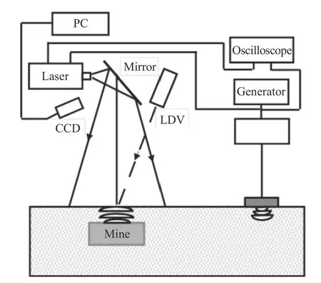
Fig. 12 Diagram of the experimental setup based on ESPI[44]
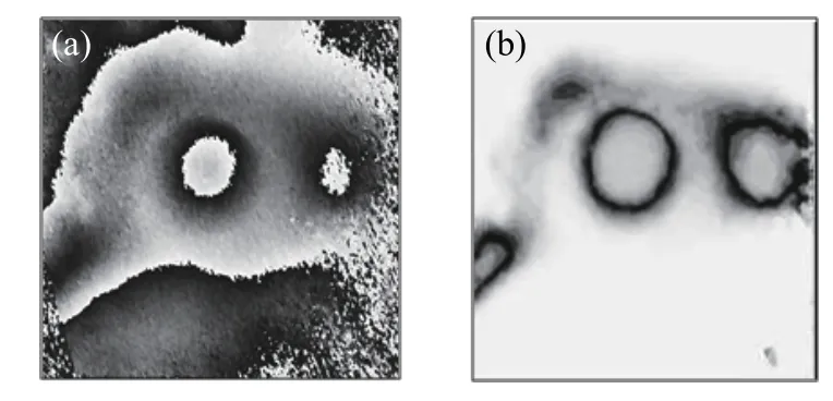
Fig. 13 Spatial maps of buried landmines[44]. (a) Fringe pattern. (b) Grayscale image.
3.3 Laser self-mixing vibrometer

Fig. 14 Schematic diagram of the laser self-mixing vibrometer
The measurement principle diagram of the laser self-mixing vibrometer is shown in Fig.14. The semiconductor laser encapsulates a photodiode inside itself to monitor light power, so it acts as both a light source and a detector[45]. After the laser beam emitted by the semiconductor laser is reflected or scattered on the surface of a vibration target (such as ground surface and landmine shell), a small part of the reflected or scattered light carrying the vibration information is fed back to the cavity and gets selfmixed with the original light so that the output optical power of the laser changes regularly. The vibration information of the target can be obtained by analyzing the change of the output optical power detected by the photodiode in the laser[46-49].An experimental model of acoustic-to-seismic coupling landmine detection based on a laser selfmixing vibrometer was proposed in Ref. [50]. The laser self-mixing vibrometer was used for an acoustic-to-seismic coupling landmine detection experiment. Three types of landmines (Type 72 AT landmine, Type 69 AT landmine and Type 69 AP landmine) and a brick were buried in the sandpit, with a burial depth of 4 cm, placed as shown in Fig.15.Sound waves with a swept-frequency of 80~450 Hz were used for excitation, and the testing area was scanned by a laser self-mixing vibrometer. The resulting three-dimensional and two-dimensional images are shown in Fig.16. Three light points in Fig.16(a) represent the presence of the three landmines, while pointsAandBrepresent the AT landmines andCrepresents the AP landmine. The experimental results have demonstrated the feasibility of acoustic-to-seismic coupling landmine detection by using a laser self-mixing vibration measurement technique.

Fig. 15 Position of buried objects[50]

Fig. 16 Color maps of the test-bed[50]. (a) Two-dimensional (2D) color map. (b) Three-dimensional (3D) color map, derived from (a).
3.4 Summary of the above laser vibrometers
According to the descriptions above, the characteristics of the LDV, ESPI and laser self-mixing vibrometer can be summarized as shown in Table 1.
The advantages and disadvantages of them can be summarized as shown in Table 2.

Tab. 1 Characteristics of the above laser vibrometers

Tab. 2 Advantages and disadvantages of the above laser vibrometers
As a result, although the non-contact sensors currently researched have their own characteristics,they are not well qualified for the detection of weak and complicated surface vibration signals due to their limitations in reliability, rapidity, portability, etc.
4 Electronic speckle-shearing pattern interferometry
4.1 Concepts and characteristics
Electronic Speckle-Shearing Pattern Interferometry (ESSPI) is a new technique developed to measure displacement derivative. The phase change in the fringe is proportional to the derivative of the out-of-plane displacement caused by the surface vibration and deformation. The fringe series reflects the change of the displacement gradient, and the magnitude of the change of the displacement gradient reflects the magnitude of the deformation caused by the vibration. Therefore the deformation caused by the vibration can be determined by observing the change in the fringe series[51]. ESSPI differs from electronic speckle interferometry in its optical structure, while the subsequent image processing system is the same. In addition to sharing many advantages with electronic speckle interferometry, ESSPI also has a simple optical path and low requirements for vibration isolation. In addition, it measures displacement derivative, which is very sensitive to the strain concentration of a defect load while automatically eliminating rigid body displacement, so it is widely used in the field of non-destructive testing (NDT).Laser speckle-sharing pattern interferometry means that the laser light source illuminates the surface of the measured object with diffuse reflection, and the reflected light enters the shearing element. The shearing element is composed of a beam splitter, a plane mirror parallel to the beam splitter, and a shearing mirror with a small tilt angle to the beam splitter. After passing through the beam splitter, the light is divided into two beams of equal energy. One beam is incident on the plane mirror, and the other beam is incident on the shear mirror with a certain tilt angle. After the two reflected beams pass through the beam splitter, an original image and a sheared image that is misaligned with the original one are formed to show interference on the imaging plane, thereby forming an image of a sheared speckle interference fringe[52-54].
In this paper, a new method for measuring the weak vibrations of the ground’s surface is proposed by combining acoustic-seismic coupled landmine detection technology and ESSPI technology. The high-energy sound wave pulse is used to excite vibration near the landmine, which causes abnormal changes of the state in ground vibrations from the landmine’s resonance. The laser beam is projected to the measured position of the buried landmine, and the speckle interference fringes containing ground vibration information are recorded in real-time by a high-resolution CCD camera system. By analyzing the interference fringes, the weak vibration signals of the ground surface can be obtained, and the existence of a buried landmine can be determined.Through an in-depth study of the vibration characteristics of landmines, the existence of buried landmines and other buried information can be accurately and quickly identified.
4.2 Preliminary experiment and result analysis
The acoustic-optic landmine detection experimental system based on ESSPI built by the author’s research group is shown in Fig.17. The detection target was a Type 69 anti-tank plastic landmine buried in sand with a depth of 2 cm, as shown in Fig.18(a). Before taking the image, the resonance frequency of the buried plastic landmine was determined by setting the laser self-mixing vibrometer frequency to 110 Hz. Therefore, a sinusoidal signal with a frequency of 110 Hz was used for sound excitation. The ESSPI system was used to detect surface vibrations, and the experiment was initially conducted. The experimental results are shown in Fig.18(b)~18(d) (Color online). It can be seen that the surface area where the landmine is buried exhibits obvious interference fringes, but no fringe appears in the surface area where the landmine is not buried. The fringes appearing are butterfly-shaped.The size of the interference fringe pattern is 2 452 pixel×2 056 pixel, the fringe image resolution is 0.1~0.2 mm/pixel, and the interference fringe pattern is displayed in real-time during the experiment. By adjusting the intensity of the acoustic excitation and observing the change in interference fringes as shown in Fig.18(b)~18(d), it can be seen that when the decibel level of the sound is 100 dB, the fringe has 5 levels; when the decibel level is 95 dB, the fringe has 3 levels; when the decibel level is 90 dB,the fringe has about 1 level. It can be inferred that due to the reduction of the excitation sound wave energy (decrease in decibel level), the amplitude of the surface vibration decreases, that is, the relative deformation of the surface decreases, and the change in the displacement gradient decreases,which causes the number of interference fringe levels to decrease accordingly. The experimental results preliminarily prove the feasibility of acoustic-optical landmine detection based on ESSPI.

Fig. 17 Experimental system of acoustic-optic landmine detection based on ESSPI
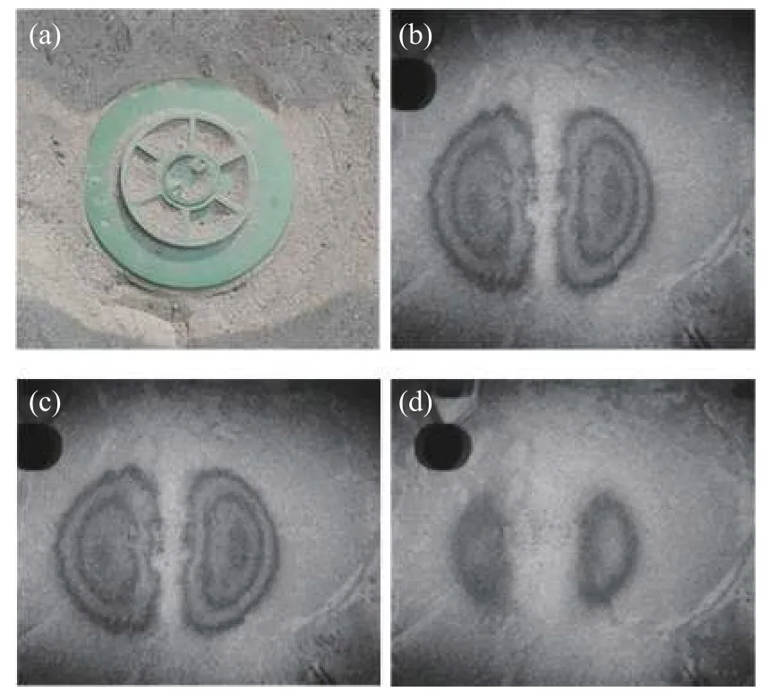
Fig. 18 Interference fringes at different decibel levels. (a)Type 69 anti-tank plastic landmine. (b) Interference fringe at 100 dB. (c) Interference fringe at 95 dB. (d) Interference fringe at 100 dB.
5 Conclusion
Based on the analysis of acoustic-to-seismic coupling landmine detection technology, this paper summarized the principles of the existing non-contact laser vibration measurement techniques and their applications in landmine detection. The characteristics of the existing laser vibration measurement techniques used in acoustic-to-seismic coupling landmine detection were analyzed. The feasibility of electronic speckle-shearing pattern interferometry in acoustic-to-seismic coupling landmine detection was demonstrated by the preliminary experiment. It can be concluded that non-contact laser vibration measurement techniques have great accuracy and real-time performance, and have achieved great results in surface vibration signal detection. However,the current laser vibration measurement techniques(laser Doppler interferometry, electronic speckle interferometry and laser self-mixing interferometry)used for surface vibration detection have defects such as having too long of a scanning time, poor portability, insufficient sensitivity and spatial resolution. Electronic speckle-shearing pattern interferometry can be used to detect surface vibration signals accurately and quickly. It also has advantages such as its simple light path and low requirements for vibration isolation, which is more suitable for research in practical landmine detection systems. Experiments and theoretical analyses under various conditions will be conducted in the future to further study acoustic-to-seismic coupling landmine detection technology based on electronic speckle-shearing pattern interferometry technique.
