Double-dot interferometer for quantum measurement of Majorana qubits and stabilizers*
2021-01-21KaiZhou周凯ChengZhang张程LupeiQin秦陆培andXinQiLi李新奇
Kai Zhou(周凯), Cheng Zhang(张程), Lupei Qin(秦陆培), and Xin-Qi Li(李新奇)2,,‡
1Department of Physics,Beijing Normal University,Beijing 100875,China
2Center for Joint Quantum Studies and Department of Physics,School of Science,Tianjin University,Tianjin 300072,China
Keywords: Majorana qubits,stabilizers,quantum measurements
1. Introduction
In the past years, searching for Majorana zero modes(MZMs)in topological superconductors has become an active field in condensed matter physics.[1–4]Among the various efforts, the scheme based on semiconductor nanowires has received particular attention because of the relative ease of realization and control.[5–10]The key signatures of MZMs found in the experiments are the zero-bias conductance peaks in tunneling spectra.[5,7,10]
Beyond the problem of MZMs detection, it can be expected that the nanowire based experiments will soon move to a more advanced level,e.g.,demonstration of non-Abelian statistics and validation of a prototype topological qubit. The latter may include measuring the topological-qubit coherence time,the residual MZM splittings,and quasiparticle poisoning rates.All of these can be extracted from the quantum measurements of a Majorana qubit.
An even more advanced level of study is the fault-tolerant quantum computation,in which the surface-code architectures are recognized as very powerful platforms.[11]In particular,it has been recognized that the Majorana surface code architecture based on two-dimensional networks of nanowire MZMs holds key advantages in both the hardware realization and the actual operation of the code.[12,13]In this context, quantum measurements of the so-called stabilizers in the surface code are the most important procedures,which project the system to a well-defined code state and are employed for error detection and correction to realize fault tolerance in quantum operations.
In this work, we focus on analyzing the measurement performance of a double-dot interferometric device shown in Fig. 1, which can be used for quantum measurement of both Majorana qubits and stabilizers. In this set-up, the Majorana island is coupled via two quantum dots to the transport leads.The interferometric device consists of two transmission paths,say, a direct link between the two dots and the other one for electron flowing through the Majorana island. The loop of interference enclosed by the two paths is pierced by an external magnetic flux(φ). Via properly tuning the magnetic flux,the different eigenvalues ±1 of the Majorana qubit or stabilizer will result in different measuring currents.
For Majorana qubits, in order to overcome limitations from parity conservation, we consider a 4-MZMs qubit as shown in Fig. 1(b). This Majorana box qubit (MBQ) was recently described by Plugge et al.[14]For Majorana stabilizers, we illustrate schematically in Fig. 1(c) a concrete 8-MZMs plaquette, which was proposed in Refs. [12,13] in the nanowire-based Majorana surface codes. Its measurement protocol was also proposed,say,via a quantum interferometry by point contact measurements of the linear conductance.
In this work, based on similar ideas we consider a specific set-up where the Majorana island is coupled via quantum dots to the transport leads. The main motivation of introducing quantum dots in the interferometer set-up is as follows.(i)It allows us to account for the full multiple tunneling process between the two dots through the Majorana island,[15]within a master equation approach. If restricted in the lowestorder co-tunneling regime,which results in a Majorana-islandmediated effective coupling between the dots,the master equation approach allows us to obtain analytic solutions for the measurement currents,even in the presence of decoherence effects. (ii)The gate-controlled hybrid nanowires and quantum dots are becoming very important platforms for Majornana verification[16–20]and quantum computation.[13]For instance,in the recent experiments,[19,20]the gate-controlled coupling structure of a nanowire and a quantum dot was developed to probe the sub-gap Majorana states via an improved technique of tunneling spectroscopy. (iii) Importantly, differing from most other quantum interferometers, we will see that for our proposed set-up, decoherence arisen from the dot-level fluctuations does not seriously degrade the quality of measurement. Under some parametric conditions, stronger decoherence of this type can even enhance the measurement visibility,quite outside a simple expectation. (iv) Finally, introducing the quantum dots in Fig.1 may benefit protecting the Majorana island from quasiparticle poisoning(e.g.,at finite temperature environments and finite bias voltage of transport),compared to directly coupling the island to the continuum reservoirs/leads.

Fig. 1. (a) Schematic plot of the double-dot interferometer for quantum measurements of Majorana qubits and stabilizers. Inside the transport setup(with lead-reservoirs R1 and R2), the double dots are tunnel-connected through two channels: a direct link shown in the figure; and the other one through the Majorana island in between ports 1 and 2. The two channels form an interference loop through which a magnetic flux φ can be pierced.(b) A typical four Majorana-zero-modes qubit, built with two topologicalsuperconducting wires (green) shunted by a conventional superconductor bridge(orange). (c)Example of a Majorana stabilizer designed in the Majorana surface codes. The 8 Majoranas result in an effective code operator ˆZ =∏8j=1 γ j = ˆz1ˆz2ˆz3ˆz4,with the eigenvalues Z=±1 to be determined by the quantum measurement.
The paper is organized as follows. In Section 2, we present the model description and transport master equation approach for the double-dot interferometer,by considering to insert the Majorana qubit/stabilizer into one of the interfering arms(while remaining the derivation of the Majorana-islandinduced effective coupling in Appendixes A and B). In Section 3, we obtain the analytic solution for the measurement currents and compare it with the numerical result from the full 12-state model of Majorana qubit. We further analyze the decoherence effect in Section 4 and will pay particular attention to the unusual feature owing to the dot-level fluctuations,which would result in different behaviors rather than the usual‘which-path’ dephasing. We fianlly summarize the work in Section 5.
2. Model and methods
2.1. Set-up description
The double-dot interferometer we propose is schematically shown in Fig. 1, where a Majorana island is inserted in one of the interference paths while the other path is a direct tunnel-link between the dots. The two quantum dots are further coupled to transport leads. As usual,the interference loop enclosed by the two paths is pierced by an external magnetic flux φ.The phase-sensitive transport current between the leads can reveal the state of the Majorana island.Here,the Majorana island can be either a basic qubit or a surface-code stabilizer.As explained in the introduction, for the former, we consider a 4-MZMs qubit as shown in Fig.1(b), which is built by two topological superconductor nanowires shunted by a conventional superconductor.[14]For the stabilizer, we consider a 8-MZMs plaquette, which was proposed in Refs.[12,13]in the nanowire-based Majorana surface codes.
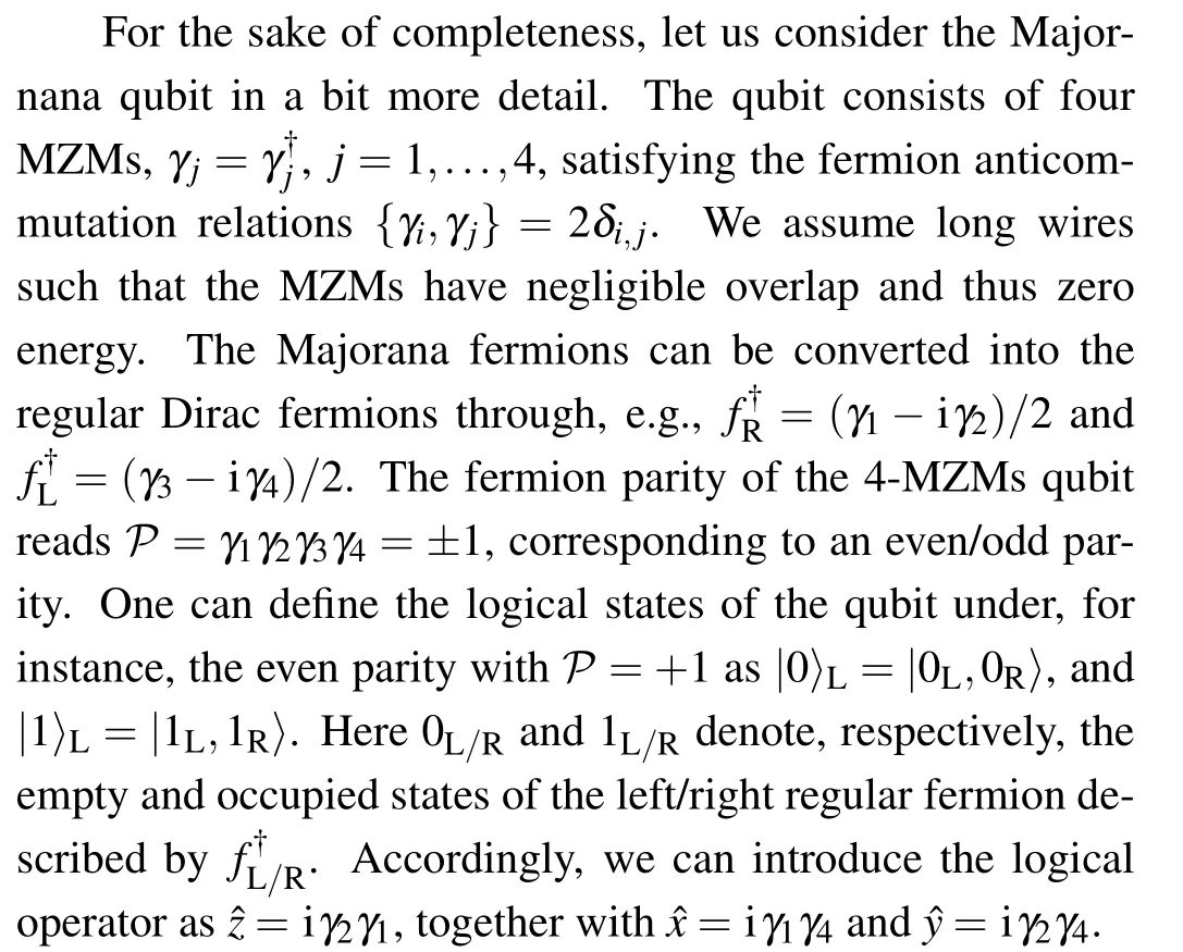
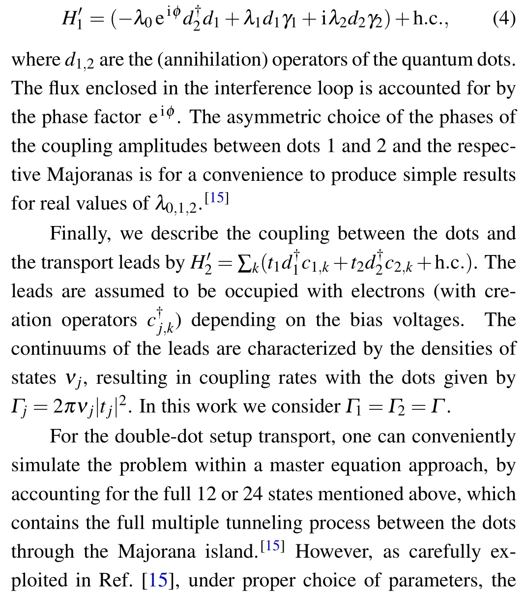
In order to prevent the qubit from quasiparticle poisoning, an important design is building a small floating Majorana island with large charging energy EC. The Coulomb interaction Hamiltonian is phenomenologically given by HC=EC(N-ng)2,with N the total charge on the floating island and ngthe gate charge which depends on the gate voltage and gate capacitance. To minimize the charging energy, the optimal choice is a symmetry point with an integer value of ng. More explicitly,we may denote the logical states of the qubit as
Here n0denotes the number of Cooper pairs. The total charge N is conserved on the qubit Hamiltonian level but varies during the transport measurement process. That is, a single electron is allowed to virtually enter or leave from the island. For the|0〉Lsector,the relevant states include

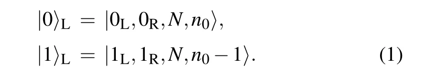
Similarly,for the|1〉Lsector,the states include
For the setup shown in Fig. 1, the ‘central system’ of transport includes also the two quantum dots, which are assumed with strong on-site Coulomb interaction allowing each dot to be empty or singly occupied. We thus have 4 dot basis states|0,0〉, |0,1〉, |1,0〉, and |1,1〉. Hence, the total set of basis states of the central system are 12 product states formed by the 4 dot states and the 3 states of the Majorana qubit island for each of the|0〉Land|1〉Lsectors.
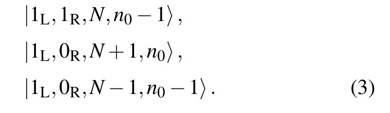
The tunnel coupling between the dots and Majorana qubit is described by[15]
2.2. Master equation approach
For quantum transport, the master equation approach is a very convenient tool. From the perspective of quantum dissipation, the transport leads can be regarded as a generalized fermionic environment, and the system of interest is the central device, e.g., the Majorana island plus the two quantum dots in our case. For weak coupling between the central system and the transport leads, under the Born approximation,the so-called Born–Markov–Redfield master equation for the reduced state of the central system reads[15,21,22]
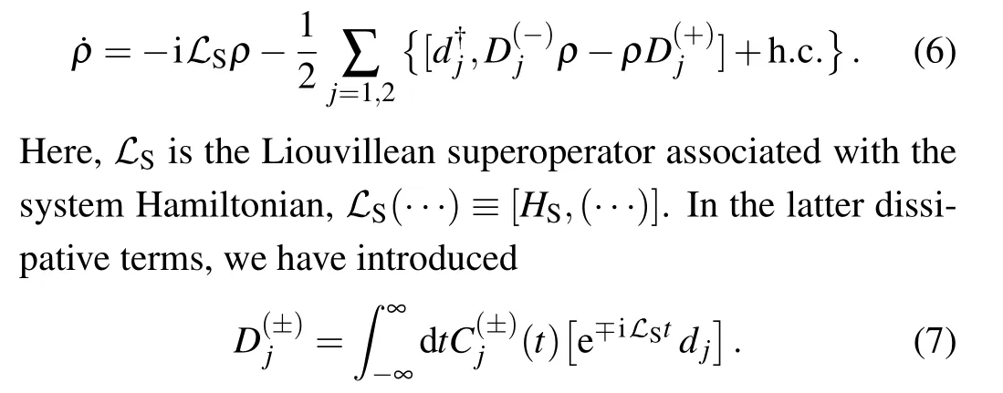
The reservoir correlation functions are defined from the respective local-equilibrium thermal averages of the reservoir operators

Here we may mention that,in addition to a convenient calculation of the stationary current,the master equation approach allows calculating the time-dependent currents much more conveniently than the Green’s function method and the Landauer–B¨uttiker scattering approach.
3. Measurement currents
To obtain explicit solutions, let us convert the operator form of the master equation into a matrix-elements form, by using the state basis of the system Hamiltonian HS. The most convenient choice of the state basis is the number states of occupation of the double dots, i.e., |1〉 = |00〉, |2〉 = |01〉,|3〉=|10〉, and |4〉=|11〉. Here we only consider single occupation of each dot, owing to the strong Coulomb blockade effect. Also,the explicit occupation states of the Majorana island are not needed,since we would like to adopt the description of the Majorana-mediated effective coupling between the dots,given by Eq.(5).

In Fig.2,we display the steady-state currents of measurement. The quantum interference leads to a phase shift of π between the currents for the Majorana qubit states z=±1. The effects of various parameters have been investigated in detail in Ref.[15],while here we only show the effect of the offset δ of the dot levels. In Fig.2, we compare the results from several solving methods, say, the analytic solution (solid lines),the numerical result (circles) from the effective coupling (4 states)model,and the numerical result(dashed lines)from the full 12-state model. We find the results in satisfactory agreement.
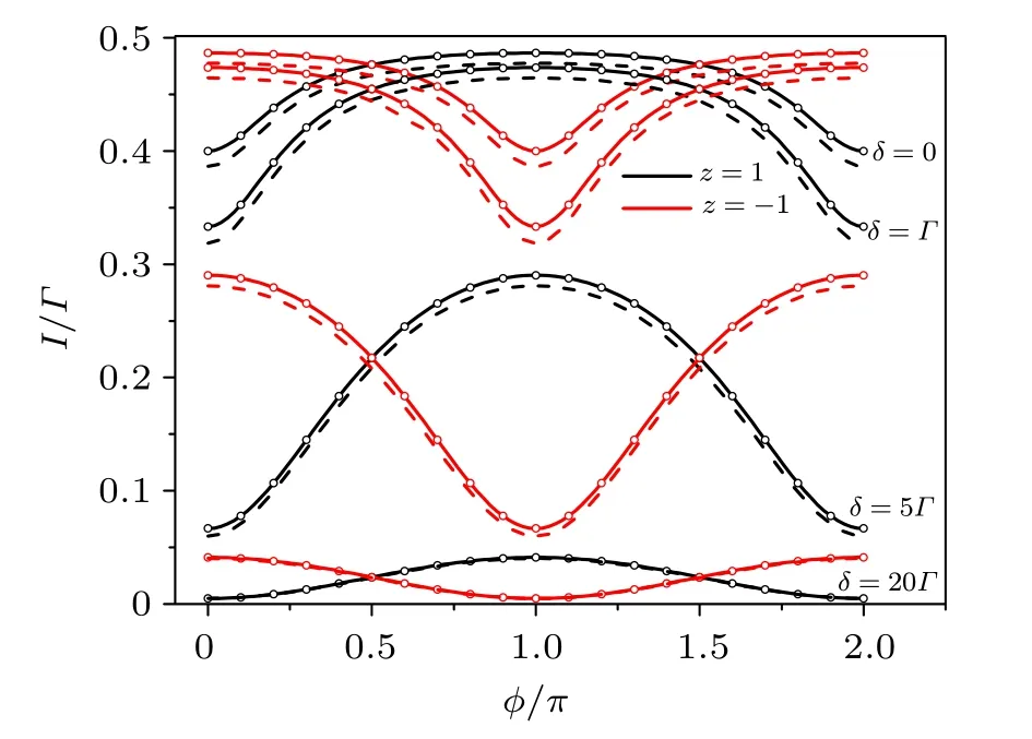
Fig. 2. Measurement currents in steady state for the distinct states z=±1 of the Majorana qubit. The interference effect is manifested through the dependence on the enclosed magnetic flux. The currents for z=±1 differ by a phase shift of π. The interference pattern is also sensitive to the offset δ of the dot levels. In the plot we compare results from several solving methods: analytic solution (solid lines), numerical result (circles) from the effective coupling (4 states) model; and numerical result (dashed lines) from the full 12-state model. The parameters we used are Γ1 =Γ2 =Γ =0.01, EC =100Γ, λ0 =Γ, and λ1=λ2=10Γ.
Indeed, the 4-state low-energy Hamiltonian can reproduce most results with sufficient accuracy.[15]Differences only arise in some range of parameters, associated with properties of the higher-energy states of the Majorana island.Actually,in the full 12-state description, there are also the 8 high-energy states. The eigenstates are superpositions of the low-energy and the high-energy basis states, and even the low-energy eigenstates have a small, but not exponentially suppressed contribution from the high-energy states and vice versa. In Ref. [15] it was found that the current difference between the full 12-state and effective 4-state treatments becomes pronounced when λ0is large. In this case,the total transmission is enhanced but the interference effect is weakened owing to the unbalanced transmission paths, i.e., λ0≫12. However,after accounting for small finite temperature effect, even this difference will be suppressed.[15]
4. Decoherence effects
For the double-dot interferometer under consideration,the study of decoherence effects can include such as the energy fluctuation of the Majorana island,the quasi-particle poisoning to the Majorana states, and the level fluctuations of the double dots. Owing to the strong Coulomb-blockade effect(large EC), we assume a strong suppression of the quasiparticle poisoning.For the effect of the high-energy-level fluctuations of the Majorana island, the full 12-states simulation(carried out in a separate work)shows a slight reduction of the effective coupling between the dots mediated by the Majorana island. Therefore,in the present work,we would like to focus on the decoherence effects of the double-dot level fluctuations.Again, even in the presence of decoherence, the low-energy effective coupling treatment allows us to obtain analytic solutions.
4.1. Naive average
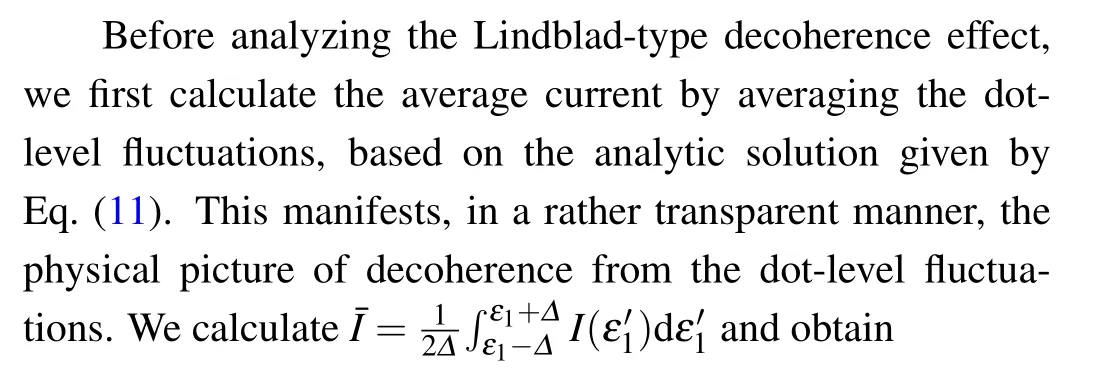
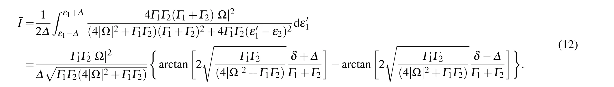

Fig. 3. Average current over an amount Δ of the dot level (ε1) fluctuation. The parameters are assumed as Γ =0.01, ε1 =ε2 =0, λ0 =Γ, and12=2Γ.
In Fig.3 we show the effect of the fluctuation amount(Δ)of the dot level(ε1)on the measurement current.For any given magnetic flux φ, we find that the average current decreases with Δ. The reason for this overall decreasing behavior is the decrease of each individual current along with the increase of Δ,owing to the stronger deviation from the resonant coupling under ε1=ε2. However,the interference pattern does not vanish or even is not reduced (e.g., see the case of Δ =5Γ in Fig.3),unlike the usual decoherence effect in the which-path interferometry set-up. Here,the dot-level fluctuation does not correspond to the effect of the which-path back-action. For each pair of (ε2), an interference pattern is indicated and most importantly,the location of interference extrema of these patterns does not shift with the difference ofand ε2. Therefore, the in-phase summation (and average) of these patterns does not cause cancelation which is actually the origin of the dephasing (decoherence) effect. The naive treatment in this subsection has resulted in a qualitatively similar result as that in the next subsection, using the Lindblad-type decoherence model with constant rate(γ),e.g.,compared with Fig.4.However,it seems not very clear how to quantitatively connect the fluctuation amplitude Δ analyzed here with the decoherence rate γ in the next subsection, despite that for both treatments we can obtain analytic solutions.
4.2. Lindblad-type decoherence
Now we turn to the standard treatment of decoherence originated from the energy level fluctuations of dot 1 with respect to dot 2,under the influence of environment. Under the wide-band limit (Born–Markovian approximation), we only need to modify the transport master equation by adding a new term γD[ˆs]ρ,with γ the decoherence rate andthe decoherence operator. In the same basis for Eq.(10),we have
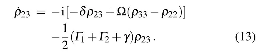
The equations of other matrix elements remain the same as in Eq.(10).
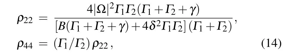
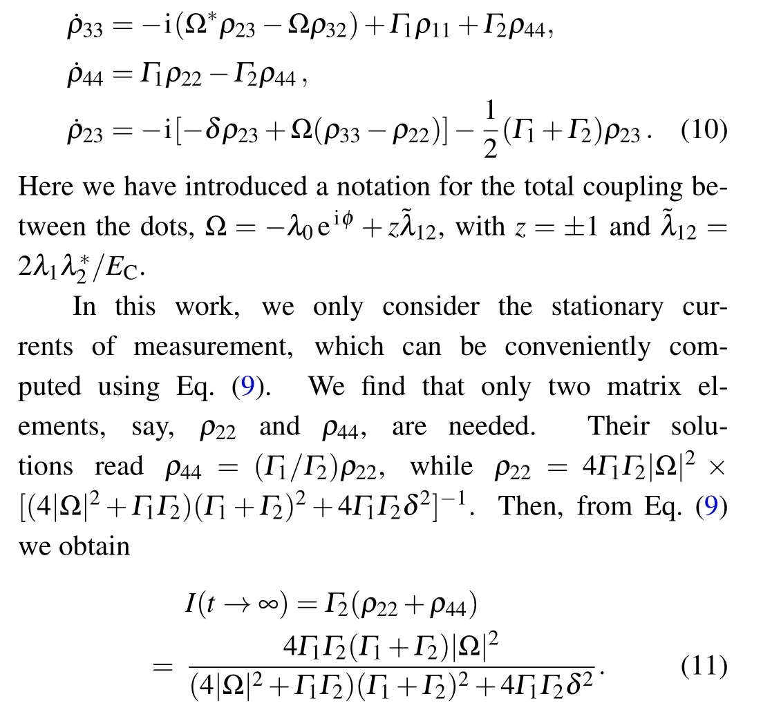
To obtain the steady-state current, we first find the stationary solution of ρ22and ρ44,where we have introduced B=4|Ω|2(Γ1+Γ2)+Γ1Γ2(Γ1+Γ2+γ)to simplify the expression of ρ22.Based on this solution,the steady-state current can be obtained through I=Γ2(ρ22+ρ44),which yields
In Fig. 4 we plot the results based on Eq. (15), showing the decoherence effect (i.e., the dot-level fluctuations) on the current. The effect is qualitatively the same as the Δ-effect(the fluctuating amplitude of the dot level) shown in Fig. 3,despite that γ is determined by the coupling strength to the environment and the density-of-states of the environment. Indeed,γ has the same effect of the level fluctuation amplitude.In Fig. 4 we adopt δ =ε1-ε2=2Γ, i.e., the two dots are not coupled in resonance. We then find the current increasing with the increase of γ in the first stage, owing to better matching of the dot levels caused by the stochastic fluctuations. This behavior is somehow similar to the phenomenon of dissipation-assisted tunneling. However,of course,the current would decrease with the further increase of γ,because of the stronger deviation from resonance.

Fig. 4. Decoherence effect on the measurement currents. For the purpose discussed in the main text,we set a nonzero offset of the dot levels(δ =2Γ).Other parameters are the same as those in Fig.2.
With the help of the analytic solution Eq. (15), we may determine some characteristic values of γ. First, for a given δ, we can find a γ*, which maximizes the current. From the following result:

4.3. Interference visibility
As observed in Figs. 2 and 3, the interference signal of the present double-dot interferometer does not sensitively decrease with the decoherence strength between the two dots.We are thus interested in a more meaningful quantity,say,the visibility of the interference pattern,defined as
where Imaxand Iminare,respectively,the peak and valley values of current oscillation with the magnetic flux φ. Obviously,the larger visibility means a better distinguishability of the qubit states from the quantum measurement. Based on the analytic solution we find
In Fig.5 we show the decoherence effect on the visibility.The most remarkable feature observed here is that the visibility is enhanced (for small level-offset δ) along the decoherence rate γ, which is unusual compared to the decoherence effect in other which-path setups. The basic reason, as mentioned in Subsection 4.1 (associated with Fig. 3), is that the dot-level fluctuation in our double-dot interferometer does not result in the which-path back-action.Moreover,for each‘fluctuating configuration’of the dot-levels,the quantum mechanically implied interference pattern shares the same magneticflux (φ) conditions for constructive and destructive interferences. Then, no decoherence-associated-cancelation occurs in the current. However, the level fluctuations do affect (reduce) the current magnitude (for vanished or small δ), owing to driving the dots further away from the condition of resonant tunnel coupling. Therefore, the interplay between the persistently surviving quantum interference and the levelfluctuation-induced off-resonance transmission results in the enhanced visibility if we increase the decoherence rate γ, as seen in Fig. 5. Similar explanation applies as well to the enhanced visibility by increasing the level offset δ, for a given decoherence rate γ as shown in Fig.5.
More complicated situation occurs if we consider to increase both δ and γ. This will result in the turnover behavior observed in Fig. 5. Based on the analytic result of Eq. (19),we find that the turnover point is given by γ =2|δ|-Γ1-Γ2.Indeed,in Fig.5 we find that for δ >Γ the visibility decreases first, then increases with γ. But for 0 ≤δ ≤Γ, the visibility only increases with γ monotonically.
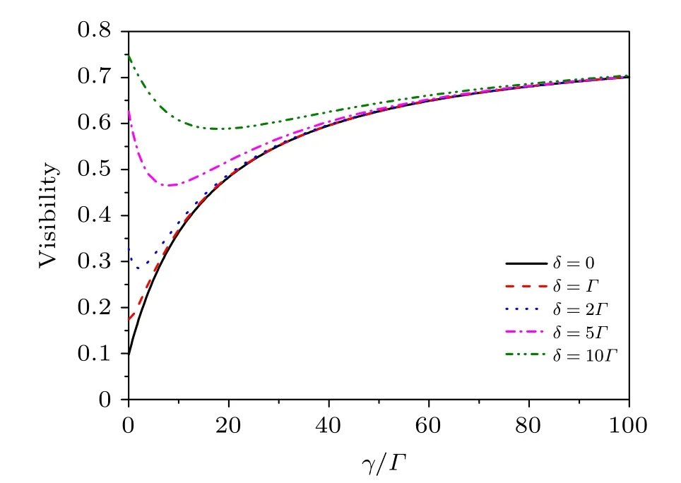
Fig.5. Decoherence effect on the visibility of the interference pattern,e.g.,shown in Fig.4. Results for different offset δ of the dot levels are displayed.A unique feature is the monotonically enhanced visibility(for small δ)along the decoherence rate γ, which is unusual compared to the decoherence effect in the usual which-path interferometry setups. Parameters: Γ =0.01,λ0=Γ,and 12=2Γ.
5. Summary
We have analyzed the performance of a double-dot interferometer,in connection with the quantum measurement of Majorana qubits and surface-code stabilizers. The double-dot design has some advantages such as separating the Majorana island from fermionic environment(thus avoiding quasiparticle poisoning). In the co-tunneling regime (through the Majorana island), the double-dot setup allows an efficient lowenergy effective description for the Majorana-mediated coupling between the dots,and a simple master equation approach allows us to obtain analytic solutions for the transport currents(even in the presence of environment noises). A noticeable feature of the double-dot interferometer is that the dot-level fluctuations do not cause sensitive degradation of visibility of the measurement signals, which is unusual regarding to the decoherence effect in other which-path setups. The results analyzed in this work are expected to be useful for future experiments of Majorana qubit and stabilizer measurements.
Appendix A:Effective coupling mediated by the Majorana qubit
In the Coulomb blockade regime(with large charging energy EC), the electron transmission through the Majorana island as shown in Fig.1 involves only virtual occupation of the island states. In this case,it is desirable to develop an effective description for the Majorana-island-mediated coupling.[13,23]In this appendix,we present a brief derivation for the effective coupling Hamiltonian,Eq.(5).
Let us re-denote the tunnel-coupling Hamiltonian between the dots (D1and D2) and the two Majoranas (γ1and γ2)as
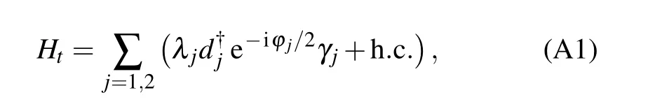
where the coupling amplitude λjand the dot-electron operators are denoted the the same as in Eq. (4). Taking this coupling Hamiltonian as perturbation and applying the 2nd-order perturbative expansion, the transfer amplitude of an electron from D1to D2is give by〈f|HtG0Ht|i〉,where the initial(final)state|i〉(|f〉)corresponds to the electron in the quantum dot D1(D2) and the Majorana qubit island in the same ground state.In the perturbative expansion, G0is the free Green’s function of the Majorana island.
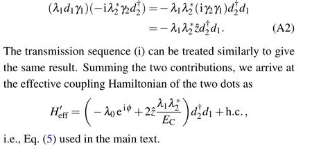
For electron transmission through the Majorana qubit from D1to D2,there are two sequences: (i)first D1→γ1then γ2→D2;(ii)first γ2→D2then D1→γ1. Moreover,both sequences have the same intermediate-state energy offset of EC,which results in an energy denominator-1/ECin the perturbative amplitude (contributed by the free Green’s function).For each transmission sequence, after identifying the energy denominator,one can reorganize the operator orders,under the anticommutation rule of fermions. For instance,one transmission sequence(the second one mentioned above)is accounted for as
Appendix B:Effective Hamiltonians for stabilizers
B1. Effective code Hamiltonian
Following Refs. [12,13], a minimal Majorana stabilizer plaquette involves eight Majoranas(MZMs),as schematically shown in Fig.1(c). The eight Majoranas are contributed from four Majorana islands (not shown in Fig. 1(c)), while the neighboring Majorana islands are linked by tunnel bridges,described by the tunnel-coupling Hamiltonian
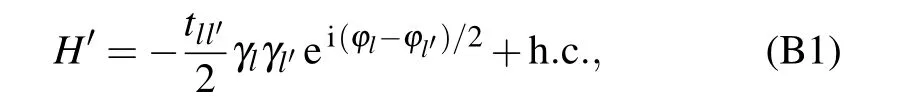
where tll′is the coupling amplitude between the Majoranas γland γl′, and φl(φl′) the respective superconducting phase of the Majorana island l (l′).

B2. Effective coupling Hamiltonian mediated by a Majorana stabilizer
In this subsection we further derive the effective coupling between the two quantum dots mediated by the Majorana stabilizer.To be specific,let us consider an electron transfer from D2to D1. There are two types of paths: one is the shortcut through the connection link between γ2and γ1; the other is along the stabilizer loop,i.e.,(γ2,γ3)→(γ4,γ5)→(γ6,γ7)→(γ8,γ1). The transfer amplitude for the former case is given by the 3rd-order perturbative expansion 〈f|HtG0H′G0Ht|i〉,while for the latter case it is given by the 5th-order expansion〈f|HtG0H′G0H′G0H′G0Ht|i〉. For the sake of seeing more clearly the transfer sequence, let us define the segment operators Lj=d†jγje-iφj/2and Amn=γmγnei(φm-φn)/2,extracted from the tunneling Hamiltonians(A1)and(B1).
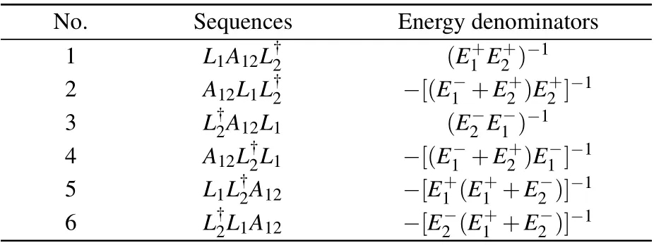
Table B1. All the 6 sequences and energy denominators of an electron transfer through the shortcut of the Majorana stabilizer from D2 to D1 as shown in Fig.1.
(i) For the shortcut case, the transfer process involves each of the operators L1,L†2,and A12once,and there are 3!=6 sequences as shown in Table B1. Summing up all contributions(i.e.,the energy denominators),we obtain[13]
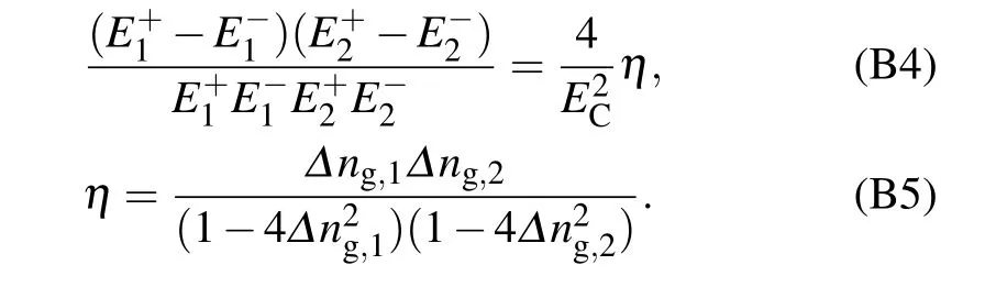
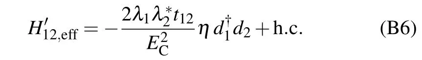
The asymmetry parameter η depends on the charge offset parameters Δng,l=1,2and thus will be negligibly small with vanishing charge offsets. Then,we obtain the effective tunneling Hamiltonian mediated by the shortcut link between γ2and γ1,
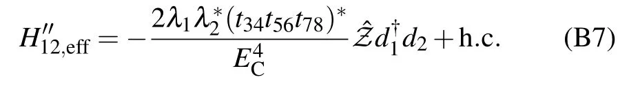
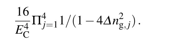
(ii) For the transfer path around the Majorana loop, permutation of the 5 tunnel-coupling Hamiltonians will generate 5!=120 transfer sequences(part of them are illustrated in Table B2). Notice that each sequence would result in the same product of operators, ˆZd†1d2,differing from each other only in amplitude owing to the different energy denominators. Summing up all the energy denominators, we find a very simple factor Ignoring the relative small quantity (Δn2g,j) in the denominators, we obtain the effective coupling Hamiltonian mediated by the Majorana loop
Finally, summing the contributions of the two types of paths,we arrive at

where α = -32λ1λ*2/(5t*12EC) and ξ = (5|t12|2/(16EC))η.This is the result originally presented in Ref.[13]. Summing this effective coupling (mediated by the Majorana stabilizer)and the direct coupling between the two quantum dots, we see that the measurement principle of the stabilizer operator ˆZ falls into the same category as described in the main text by Eq.(5). In particular,if the charge offsets Δng,1and Δng,2are negligibly small,the ξ-term in Eq.(B8)vanishes.
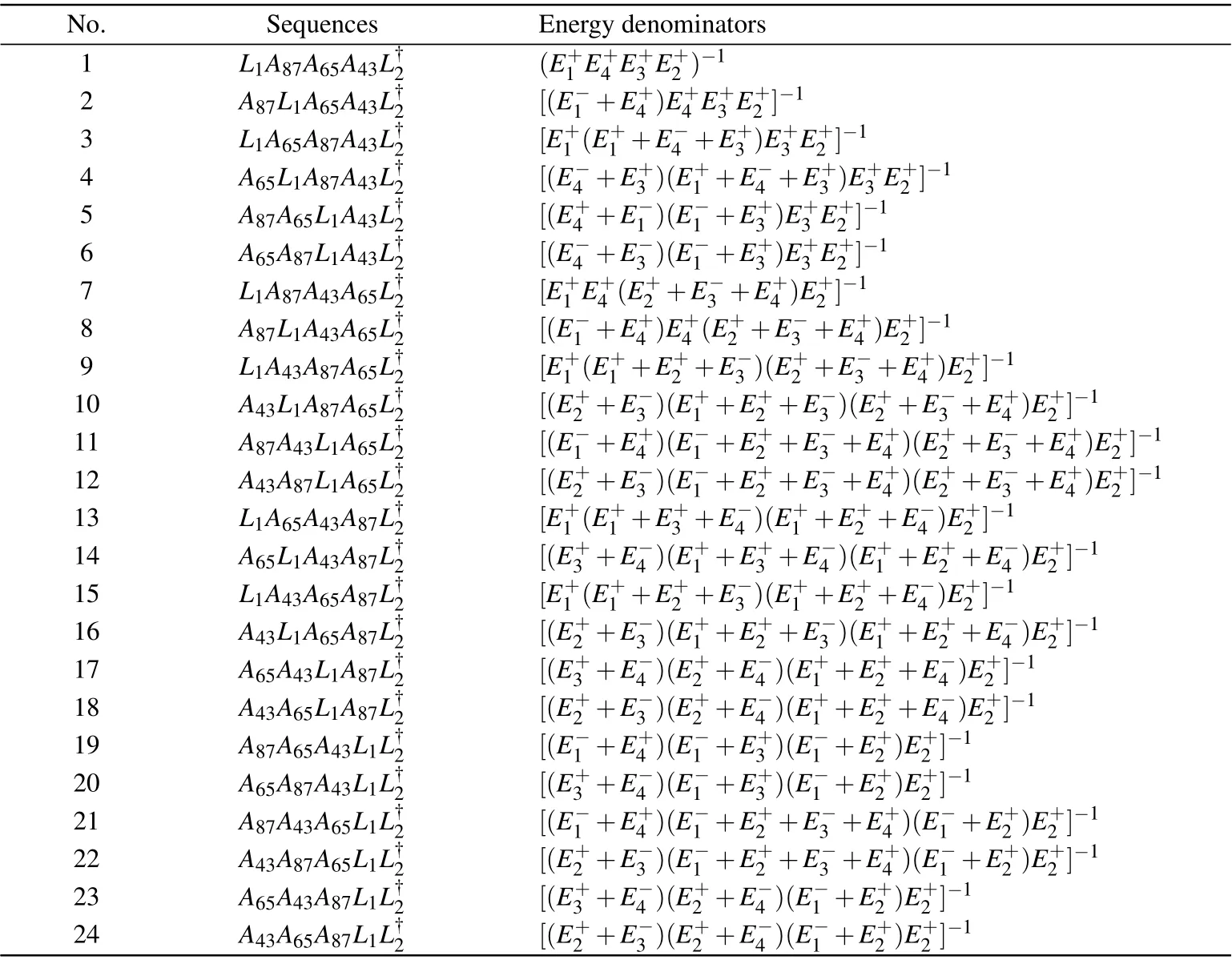
Table B2. Illustrative examples of the sequences and the associated energy denominators, for an electron transfer from the quantum dot D2 to D1 through the main loop of Majorana stabilizer as shown in Fig.1.
猜你喜欢
杂志排行

Chinese Physics B的其它文章
- Two-dimensional finite element mesh generation algorithm for electromagnetic field calculation*
- Stable water droplets on composite structures formed by embedded water into fully hydroxylated β-cristobalite silica*
- Surface active agents stabilize nanodroplets and enhance haze formation*
- Synchronization mechanism of clapping rhythms in mutual interacting individuals*
- Theoretical study of the hyperfine interaction constants,Land´e g-factors,and electric quadrupole moments for the low-lying states of the 61Niq+(q=11,12,14,and 15)ions*
- Ultrafast photoionization of ions and molecules by orthogonally polarized intense laser pulses: Effects of the time delay*