Convection effect on an arc plasma evolution process in a two parallel contact system
2020-05-06JianningYIN尹健宁ShunguiLIU刘顺贵FengTANG唐峰QishenLV吕启深andXingwenLI李兴文
Jianning YIN (尹健宁),Shungui LIU (刘顺贵),Feng TANG (唐峰),Qishen LV (吕启深) and Xingwen LI (李兴文)
1 State Key Laboratory of Electrical Insulation and Power Equipment,Xi’an Jiaotong University,Xi’an 710049,People’s Republic of China
2 Shenzhen Power Supply Co.Ltd,Shenzhen 518020,People’s Republic of China
Abstract
Keywords: air arc,circuit breaker,MHD
1.Introduction
A low voltage circuit breaker(LVCB)is a crucial component for controlling and protecting a power distribution network,and its movable contact consists of two parallel contacts for products with a higher rated current [1].The arc will be ignited between movable contacts and a static contact when the fault current appears,and the arc evolution process will directly affect the breaking capacity of the LVCB.Therefore,the study of the arc evolution process of a two parallel contact structure is crucial.
Many studies have been performed on air arc behaviors.For a magneto–hydro–dynamic (MHD) simulation of an air arc,the air plasma physical properties must be obtained first.Murphy et al[2,3]calculated the transport coefficients of air,nitrogen–air and oxygen–air plasma.They also calculated the air and different metal vapor mixture plasma properties.Ander et al [4,5] and Zhang et al [6] calculated the composition and thermodynamic properties of ablated vapors of Cu,PMMA,PA6-6,PETP,POM and PE.In addition,the modeling of the plasma–sheath boundary region and the influence of the surface structure on arc voltage were studied[7,8].A sheath with a voltage–current density characteristic was proposed to represent the near-anode and near-cathode voltage,and also,the formation process of a new arc root on a splitter plate is described by it [9].Based on the above parameters,the effects of several factors,such as different mixture plasma properties [10],the ferromagnetic material[11,12],the arc ignition position [13],the erosion of the splitter plate [14] and the moving contact motion [15–17] on the arc behavior,were studied by the MHD model.Also,the behavior of the arc root was studied in[18–20].However,the quasi-steady solution for a magnetic field was assumed in the calculation.Thus,the temporal variation of the magnetic field was neglected.The studies [21,22] calculated the eddy current in the splitter plate and electrodes.
However,all of the above studies considered single contact models and few papers have been published studying the air arc evolution process in a parallel contacts model.
In this paper,a 3D MHD simulation model of two parallel contacts is built to investigate the arc evolution process.To represent the voltage drop of the electrodes,a 0.1 mm sheath with a voltage–current density characteristic is applied.For the numerical method,in order to take the temporal variation of the magnetic field in the whole calculation domain into account,the ANSYS Emag solver is applied to calculate the time-varying electromagnetic field.The coupling between the flow field and electromagnetic field uses the coupling server MpCCI.Based on the above methods,the evolution process of the anode arc root is analyzed by the current density distribution.The convection and conduction flux densities of air plasma are calculated and their effects on arc motion are quantitatively analyzed.The shape of the arc column is analyzed.The asymmetry of the anode and cathode arc root is also studied.The arc motion process of the two parallel contact system is preliminarily revealed.The study in this paper is beneficial for understanding the arc evolution mechanism of a two parallel contact system,and provides theoretical support to optimize high performance low voltage circuit breakers.
2.Numerical model and governing equations
The arc evolution process is not only determined by the electromagnetic field,but also by the gas dynamic.The arc model presented here is based on the MHD approach,where the arc plasma is described as one fluid.The plasma characteristic justifies some assumptions for the simplification.
2.1.Hypotheses
(1) The conditions of the local thermodynamic equilibrium and the laminar flow are satisfied.
(2) Evaporation from the electrodes and wall materials is not considered.The physical properties of air plasma are the functions of temperature and pressure [2].
(3) No ferromagnetic materials in the domain are presented.
2.2.Geometry model
Figure 1(a) shows the simulation model for the fluid.This model is a simplification of the miniature circuit breaker,which includes the electrode domain and arc column region.The dimensions of the model are 8 mm × 8 mm × 30 mm in the x–y–z direction.The origin of the coordinate is on the left wall (z = 0).In order to solve the electro-magnetic field,a far-away domain is built in the model.The thickness of the electrodes is 1.5 mm,and 0.1 mm near electrode layers surround the electrodes.Figure 1(b) shows the anode geometry of two parallel contacts.The anode consists of two parallel contacts,and 12 solid contacts connect them.The dimensions of contact 1 (contact 2) are 3 mm × 1.5 mm × 23 mm,and the dimensions of the 12 solids are 8 mm × 1.5 mm × 2 mm.The dimensions of the cathode are 8 mm × 1.5 mm ×25 mm.The material of the electrodes is copper.The distance between the two electrodes is 5 mm.
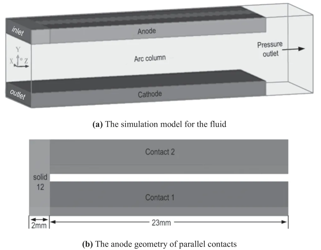
Figure 1.The geometry model.

Table 1.Equations solved in the fluid model.
2.3.Governing equations
Basically,the plasma process is modeled in detail combining the finite-element and finite-volume methods based on an MHD approach [15].A thin layer of elements with a nonlinear voltage–current density characteristic is employed to represent the voltage drop of the electrodes [13].The MHD equations are a combination of Navier–Stokes flow equations extended to include arc specific source terms with additional Maxwell equations for the electromagnetic field [13].
2.3.1.Fluid model.The Navier–Stokes flow equations are written in the form of the generalized conservation equation (1):

where Φ is the variable solved,ρ is the mass density,t is the time,is the velocity vector,ΓΦis the diffusion coefficient andSΦis the source term.All the equations solved for the fluid model are summarized in table 1 [23,24].
In table 1,
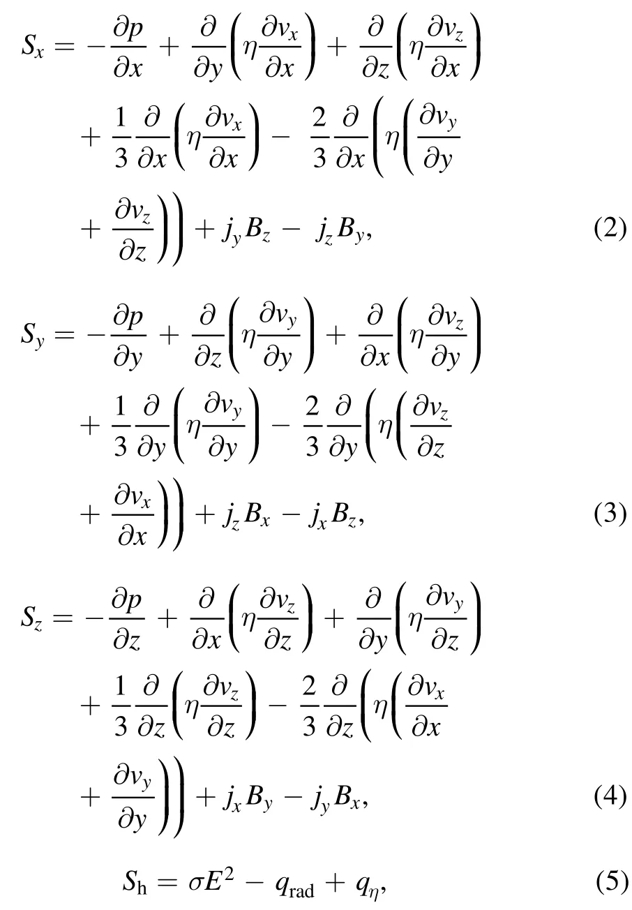
whereσE2is the Joule heat,which represents the injected energy into the air plasma.The radiation is calculated by equation (6):

whereεnis the net emission coefficient [25].
In the above equations,vx,vy,vzare the velocities of the x,y,z direction,jx,jy,jzare the current densities of the x,y,z direction,Bx,By,Bzare the magnetic flux densities of the x,y,z direction,is the Lorentz force produced by the current loop,η is the viscosity,λ is the thermal conductivity,cpis the specific heat,qηis the viscous dissipation,p is pressure,and h is enthalpy.
The Navier–Stokes flow equations are solved using the ANSYS Fluent solver [15].
2.3.2.Electromagnetic model.The motion of an arc is not only affected by the gas dynamic,but also by the magnetic field (induced by the arc itself and the current loop of the anode–arc–cathode).Therefore,the Lorentz forceis added in the source item of the momentum balance equation as shown in equations (2)–(4).
The magnetic vector potential method is adopted to solve the nonlinear transient electro-magnetic field.The equations are shown as follows [26]


where μ0is the permeability of vacuum,and σ is the electrical conductivity.The electrical conductivity of plasma is the function of the plasma temperature and pressure,φ is the electrical potential,andis the magnetic vector potential.
The electromagnetic equations (7) and (8) are solved using the ANSYS Emag solver.
During the simulation,the data transfer between the two solvers is necessary due to the interaction between the gas flow field and the electro-magnetic field.This is done by using the MpCCI [15].The electrical conductivity σ is transferred from the ANSYS Fluent to the ANSYS Emag.The Lorentz force and Joule heat are transferred from the ANSYS Emag to ANSYS Fluent by user defined codes.
The time-varying electromagnetic field induced by the current loop,including the electrodes and arc column,is calculated in this paper.Therefore,compared with most of the previous studies [5–13],the itemis included in equations (7) and (8).
2.3.3.Near-electrode model.The near-electrode voltage is an important part of the arc voltage and must be considered in the calculation.The 0.1 mm layers with a nonlinear resistance surrounding the electrodes are applied and its effective electrical conductivity is calculated by equation (9) [27]:

where J is the current density,Δyis the thickness of the near electrode layer,and Ulis the voltage drop in the near electrode layer.The value of the effective electrical conductivity is calculated by the voltage–current density characteristic [13].
A higher voltage UIhas to be exceeded at a low current density to describe the formation process of the arc root.After the formation of the new arc root,the near-electrode voltage U0is a constant.In this paper,the higher voltage UIis set to 22.3 V,and the near-electrode voltage U0is set to 10.3 V [13].
The near-electrode voltage (near-anode and near-cathode) is calculated by a nonlinear voltage–current density characteristic [13].The difference in voltage between the near-anode and near-cathode is not considered in this model.Therefore,the arc voltage may be reduced.In addition,if the difference in voltage between the near-anode and nearcathode is considered in the model,the temperature of the anode arc root will be higher.
2.4.Boundary conditions
(1) Velocity: for all walls,the velocity is set to no-slip conditions.
(2) Temperature: for the side wall (including the front surface,back surface and left surface of the arc column region,as shown in figure 1(a)) and the electrode outside planes,the environment temperature of 300 K is applied to the thermal conditions.For the pressure outlet,as shown in figure 1(a),the temperature is set to 300 K[27].At the interface between the air plasma and electrode surfaces,the temperature is determined as [13]:

(1) Pressure:for the pressure outlet,as shown in figure 1(a),the total pressure is set to 101325 Pa.
(2) Electrical and magnetic field: the electrical and magnetic field is solved in ANSYS Emag.In order to ensure the current is freely distributed between the two contacts according to the position of the arc root,the arc current is applied on the surface ‘inlet’.The electrical potential is set to zero on the surface ‘outlet’,as shown in figure 1(a) [14].For the interface between the arc region and the electrode,the boundary condition of the electrical field is described by equation (11):

For the side wall of the arc region and electrode outside planes,the boundary condition is described by equation(12):

For the boundary of the magnetic field,the zero magnetic potential is set to a far-away domain boundary to calculate the magnetic field.At the interface between the arc region and electrode,equations (13) and (14) are used [26]:

The calculating current is set tosin (ωt+π/12) A,whereω=2πf.The equations are solved with a time step of 2.5 μs,and the coupled solver of Fluent is used.To improve the initial convergence,the simulation begins with a steady state result.The position of the initial arc at z = 5 mm in this paper and this arc ignition point are determined by the distance between the arcing position and the outlet of the model according to the structure of the miniature circuit breaker.
The difference between the model established in this paper and the previous model is mainly that this model considers the two parallel contacts and their interactions.Also,the eddy current in the whole domain (arc domain and electrodes) is considered.In addition,the convection flux is calculated and its effect on the arc plasma evolution process in a two parallel contact system is analyzed in this paper.

Figure 2.Current density distribution sequences in the arc column domain.
3.Numerical results and analysis

Figure 3.Curves of current through two contacts and arc voltage.The whole process is divided into processes(1)–(6).S1–S4 represent stage (1)–stage (4).
The arc evolution process in a two parallel contact system is simulated based on a 3D MHD approach.The current density distribution,temperature distribution and the arc voltage are obtained.The arc shape from the anode to the cathode is analyzed by the current density distribution.The displacements of the arc roots are obtained.The convection flux density and heat conduction flux density are calculated at various instants.The arc evolution process and the influence of convection on it in a two parallel contacts model are analyzed.
3.1.Evolution process of an arc
The current density distribution sequences in the arc column domain are shown in figure 2.The red lines represent the position of the two parallel contacts.The current flows from the anode to the cathode.
The curves of the current through the two contacts and arc voltage are shown in figure 3.In figure 3,i is the arc current,i1and i2are the currents through arc branch 1 and arc branch 2,respectively,u is the arc voltage.The curves of the arc resistance (including total arc resistance,resistance of arc branch 1 and arc branch 2) are shown in figure 4.The resistance trend of the two arc branches is similar to the trend of the current flowing through the two arc branches.The arc motion process can be analyzed in the following stages according to the current curves,as shown in figure 3.
3.1.1.The anode arc root only appears on contact 1(t=0–0.38 ms).The starting position of the arc is at z = 5 mm.After that,the arc column moves along the electrodes due to the gas flow force and Lorentz force,so the arc voltage increases,as shown in figure 3.Also,the arc column expands.The heated air flows from arc branch 1 to arc branch 2 due to the convection effect,which results in the air under contact 2 being heated; therefore,the electrical conductivity of the air plasma under contact 2 increases.At this stage,the arc root of the anode only appears on contact 1,as shown in figure 2(a),but the convective effect provides favorable conditions for the formation of a new arc root on contact 2.After t = 0.3 ms,the current through the arc branch 2 increases.

Figure 4.Curves of arc resistance. Rarc is the total arc resistance, R1 and R2 represent the resistance of arc branch 1 and arc branch 2,respectively.
3.1.2.A new arc root is formed on contact 2(t=0.38–0.495 ms).Stage 1 (t = 0.38–0.445 ms): the electrical conductivity of the air under contact 2 is constantly increased.At t = 0.38 ms,a new arc root is formed on contact 2,as shown in figure 2(b),and the arc voltage reaches its peak.
After t = 0.38 ms,the arc column under the anode consists of two branches.The arc column under contact 1 is defined as arc branch 1 and the arc column under contact 2 is defined as arc branch 2 for the convenience of the following analysis.At t = 0.38 ms,the current density and arc column radius of arc branch 1 are larger than those of arc branch 2.The temperature gradient between the two arc branches is the largest.The air plasma of arc branch 2 is heated and the electrical conductivity is increased due to convection and conduction.Therefore,current i2increases.In contrast,current i1decreases.The resistance of the two arc branches is equal until t = 0.445 ms.
Stage 2 (t = 0.445–0.495 ms): the current flowing through arc branch 2 continues to increase due to thermal inertia after t = 0.445 ms.The arc resistance of branch 2 is less than that of arc branch 1.Therefore,the current flowing through branch 2 will continue to increase due to the decrease of arc resistance R2.When t = 0.495 ms,the current flowing through arc branch 2 reaches its local peak.
3.1.3.Current i1increases(t=0.495–0.655 ms).Stage 3(t = 0.495–0.565 ms): at t = 0.495 ms,as shown in figure 2(c),the current density and radius of arc branch 2 are larger than those of arc branch 1.After that,the electrical conductivity of arc branch 1 increases,which leads to an increase in the current through arc branch 1.The arc currents of the two branches are equal again at t = 0.565 ms.

Figure 5.Schematic diagram of the dynamic u–i curves.
Stage 4 (t = 0.565–0.655 ms): the current flowing through arc branch 1 continues to increase at this stage due to the decrease of arc resistance R1,which leads to an increase of the temperature gradient between the two arc branches.
The arc evolution processes (4) and (6) are similar to process (2),and the evolution process (5) is similar to process (3).
An alternative variation of R1and R2appears in the whole process.However,the total arc resistance always reduces in the arc evolution process according to figure 4;that is to say,the arc in a two parallel contact system always develops toward the direction in which the total arc resistance decreases.
At process (2) and process (3) of the arc evolution process,the arc voltage decreases because the cross section of the arc column becomes larger.The arc voltage increases slightly from t = 0.655 ms to t = 0.8 ms,while it decreases again at t = 0.8 ms.After t = 1.0 ms,the arc voltage increases because of the elongation of the arc column.
Figure 5 shows the dynamic voltage–current curves of the two arcs,where the curve of the black solid line represents the dynamic u–i1characteristic of arc branch 1 and the red dash line represents the u–i2characteristic of arc branch 2 [28].
In order to analyze all possible intersections of the two curves,curves (1)–(3) show the possible situations of arc branch 1.The points a–f are possible points of intersection.
Through the analysis of each intersection in figure 5,the two parallel arc branches hardly co-exist at points from‘a’–‘c’ (one of two arc branches will be extinguished).At points from‘d’–‘g’,the two parallel arc branches can co-exist.
In summary,if conditions (1) du/di1> 0 and du/di2> 0 or (2) du/di1< 0 and du/di2< 0 are satisfied,that is to say,when the arc resistance characteristics of two arc branches are consistent,two parallel arc branches can coexist.
It can be seen that the above-mentioned analysis based on the dynamic current–voltage curves could not explain the calculation results as shown in figure 3.It is predicted that the interaction between the two parallel arc branches should be considered from the view of a flow field.
3.2.Calculation results of convection and conduction
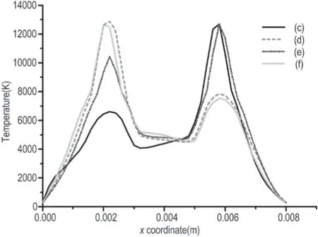
Figure 6.Temperatures on the cross section of y = 2.4 mm along the x-axis at four instants.
In order to further analyze the arc evolution mechanism in a two parallel contact system,the temperatures at the cross section of the anode arc root(y = 2.4 mm)along the x-axis at four instants (figures 2(c)–(f)) are obtained and shown in figure 6.
It can be noted that the position of arc root 1 and arc root 2 is at about x = 2.2 mm and x = 5.8 mm respectively.At t = 0.655 ms and t = 1.1 ms,the central temperature of arc root 1 is significantly higher than that of arc root 2,which leads to the direction of the temperature gradient along the positive direction of the x-axis.At t = 0.495 ms and t = 0.915 ms,the central temperature of arc root 2 is higher than that of arc root 1,which leads to the direction of the temperature gradient along the –x-axis direction.The convection and conduction are directly related to the temperature gradient.The convection and conduction will affect the movement of air plasma and the arc evolution process.
In this paper,the convective flux density is defined as[29]:

The conduction flux density is calculated by the following formula:

The distribution of the x component of the conduction flux density on cross section y = 2.4 mm at four instants(figures 2(c)–(f)) is shown in figure 8.
The arc motion process is mainly affected by convection and conduction.It can be seen that the convection flux density is much larger than the conduction flux density by comparing figures 7 and 8.That is to say,convection plays a dominant role in the arc evolution process.

Figure 7.The x component of convective flux density on cross section y = 2.4 mm ((c) = 0.495 ms,(d) = 0.655 ms,(e) = 0.915 ms,(f) = 1.1 ms).

Figure 8.The x component of conduction flux density on cross section y = 2.4 mm ((c) = 0.495 ms,(d) = 0.655 ms,(e) = 0.915 ms,(f) = 1.1 ms).
In figure 8,the curves of (c)–(f) are evaluated for the cross section at z = 9 mm,z = 11.5 mm,z = 14.5 mm and z = 17 mm,respectively (the position of the black dash line in figure 9).Figure 8 shows that the conduction flux density is zero at x = 2.2 mm and x = 5.8 mm,respectively,and the heated air plasma diffuses to both sides of the arc root.The heated air plasma diffuses to the middle of the two arc roots due to conduction,therefore,the positions of the two anode arc roots are maintained in a fixed position.
3.3.The convection effect on the arc evolution process
The flow field distribution (on the cross section of the anode arc root)at the four instants is obtained and shown in figure 9.Based on this,the effect of convection and conduction on arc evolution behavior is analyzed.
The boxes of the black dash line represent the positions of contact 1 and contact 2,as shown in figure 9(a).

Figure 9.Velocity distribution at different instants.
The vertical black dash line shows the position of the anode arc root with a larger current density.It is noted that the convective flux density in the position of the arc root equals zero at about at t = 0.495 ms,t = 0.655 ms and t = 1.1 ms,as shown in figure 7,because the velocity of the airflow is along the z-axis,while the x component of the velocity is very small,as shown in figures 9(a),(b),(d).At t = 0.915 ms,the convection flux density equals 2 × 10⁸W m-2due to the large x component of velocity in the position of the arc root,as shown in figure 9(c).
3.3.1.The evolution behavior at stage(2).The new arc root forms on contact 2 at t = 0.38 ms.The current density of arc root 1 is higher with the arc motion,resulting in the direction of convection being from arc branch 1 to branch 2.The electrical conductivity of arc branch 2 is increased and the arc resistance of arc branch 2 begins to decrease due to convection.Therefore,current i2increases.At point ‘a’,as shown in fgiure 4,i1= i2.The i2current continues to increase and i1decreases after point‘a’ due to the thermal inertia of the arc column.Until t = 0.495 ms (curve (c) as shown in fgiure 7),the convection fulx density is less than zero when z > 11.5 mm and the convection fulx density is greater than zero when z < 9 mm,which shows that the cool air behind the arc column folws to arc branch 2 and the heated air before the arc column flows to arc branch 1,as shown in fgiure 9(a).Therefore,the electrical conductivity of arc branch 1 is increased,so that current i1increases after t = 0.495 ms,as shown in figure 3.
3.3.2.The evolution process at stage(3).From 0.495 ms to 0.565 ms,the arc resistance R1decreases and R2increases,as shown in fgiure 4,due to the effect of convection.Therefore,current i1increases and i2decreases.At t = 0.565 ms,current i1= i2at point ‘b’,as shown in fgiure 3.From 0.565 ms to 0.655 ms,the arc resistance R1continues to decrease due to thermal inertia,resulting in current i1continuing to increase and i2continuing to decrease.Therefore,the temperature gradient between the two arc roots increases with the increase of the difference value of current density between the two arc branches,which leads to an enhancement of the convection effect and its direction is from arc root 1 to arc root 2.At t = 0.655 ms,the difference value of the current density between the two arc branches is the highest.The heated air before the arc column folws towards branch 2,as shown in fgiure 9(b).The electrical conductivity of branch 2 increases due to convection(curve(d)as shown in fgiure 7).Therefore,current i2increases and i1decreases after t = 0.655 ms.This explains the current change process at stage (3) during the arc evolution process.
The convection effects on the arc evolution process at stages (4) and (6) are similar to stage (2),and the convection effect on the arc evolution process at stage (5) is similar to stage (3).The arc evolution process is repetitive.
As per the above mentioned analysis,the current densities of the two arc branches under the anode do not reach the steady state in the whole arc motion process because the arc motion process is a dynamic process.Therefore,the current change process of i1and i2is a dynamic equilibrium process.
It can be seen that two arc roots appear in the anode with an increase in the current through the above analysis.The change in the current flowing through the two branches is mainly affected by the convection and arc resistance in the whole arc evolution process in the two parallel contact system according to the above analyses.However,the electrical conductivity of the arc branches will be changed due to convection.Therefore,the arc resistance of the two arc branches will be changed.In other words,the main physical mechanism of the arc evolution process is the influence of convection.

Figure 10.The displacement of the anode and cathode arc roots.
3.4.The shape of the arc column and displacements of arc roots
3.4.1.Shape of arc column.It can be noted that the size of the two arc columns varies alternately from figure 2.The new arc root forms on contact 2 after 0.38 ms.The anode has two arc roots and the cathode has one after 0.38 ms.From the anode to the cathode,the two arc branches merge into one.Therefore,the shape of the arc column is ‘Y’ type.One reason is the electromagnetic attraction of the two arc branches.The other reason is the conduction effect as shown in figure 8,which leads to the heated air plasma diffusing to the middle of the two arc roots.These two reasons also explain the phenomena of the two anode arc roots maintained in a fixed position.
3.4.2.The displacements of arc roots.The structure of the anode and cathode is different.The anode consists of two parallel contacts and the cathode consists of one contact.It will affect the displacements of the arc roots.The displacements of the arc roots will be analyzed in this section.The displacements of the anode and cathode arc roots are shown in figure 10.
The arc is ignited at z = 5 mm.Before t = 0.38 ms,the velocity of arc root 1 is faster than the cathode arc root because of the higher current density.Therefore,the displacement of anode arc root 1 is larger.At 0.38 ms,anode arc root 2 forms at z = 7.5 mm and it is behind anode arc root 1 because of the tailing of the arc.The equivalent cross section of the anode arc root increases after the formation of anode arc root 2,so that the current density of the cathode arc root is larger.Therefore,there is a slower velocity of the anode arc root than the cathode arc root.Thus,the cathode arc root will catch up with the anode arc root and the displacements of the anode and cathode arc roots are equal until 0.62 ms.The current density of the anode arc root increases more than the cathode arc root with the increase of current after 0.62 ms.Therefore,the displacement of the anode arc root is greater than the cathode arc root at 1.1 ms again,as shown in figure 10.This phenomenon can also be seen in figure 2(f).
4.Conclusions
A 3D simulation model of a two parallel contact system has been built.The anode consists of two parallel contacts in the model.A 0.1 mm near-electrode layer with nonlinear resistance is applied to simulate the formation of the arc root.The convection flux density and conduction flux density are calculated.Based on this,the arc evolution behavior of a two parallel contact system is analyzed.It can be concluded that:
(1) The arc root will extend from one contact to two contacts on parallel contacts with the arc motion.The size of two arc branches will change alternately during the arc motion process.
(2) Two anode arc roots can co-exist during the arc evolution behavior.The arc column of the two parallel contact system always develops toward the direction in which the total arc resistance decreases.The arc current change process through each arc branch is a dynamic process,and they try to reach the steady point in the arc motion process.The arc evolution behavior is affected by convection.
(3) The arc column is‘Y’type after the formation of a new arc root due to the attraction of two arc branches near the anode and heat conduction.The arc root motion is asymmetrical because of the structural asymmetry.
In future work,more attention should be paid to the plasma–sheath boundary region modelling,and the influence of the electrode motion process and splitter plates.
Acknowledgments
This work is supported by the Natural Science Foundation of Shaanxi Province of China (No.2017ZDJC-16) and Shenzhen Power Supply Co.Ltd (No.SZKJXM20170480).
猜你喜欢
杂志排行

Plasma Science and Technology的其它文章
- Study on influencing factors of ion current density measurement in corona discharge of HVDC transmission lines
- Trap distribution of polymeric materials and its effect on surface flashover in vacuum
- Improvement of the electrical resistivity of epoxy resin at elevated temperature by adding a positive temperature coefficient BaTiO3-based compound
- Controlling fine particles in flue gas from lead-zinc smelting by plasma technology
- Kinetic simulation of an electronegative plasma with a cut-off distribution and modified Bohm criterion
- Suppression of a spontaneous dust density wave by modulation of ion streaming