Study on plasma cleaning of the large-scale first mirror of the charge exchange recombination spectroscopy diagnostic on EAST
2020-04-24JiaoPENG彭姣RongYAN鄢容JunlingCHEN陈俊凌RuiDING丁锐YingyingLI李颖颖andFaliCHONG种法力
Jiao PENG (彭姣),Rong YAN (鄢容),Junling CHEN (陈俊凌),Rui DING (丁锐),Yingying LI (李颖颖) and Fali CHONG (种法力)
1 Institute of Plasma Physics,Chinese Academy of Sciences,Hefei 230031,People’s Republic of China
2 Xuzhou University of Technology,Xuzhou 221000,People’s Republic of China
Abstract
Keywords:first mirror,CXRS,EAST,plasma cleaning,cleaning uniformity
1.Introduction
All optical diagnostic systems in ITER and future magnetic confinement fusion reactors will employ in-vessel first mirrors(FMs) to view burning plasma [1].Being one of plasma facing components (PFCs) proximal to burning plasma,FMs serve in extremely harsh environments.Particularly,erosion and deposition as two main competitive effects,can modify the surface morphology of FMs,degrading their optical performance with time [2].The erosion effect caused by energetic charge exchange atoms can be mitigated significantly by means of selecting appropriate FM materials with a low sputtering yield,such as molybdenum(Mo)and rhodium(Rh)[3,4].However,deposition of materials eroded from PFCs isstill a devastating threat,greatly impairing the stability of reflective spectra [5,6].Even extremely thin transparent deposits for FMs are scarcely tolerable [7,8].
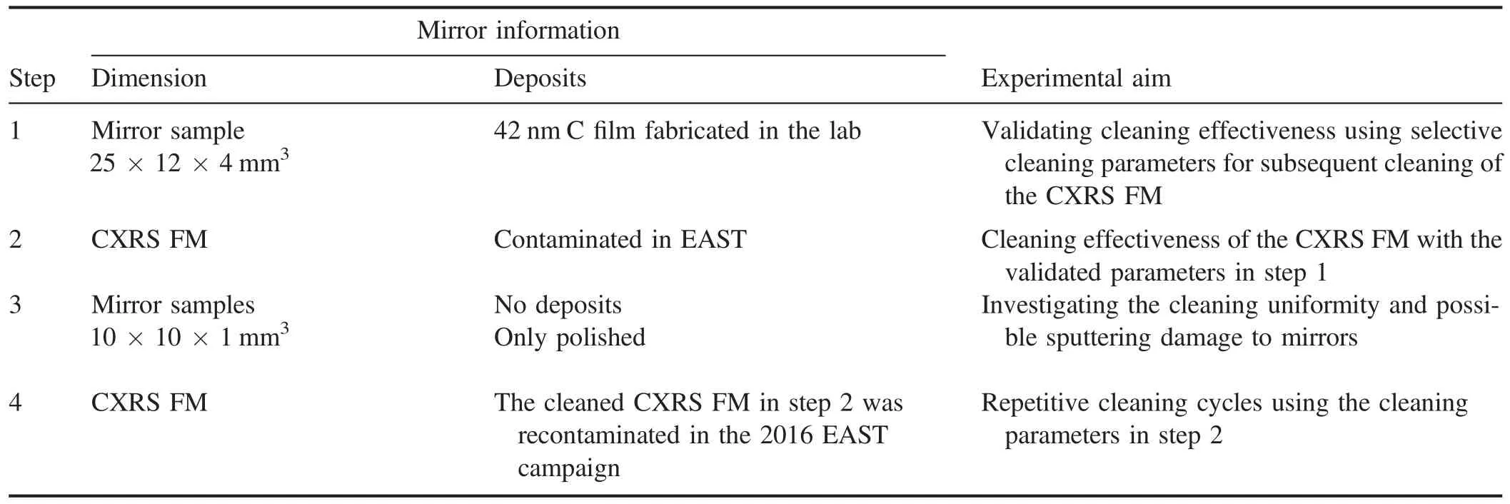
Table 1.The general experimental strategy.
The Experimental Advanced Superconducting Tokamak(EAST) has an ITER-like D-shaped cross section with different constructive PFC materials,i.e.,tungsten for the upper divertor,graphite for the lower divertor,and titanium zirconium molybdenum (TZM) alloy as the first wall [9].Various wall conditioning techniques such as glow discharge and conventional lithium evaporation have been applied to facilitate the operation of EAST.Under these circumstances,reflective mirrors of optical diagnostics in work are susceptible to contamination mainly from two procedures.First of all,wall conditioning materials (lithium (Li),silicon (Si) and boron (B)) form thick contaminant layers if the FMs are unprotected by mechanical shutters or the shutters malfunction.On the other hand,during main plasma discharges,materials eroded from PFCs will be redeposited on the surface of the FMs.The Mo cone mirrors of the POlarimeter/INTerferometer (POINT) system mounted at the inner wall without the protection of shutters,were deposited with amorphous films of 30–40 μm after the operation of experimental campaign in 2015[10].The chemical compositions of the deposits were carbon (C),Mo,Li,and oxygen (O) which were mainly from PFCs and wall conditioning materials.Additionally,the reflectivity of the charge exchange recombination spectroscopy (CXRS) diagnostic FM was dropped down to 20% of the original value at 532 nm after the operation of two experimental campaigns in 2014–2015,deteriorating the signal intensity of this diagnostic system to an unacceptably low level.Compared with the POINT system,the reflectivity recovery of the CXRS FM is more imperative taking into account the fact that the reflectivity of the CXRS FM in the operating wavelength range(400–700 nm)[11]is much more affected by the deposits than that of POINT mirrors in the operating wavelength of 432.8 μm [10].
In order to remove contaminated layers from FMs and to restore the high reflective property,effective cleaning techniques should be established.Numerous novel cleaning approaches have been proposed to clean mirror samples in the laboratory[12–23].Among these techniques,plasma cleaning is considered as the most promising method which will be applied to the in situ cleaning in ITER [24–26]due to its capability of high cleaning efficiency.With regard to the application of the plasma cleaning method to the large-scale and slightly bended CXRS FM with a dimension of 303×81×76 mm3,there are some new problems.First of all,the issue of cleaning uniformity should be addressed.There is the possibility of nonuniform interaction between large-scale plasma and deposits on the FM surface.Secondly,more attention should be paid to the possible damage of plasma sputtering to the FM surface.Considering visible thick and nonuniform deposits building up on the mirror surface,complete cleaning of local areas of the FM surface with thick deposits will definitely result in excessive sputtering of local areas with thin deposits.Ultimately,the largescale structure of the FM present greater difficulties in carrying out effective characterization before and after cleaning procedures compared with small mirror samples.
This paper presents preliminary results of cleaning the CXRS FM of EAST,including cleaning uniformity,possible cleaning damage to the FM,and new findings like redeposition during the repetitive cleaning cycles.These results are very different from some similar investigations[15,27]in the lab considering a real tokamak first mirror and large-scale mirror size.This study hopes to provide potential insights and reference into the development of the in situ cleaning of largescale FMs in EAST and possibly in ITER in the future.
2.Experimental setup
2.1.General experimental strategy
The aim of our work is to successfully remove deposits on the large-scale CXRS FM via generating stable radio frequency(RF)plasma,as well as to explore the cleaning uniformity and the effect of possible sputtering damage to the FM.In detail,our experimental strategy is shown in table 1.
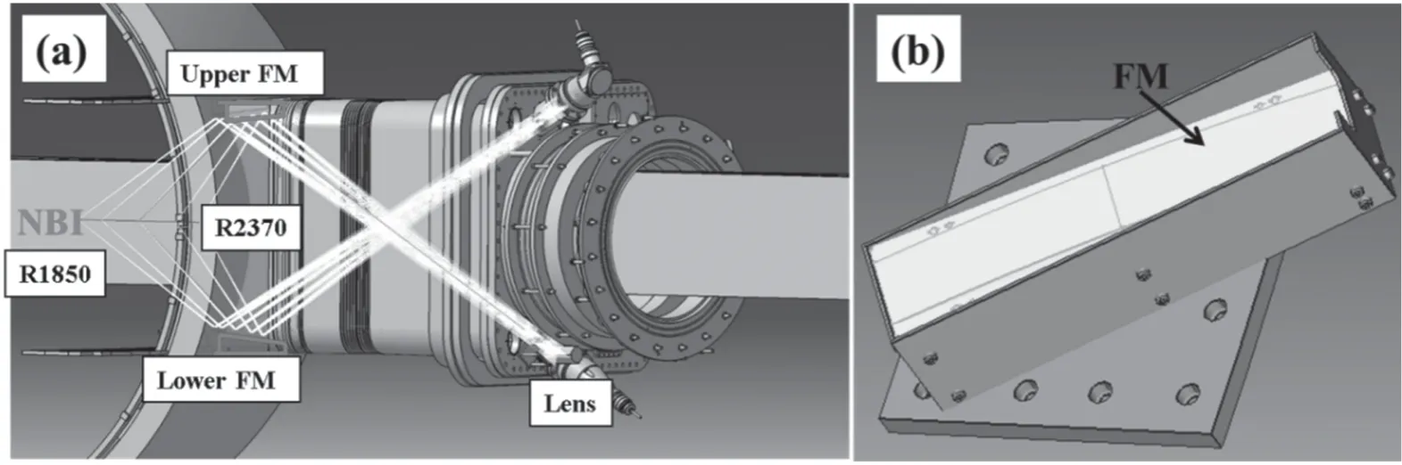
Figure 1.Schematic diagram of the CXRS diagnostic in sector A of EAST:(a) overall layout,(b) the special capsule structure of the CXRS FM.
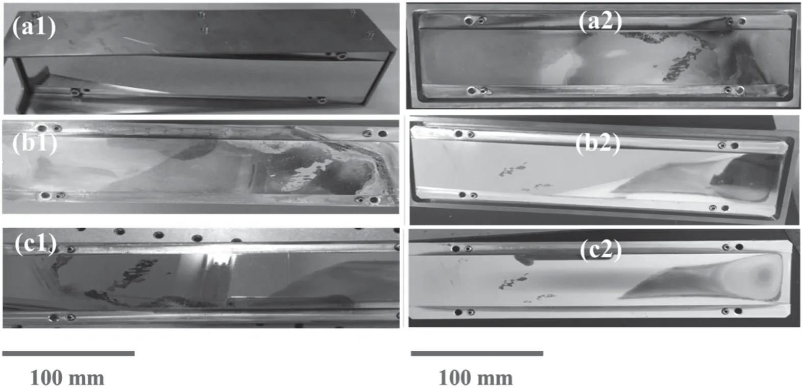
Figure 2.Photos of the(a1)pristine,(b1)exposed,and(c1)168 h cleaned mirror in the first cleaning and the(a2)exposed,(b2)81 h cleaned,and (c1) 147 h cleaned mirror in the second cleaning cycle.
2.2.Mirrors contaminated in the EAST and in the lab
The CXRS FM is the most crucial component of the CXRS diagnostic in EAST,directly determining the availability of the CXRS [11].The CXRS diagnostic is located at port A in EAST and the major radius range the CXRS diagnostic can measure is from 1850–2370 mm.Two toroidal CXRS mirrors are symmetrically placed with a distance of 970 mm and installed into TZM wall tiles with protection by mechanical shutters,as shown in figure 1(a).The upper CXRS FM is selected for study in our work.The mirror is made of 316 stainless steel (SS)with a dimension of 303×81×76 mm3as well as a small curvature of 0.008 mm–1,which can be seen in figure 1(b).A mechanical shutter remains shut during wall conditioning to protect the FM from contamination,and conversely the shutter is open for the FM to view the burning plasma during main plasma discharges.
During the 2014–2015 EAST experimental campaigns,the FM was exposed under deposition dominated conditions with total pulses of around 13 015 shots and an exposure time of about 61 364 s.The typical operation parameters were a plasma density of (2–6)×1019m−3,a plasma current of 300–600 kA,and an edge plasma temperature of 1–20 eV.Wall conditioning (siliconization,lithiation,or boronation)was periodically done prior to plasma operation.After exposure,seriously nonuniform and colorful deposits were formed on the FM surface and the presence of local flaking could be observed,which can be seen in figure 2(b1).The chemical compositions of the deposits were C,O,Mo,tungsten (W),Si,iron (Fe),chromium (Cr),nickel (Ni),and Li,which were detected by laser induced breakdown spectroscopy (LIBS) [28].Among them,Si and Li belonged to the wall conditioning elements.C,Mo,and W were from the deposition of the eroded PFC materials.O was ascribed to the oxidation in the course of measurements in air.Fe,Cr,and Ni corresponded to the main elements of the mirror itself.Definitely,the deuterium (D) element should be included in the deposits but was incapable of being detected due to the limitation of the spectrum resolution of the LIBS.
The cleaned CXRS FM was reused and recontaminated in the 2016 EAST experimental campaign for 4 months.The total exposure time was about 34 390 s under the exposure of 5072 shots.The plasma density was about(2–6)×1019m–3.The plasma current was 240–680 kA.
As described above,the main element of deposits on the CXRS mirror in EAST is C from the deposition of the materials eroded from the graphite lower divertor.To provide a reference for subsequent cleaning of the CXRS FM,an amorphous C film was fabricated on a polished mirror sample substrate with a dimension of 25×12×4 mm3in a typical RF magnetron sputtering setup in the laboratory,which is described in step 1 of table 1.The surface of the mirror sample was covered by a uniform yellow dielectric film with a thickness of about 42 nm.Detailed information on fabricating C film can be found in [29,30].
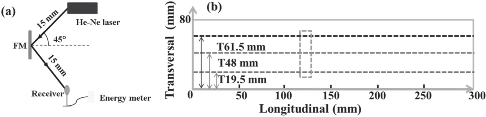
Figure 3.Schematic diagram of(a)a laser system to measure specular reflectivity and(b)the measured locations and distribution along the longitudinal(L)and transversal(T)direction of the CXRS FM surface;the green-dashed border marked in(b)is the analysis area for SEM,EDS,and LIBS.
2.3.Plasma cleaning of the mirrors
All the mirrors mentioned in table 1 were cleaned under the same cleaning regime and cleaning parameters in the laboratory.In the cleaning regime of RF capacitive coupled plasma in the laboratory,all the mirrors served as a powered electrode and the RF power feed was connected directly to the backside of the FM,which was very similar to the cleaning system in [31]specified for ITER.The mirrors employed in all the cleaning experiments were not actively water cooled.A grounded shield with a gap distance of 4 mm to the CXRS FM was used to avoid discharge ignition at the backside of the mirror.After applying an RF electric field with a frequency of 13.56 MHz to the mirror,a direct current negative bias (namely self-bias) was formed.The self-bias was the most important parameter to control ions’ energies.After being accelerated by the self-bias,ions sputtered the deposits and ultimately removed deposits completely from the mirror surface.
The self-bias and cleaning time were desirable to exactly remove deposits and simultaneously avoid the possible mirror damage.A double Langmuir probe was placed at a distance of 20 mm away from the middle of FM to measure local plasma parameters.A high speed phantom V711 charge-coupled device (CCD) camera was used for monitoring plasma distribution.
2.4.Characterization of the morphology and optical properties of FMs
All the mirrors were characterized before and after the cleaning procedures.Three types of mirrors were used in dedicated experiments with different purposes as described in table 1,and different measuring methods were used for the corresponding mirrors.
2.4.1.The SS sample coated with C films in the laboratory.The thickness of the C film was acquired by an ellipsometer(J.A.Woollam Co.Inc.M-2000U)[30].The total reflectivity and diffuse reflectivity in a wavelength range of 250–1500 nm were monitored by an UV–vis-NIR UV 3600-MPC 3100 spectrophotometer.
2.4.2.The CXRS FM and the mirror samples with a dimension of 10×10×1 mm3.A LIBS technique was employed to confirm the chemical compositions of deposits on the CXRS FM.The basic schematic diagram and measurement mechanism are provided in [32].The average surface roughness of the mirrors was measured by a S Neox 3D optical profiler.An area of 850×709 μm2in the middle of the mirror sample was chosen for measurements.Due to incompatibility with such a large-scale measuring surface of the CXRS FM mirror for a spectrophotometer,a laser measurement system was specifically built to detect the reflectivity of the CXRS FM and the mirror samples with dimensions of 10×10×1 mm3,as presented in figure 3.The specular reflectivity of the mirror samples and the CXRS FM were measured using a continuous He-Ne laser at 532 nm which was included in the operating wavelength range of the CXRS diagnostic.The angle of the incident light with the mirror surface was 45°.The ratio of energy of the reflected light by the mirror surface to the energy of the source light from the laser is defined as the specular reflectivity.Considering the measured specular reflectively is not an absolute value,a conception of a relative reflectivity was used in the paper.The relative reflectivity means the ratio of the reflectivity of a measured point to the reflectivity of the pristine polished mirror.To obtain the distribution of the specular reflectivity on the mirror surface,many points distributing uniformly along the mirror surface were measured,as shown in figure 3(b).A TESCAN VEGA 3 scanning electron microscopy (SEM) and energy dispersion spectroscopy (EDS) were used for the analysis of the surface morphology and chemical composition of the CXRS FM.Figure 3(b) marks the analyzed area.
3.Results and discussion
3.1.Cleaning of the C-coated SS mirror sample
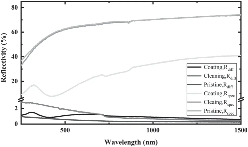
Figure 4.The specular (Rspec) and diffuse (Rd) reflectivity of the pristine,coated,and cleaned mirror.
The desirable cleaning parameters to remove the deposits from the CXRS FM should simultaneously satisfy the requirements of cleaning effectiveness and avoiding cleaning damage to the FM to the greatest possible extent.Considering the cleaning damage of the FM will probably cause the distortion of light signals,an attempt to acquire a relatively low cleaning speed is made firstly even though the cleaning efficiency has to compromise for the subsequent reuse of the cleaned mirror in tokamaks.Before cleaning,a series of cleaning tests were performed to find appropriate parameters.The self-bias,gas pressure,and RF power were adjusted to explore their effects on the cleaning results.Argon (Ar) gas pressure was firstly set as 0.5 Pa,and then the self-bias,the most important parameter,was gradually increased from–100 V to–200 V at an increment of –20 V via augmenting the RF power from 10–40 W.The selection of the starting self-bias of –100 eV was because the corresponding accelerated ion energy was about 100 eV,approximate to the sputtering threshold of Ar to C.As a result,the cleaning with a self-bias of higher than –200 V was not pronounced,which was probably ascribed to too low ion fluence or ion energy.When the self-bias was–200 V,the deposits on the mirror sample were successfully removed within a duration of 12 h.Therefore,it can be supposed that the cleaning parameters (0.5 Pa,–200 V) were relatively appropriate to be used to remove deposits.The cleaning time was determined by observing the remaining deposits on the FM surface with naked eyes from a viewing window of the cleaning setup.When it was observed that most of the deposits on the mirror surface were removed,the cleaning switched off instantly to avoid presumable damage caused by excessive cleaning.The coated mirrors in the laboratory were completely cleaned with a gas pressure of 0.5 Pa,a self-bias of –200 V,and a duration time of 12 h after further confirmation of the reflectivity.The plasma density and temperature were about 7×10¹⁴m–3and 2 eV,respectively.
The changes of the specular (upper) and diffuse (lower)reflectivity of the pristine,coated,and cleaned mirror are given in figure 4.It can be seen that the specular reflectivity is successfully recovered,and simultaneously the obtained diffuse reflectivity is below 3%.At 532 nm,the specular reflectivity of the cleaned mirror (63.23%) is about 99% of the initial value (63.96%) and the increase of the diffuse reflectivity is significantly slight,from 1.1%–1.7%.The complete removal of the C film demonstrates that the cleaning rate is around 3.5 nm h−1.These cleaning parameters are validated by the sufficiently effective removal of the C deposits and subsequently will be applied to the cleaning of the CXRS FM.
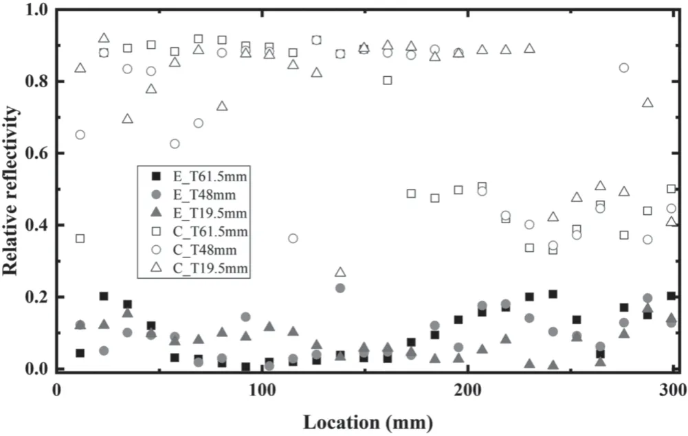
Figure 5.The relative specular reflectivity at 532 nm of the exposed(E_,solid marks) and cleaned (C_,hollow marks) large mirror at different locations along the FM surface in the first cleaning;in this figure,E_T61.5 mm,E_T48 mm,and E_T19.5 mm mean the reflectivity of the exposed CXRS FM at the locations of 61.6,48,and 19.5 mm along the transversal direction before cleaning;C_T61.5 mm,C_T48 mm,and C_T19.5 mm mean the reflectivity of the cleaned CXRS FM at the locations of 61.6,48,and 19.5 mm along the transversal direction after cleaning.
3.2.Cleaning of the CXRS FM
When the CXRS FM underwent cleaning treatment,all the cleaning parameters were kept the same as those in section 3.1.The Ar pressure was 0.5 Pa,resulting in a selfbias of –200 V with an RF power of 40 W.The electron density and electron temperature of the plasma were about 7×10¹⁴m–3and 2 eV,respectively.The resulting ion flux can be calculated roughly as 2×10¹⁶m–2s–1.When the plasma cleaning treatment lasted for 168 h,most deposits on the FM were removed as could be seen by visual inspection through the viewing window.Considering possible damage to the CXRS FM and the resulting distortion of the relative diagnostic signal,the cleaning was stopped.
Residuals are visible in some areas,as figure 2(c1)shows.From the evolution of the reflectivity which is presented in figure 5,the reflectivity of the entire exposed FM is degraded dramatically below 20% of the pristine value at 532 nm due to seriously visible nonuniform deposits on the FM surface.Nonuniform cleaning on the large mirror is observed.The relative reflectivity varies significantly from 30%–92%.The reflectivity at the locations less than L210(location 210 mm along the longitudinal direction) is much higher than that at the locations larger than L210.Namely,the reflectivity shows strong dependence on positions along the surface,of whose reasons are required to be explored further.
3.3.Cleaning uniformity and sputtering damage
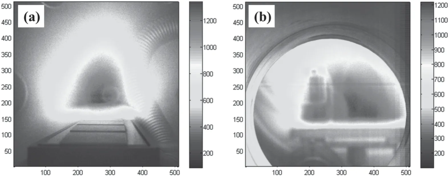
Figure 6.The plasma distribution along the (a) transversal and (b) longitudinal direction of the CXRS FM.
As for the large-scale plasma generated for the cleaning,there is a possibility of the presence of nonuniform distribution.The plasma distribution was monitored by means of a CCD camera,as shown in figure 6.Figure 6 shows the plasma emission along the transversal direction (figure 6(a)) as well as the longitudinal direction (figure 6(b)) of the FM.The intensity of plasma emission can qualitatively demonstrate the corresponding plasma distribution.The color bar on the right side of the pictures shows the relative light intensity of every pixel.The quantitative relationship of the color and light intensity is not determined.As shown in figure 5,the general plasma distribution is symmetrical in the entire vacuum chamber.At the transversal and longitudinal directions,the plasma shows a similar distribution,more intensive for central plasma than the edge plasma.One can note that the part of plasma proximal to the FM surface is basically uniform,making a main contribution to the cleaning effect.It can be assumed that the part of the plasma affecting cleaning results is uniform.
With the aim to further understand the role of the plasma distribution in cleaning uniformity,dedicated cleaning tests were made by sputtering polished mirror samples with a dimension of 10×10×1 mm3.The selection of polished mirrors with no coatings is to control the unique variable.That is,the factor of deposits is purposefully excluded and the single effect of the plasma distribution is expected to be explored.The dedicated cleaning experiment is undertaken not only to understand the cleaning uniformity,but also to assess possible cleaning damage by means of monitoring the surface roughness (Sa) and reflectivity at different locations along the FM surface.The SS mirror samples were inserted into different locations of the CXRS FM-like sample with the same size and material as the real CXRS FM,which can be seen in figure 7(a).
The polished mirror insets with the same material as the CXRS FM were sputtered with different times for 1,5,25,and 100 h,respectively.These insets were put into the same locations as the measurement areas of the reflectivity in figure 3 along the transversal direction.The Sa of the sputtered insets is shown in figure 7(b).It can be seen that the Sa of insets at the same location gradually grows with increasing sputtering time.1 h sputtering causes no any change in Sa compared with the pristine polished mirror.The sputtering time of 5 h causes a slight increase of Sa from 14–18 nm.A relative large rise of Sa can be noted when the sputtering time increases to 25 and 100 h.However,the difference in Sa in the cases of 25 and 100 h is not pronounced.It appears that no obvious dependence of Sa changes on locations under the same sputtering time.
The change in the measured specular reflectivity of the insets with positions and cleaning times is shown in figure 7(b).Regardless of different locations and different times,the reflectivity of these insets is very approximate.The maximum loss of the relative reflectivity is merely 4% compared with the virgin value.The difference between the highest and lowest reflectivity for the sputtered mirrors is only 2.8%,which is negligible.It can therefore be supposed that despite sputtering with a duration of 100 h,the specular reflectivity is not affected pronouncedly and shows no obvious dependence on the locations along the mirror surface.As can be seen from the roughness and specular reflectivity,the 100 h of sputtering leads to the enhancement of Sa to 28 nm,posing a roughening to mirror surface to a certain degree.Nevertheless,the specular reflectivity does not change correspondingly,indicating that the 100 h of sputtering does not change the morphology significantly and the resulting damage to the mirror surface is tolerable.
As described above,it can be supposed that the plasma distribution exerted an insignificant effect on the cleaning uniformity,in accordance with the basically uniform plasma distribution on the FM surface.Furthermore,the damage from excessive sputtering less than 100 h to the mirror surface is negligible for the change of the specular reflectivity.On a basis of the above experimental results,the lower CXRS FM achieved almost complete recovery of the reflectivity via additional cleaning of 109 h from 78.3–187.3 h under identical cleaning parameters to those of the upper CXRS FM of this study [28].
3.4.Repetitive cleaning of the CXRS FM contaminated in the 2016 experiment
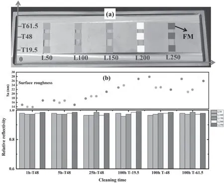
Figure 7.(a)The insets at different positions of the CXRS FM-like sample,(b)the relative reflectivity(column)and roughness(solid round points at the top of columns) of the small SS samples with the different locations and different cleaning times.
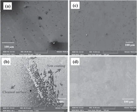
Figure 8.SEM patterns of (a) exposed,(b) transitional region of the new film and cleaned area,(c) formation of the new carbon film,and(d) completely cleaned area.
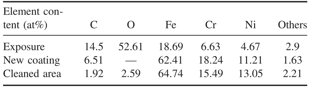
Table 2.Element content of the CXRS FM in the second cleaning cycle.
The cleaned CXRS FM was reused in the 2016 EAST campaign and was contaminated again during exposure as can be seen in figure 2(a2).Significantly nonuniform deposits were clearly visible on the surface.The SEM pattern in figure 8(a)shows compact contaminated layers on the FM surface and the main elements of the deposits are C and O indicated by the EDS results in table 2.The measured results of the LIBS demonstrated the presence of Li.These results are very similar to that from the [28].The right part of the FM has thicker deposits than that of the left,which is similar to the first exposure in section 3.2.Correspondingly,the relative reflectivity shows dependence on the locations of the surface,varying 60%at the left to lower than 20%at the right,and can be seen in figure 9.Plasma cleaning was applied to the FM with a duration of 81 h and a photo of the cleaned mirror is shown in figure 2(b2).In general,the reflectivity of the entire CXRS FM rises and most deposits are removed.More attention should be paid to the difference in cleaning results for the different locations along the mirror surface being very pronounced.As for the areas less than L200,the relative reflectivity at edge areas (T19.5 and T61.5) reaches approximately 90%,corresponding to a relatively shiny and smooth cleaned mirror surface.However,for the locations from L200–L300,the reflectivity is lower,about 70%due to a small quantity of residuals.It can be noted that on account of much more residuals,the reflectivity for the area of T48 gradually decreases and even reaches a very low level of 40%at the locations of L150–L200.
Taking into account the results of the sputtering uniformity tests mentioned in section 3.3,even a duration of 100 h of sputtering does not exert a pronounced modification in terms of reflectivity and morphology,and the cleaning treatment continued to 147 h.After longer cleaning of the residuals,it is observed that the areas of T19.5 and T61.5 have been almost completely cleaned.As presented in table 2,the content of C and O,as the main elements of the contaminant layer on the FM surface,sharply decreases,also indicating the complete cleaning for the both areas.The reflectivity of all corresponding locations is higher compared with 81 h,reaching up to 90%.Note that for the locations from L0–L200,regardless of an additional 66 h of cleaning,the reflectivity remains almost unchanged,in accordance with the results in section 3.2.Whereas for the area of T48,the reflectivity obtained at different locations exhibits a significant difference from the edge areas of T19.5 and T61.5.At locations less than L70,despite the additional 66 h of sputtering,the reflectivity can be maintained excellently,similar to T19.5 and T61.5.Unexpectedly,at locations from L70–L250,the relative reflectivity after 147 h of cleaning is surprisingly lower than that of 81 h of cleaning.In the location range of L130–L250,the reflectivity of 147 h of cleaning is even lower than that of the exposed mirror.From figure 2(c2),it should be noted that for the locations of L70–L130,a new light yellow film is formed on the surface in comparison with figure 2(b2),leading to a drop in the relative reflectivity.From L130–L250,the formation of a thicker film indicated by the dark yellow color in figure 2(a2),consequently deteriorates the reflectivity which is even lower than that of the mirror after exposure.The higher reflectivity than that of 81 h of cleaning in the range of L250–L300 demonstrates the removal of more deposits.These new films are probably from the redeposition of sputtered large numbers of residuals,taking into account that the main element of the new films is C which is confirmed by EDS in table 2.The evolution of the reflectivity can reflect and account for the redeposition process of sputtered deposits at the area of T48 during the cleaning process after 81 h of cleaning.First of all,the completely cleaned area suffers from overcleaning,but with no significant damage to the mirror surface,as can seen in figure 8(d).Simultaneously,for the areas with thick residuals,the deposits are sputtered and redeposited instantly in the vicinity,forming a new film on the completely cleaned mirror surface,as can be seen in figure 8(c),producing a new visible transitional region between the new coating and the completely cleaned area,as can be seen in figure 8(b).The closer the distance to the residuals,the thicker the redeposition builds up and the lower the resulting relative reflectivity is.This can give a relatively reasonable explanation for higher reflectivity at the locations of L70–L130 than that at locations of L130–L250.Little attention is paid to the redeposition in the process of cleaning small mirror samples in previous investigations.The redeposition during cleaning is mainly due to the areas with the thick deposits on the mirror surface.
It should be noted that the almost complete recovery of the reflectivity for the lower CXRS FM in[28]differed a lot from the partial recovery of the reflectivity for the upper one in this study.Furthermore,no redeposition was observed for the lower CXRS FM in [28].The difference in cleaning results for the two CXRS FMs is mainly ascribed to the distribution and thickness of deposits along the CXRS FM surface.Compared with the lower CXRS FM in [28],the deposits on the upper CXRS FM of this study shown in figures 2(a2) and (b1) are more nonuniform and thicker,which can be indicated by the evolution of the reflectivity.
4.Conclusions
An experimental investigation into applying RF plasma cleaning to the CXRS FM of EAST has been performed to remove the deposits from the FM,consequently recovering its high reflectivity.The reflectivity of the CXRS FM is dramatically degraded due to seriously nonuniform contaminant layers deposited on the CXRS FM surface.After cleaning for 168 h with the validated cleaning parameters in the lab,it was found that the reflectivity was recovered up to 92% of the original value at 532 nm,making the cleaned mirror eligible to be reused in the next EAST campaign.However,the reflectivity shows a strong dependence on locations along the surface,presumably correlated to the deposits distribution or plasma distribution on the mirror surface.
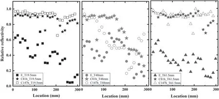
Figure 9.The relative specular reflectivity at 532 nm of the exposed (E_,solid marks),cleaned for 81 h (C81h_,solid star marks),and cleaned for 147 h (C147h_,hollow marks) large mirror at different positions along the FM surface in the second cleaning;in the figure,E_T61.5 mm,E_T48 mm,and E_T19.5 mm mean the reflectivity of the exposed CXRS FM at the locations of 61.6,48,and 19.5 mm at the transversal direction before cleaning;C81h_T61.5 mm,C81h_T48 mm,and C81h_T19.5 mm mean the reflectivity of the cleaned CXRS FM at the locations of 61.6,48,and 19.5 mm at the transversal direction after cleaning for 81 h;C147h_T61.5 mm,C147h_T48 mm,and C147h_T19.5 mm mean the reflectivity of the cleaned CXRS FM at the locations of 61.6,48,and 19.5 mm at the transversal direction after cleaning for 147 h.
A dedicated experiment of cleaning polished mirror insets into a CXRS FM-like sample was made to explore the influence of plasma distribution on cleaning uniformity.The plasma generated on the mirror surface could be considered uniform.The surface roughness(Sa)of the insets at the same position gradually increases with the increasing sputtering time.It seems that there is no obvious dependence of the evolution of Sa on locations under the same sputtering time.The 100 h of sputtering leads to the enhancement of Sa to 28 nm,resulting in the roughening of the mirror surface to a certain degree.However,the specular reflectivity does not change correspondingly.The reflectivity remains almost unchanged,regardless of different positions and different sputtering times.Therefore,it can be supposed that the damage caused by excessive sputtering less than 100 h to the mirror surface is negligible in terms of the change in the reflectivity.The cleaned CXRS FM was reused in the 2016 EAST campaign and was recontaminated during exposure.After 147 h of repetitive cleaning to remove the deposits of the reexposed CXRS FM,redeposition was observed,resulting in the incomplete recovery of the reflectivity.
We hope that the results obtained in our work provide potential insights into the development of in situ cleaning of FMs in EAST and possibly in ITER.Future in situ cleaning should be started when contaminant layers on the FMs’ surface are very thin to avoid a very long period of cleaning and presumable redeposition due to thick and nonuniform deposits.
Acknowledgments
This work is subsidized by National Natural Science Foundation of China (Nos.11975269,11905252,11675218,11675219,11775260,11861131010,11875230) and the National Key R&D Program of China(Nos.2017YFA0402500 and 2017YFE0301300).The authors would like to thank B.G.Wang,H.Xie,and X.H.Yin for their help during measurements and analysis of some of the experimental data.
ORCID iDs
杂志排行
Plasma Science and Technology的其它文章
- Three dimensional nonlinear shock waves in inhomogeneous plasmas with different size dust grains and external magnetized field
- Study of ionic wind based on dielectric barrier discharge of carbon fiber spiral electrode
- Theoretical research on the transport and ionization rate coefficients in glow discharge dusty plasma
- Decomposition of dioxin-like components in a DBD reactor combined with Hg/Ar electrodeless ultraviolet
- Measurements of plasma parameters in a hollow electrode AC glow discharge in helium
- Investigation of the self-induced magnetic field characteristics in a pulsed plasma thruster with flared electrodes