Optimization Method of Bearing Support Positions in a High-Speed Flexible Rotor System
2020-02-01TANGChangkeJIANGYanhongLIUJing刘静
TANGChangke,JIANGYanhong,LIUJing(刘静)
1 College of Mechanical Engineering, Chongqing University, Chongqing 400044, China 2 High-Speed Railway Bearing Co., Ltd., Zhejiang 324000, China 3 School of Marine Science and Technology, Northwestern Polytechnical University, Xi’an 710072, China
Abstract: Bearing support position is one of main factors affecting vibration characteristics of rotor systems. To optimize the bearing support positions in a high-speed flexible rotor system (HSFRS) based on the vibration characteristics, an optimization method of bearing support positions in the HSFRS is proposed. In this method, a finite element (FE) model of a high-speed flexible rotor (HSFR) was established. The natural frequencies and mode shapes of the HSFRS were used to obtain the initial design scheme of the bearing support positions. A frequency characteristic equation of the HSFRS was established to obtain the critical speeds of the HSFRS. And a dynamic model of the HSFRS was established to analyze the vibration characteristics for different bearing support position cases. The problem of optimizing bearing support positions in the HSFRS was solved by the developed method. The results showed that vibration amplitudes of the HSFRS were more stable when the bearing support positions were optimized. This study can provide a new method for optimizing bearing support positions of rotor systems.
Key words: flexible rotor system; optimal design; vibration characteristic; bearing support position
Introduction
Rotor systems widely exist in various fields of rotating machinery, such as turbines, compressors, turbojet engines and so on. The bearing support position is one of main factors affecting vibration characteristics of rotor systems. Thus, an optimization method of bearing support positions in rotor systems should be developed.
Numerous researches focused on the design and optimization methods of supporting stiffness, critical speed, vibrations, and dimension parameters. Pugachevetal.[1]treated the critical speed as the constraint condition and used the traditional optimization algorithm to optimize the vibration responses of a rotor system. Huangetal.[2]used different optimization algorithms to optimize the critical speed of a rotor system and discovered that the multi-objective genetic algorithm had a better effect. Wangetal.[3]developed the critical speed distribution as the objective function to optimize a rotor system by using the evolutionary algorithm. Jiaoetal.[4]developed a numerical method to obtain the responses of gain with the oil film damper bearing and optimized the bearing stiffness. Wuetal.[5]studied the discreteness laws between the support stiffness and critical speed. Chen[6]established a coupling dynamic model of rotor-bearing systems to study the vibration, critical speed, and sensitivity of unbalance response. Ou and Li[7]combined the modal analysis and finite element (FE) method to analyze vibration characteristics of an engine rotor-support-casing system. Hongetal.[8]proposed a FE model to calculate the dynamic responses of a rotor and analyzed the influence of bearing stiffness. Chiangetal.[9]studied the vibration responses of single and double rotor-rolling bearing system based on the FE method. Liuetal.[10-13]proposed different dynamic models considering the bearing deformation and defects. Sun[14]proposed a FE model of two-rotor gas turbine engine and calculated the sudden unbalanced response caused by blade loss. Hu and Palazzolo[15]established a FE model considering the gyroscopic and bearing stiffness to study the modal characteristics of a flexible rotor system (FRS). Jinetal.[16]studied the bearing varying compliance on the nonlinear dynamic of a rotor system by a proposed analytical model. Heidari and Safarpour[17]developedH∞andH2methods to obtain the optimal bearing stiffness and damping ratio of a FRS. Lietal.[18]proposed a general vibration model to analyze the vibrations of a FRS. Zhengetal.[19]presented a FE model to study the effects of the bearing stiffness and material properties of rotor on the double frequency vibrations of a FRS. Ghafarietal.[20]conducted a dynamic model to analyze the bifurcation of a rotor system. Metseboetal.[21]provided a mathematic simulation method to study the vibrations of a flexible rotor (FR).
As the above listed descriptions, most previous works only focused on the optimization methods of rotor systems based on the evolutionary algorithm, few works were focused on the optimization methods of high-speed flexible rotor systems (HSFRSs) by optimizing the natural frequencies and mode shapes. However, the effects of bearing support positions were ignored in the above listed literature. Therefore, it is a new research direction to optimize the design of rotor systems by optimizing the bearing positions.
1 Optimization Method of Bearing Support Positions in HSFRSs
1.1 FE model of a high-speed flexible rotor (HSFR)
According to the FE theory, a FE model of a HSFR is established. The natural frequencies and mode shapes of a HSFR are obtained by the free modal analysis. According to the mode shapes, the points with the relatively small amplitude of a HSFR are marked as the possible nodes. The mode shapes of a HSFR are shown in Fig. 1. The first three mode shapes of rotor are obtained by using modal analysis method of FE model. In each mode shape, the amplitudes of pointsA,B,C,D, andEare smaller than those of other positions, so pointsA,B,C,D, andEare selected as possible nodes.

Fig. 1 Mode shapes of a HSFR
1.2 Frequency characteristic equation for HSFRS
When the gyro torque is considered, the shaft will be bent due to the unbalanced mass excitation. Both the orbit and rotary motions of the rotor are formulated at the same time, where line 1 is the axis of orbit motion and line 2 is the axis of rotary motion as shown in Fig. 2. In Fig. 2,ωFandωBare the orbit motion speeds in the forward and backward whirling directions, respectively; andΩis the rotational speed of rotor. When the directions ofωFandΩare the same, it is the forward whirling motion. When the directions ofωBandΩare different, it is the backward whirling motion.

Fig. 2 Forward and backward whirling motions of FRSs: (a) forward whirling motion; (b) backward whirling motion
When the rotational speed isΩ, the frequency characteristic equation for HSFRSs is formulated as
|-M1ω2+J1Ωω+K1|=0,
(1)
whereM1,J1, andK1are the assembled mass, gyroscopic matrix and stiffness matrix of FRSs, respectively, andωis the whirling angular velocity. By solving Eq. (1), the frequencies for forward and backward whirling motions can be obtained. These frequencies can reflect the variation of angular velocities of whirling motions during the changing processing ofΩ. IfΩ= ±ωis substituted into Eq. (1), the critical speeds and natural frequencies for forward and backward whirling motions can be solved, respectively.
According to the requirements of rotor design, the possible nodes are combined and substituted into Eq. (1), and the critical speeds under different node combinations are calculated. According to the requirement of working speeds of rotor system, the node combinations are selected as appropriate node combinations, and their critical speeds are not close to the working speeds.
1.3 Dynamic model of HSFRSs
According to the FE method[22], the equations of motion for HSFRSs are given by
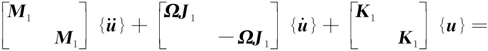
(2)
Fb=KTδn,
(3)
whereKTis the contact stiffness;δis the contact deformation of bearing rollers; the ball and roller bearing load-deformation exponentsnare 3/2 and 10/9, respectively.
According to the selected appropriate node combinations, add the contact stiffness of bearings to the corresponding nodes and substitute into Eq. (2). The vibration characteristics of HSFRSs under different node combinations are calculated and studied. When the root-mean-square (RMS) values of displacement, velocity and acceleration are smaller, it represents that the vibration characteristics are more stable.
1.4 An optimization method of bearing support positions in HSFRSs
According to the dynamic analysis method, the dynamic characteristics of HSFRSs under different node combinations are analyzed, and the time-domain vibration curves of HSFRSs under different node combinations are obtained. The time-domain vibration curves with a smaller amplitude and more stable vibration is selected, and the corresponding node combination is the optimal bearing support position. The flow chart of optimization method of bearing support positions in HSFRSs is shown in Fig. 3.
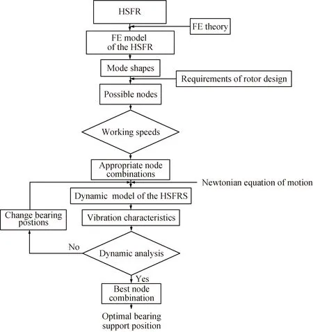
Fig. 3 Optimization method of bearing support positions in HSFRSs
2 Numerical Analysis
The schematic diagram of a HSFR is shown in Fig. 4. To solve the problem of bearing support position design of a HSFR, the optimal bearing support positions of HSFRSs are determined by the optimization method of bearing support positions in the HSFRS.
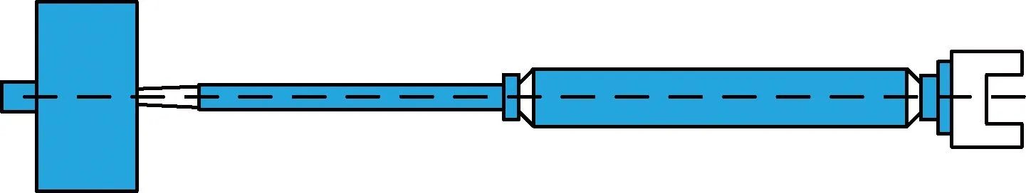
Fig. 4 Schematic diagram of a HSFR
2.1 FE model validation
The FE model and experimental method of modal analysis are shown in Figs. 5(a) and (b). The first seven natural frequencies are obtained. These natural frequencies are compared with the experiment values, as shown in Table 1. The maximum error between the simulation values and experiment values are less than 5%. The simulation values are basically consistent with the experiment values. Therefore, the FE model is effective.

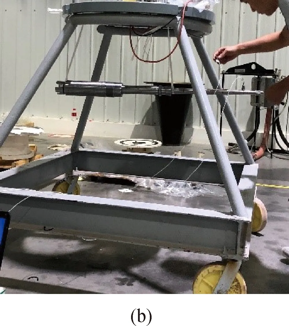
Fig. 5 Two modal analysis methods: (a) FE method and (b) experimental method Table 1 First seven natural frequencies from simulation and experiment
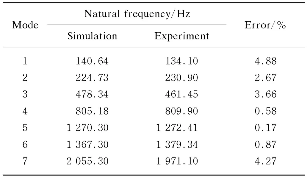
Mode Natural frequency/HzSimulationExperimentError/%1140.64134.104.882224.73230.902.673478.34461.453.664805.18809.900.5851 270.301 272.410.1761 367.301 379.340.8772 055.301 971.104.27
2.2 Possible nodes of the HSFR
The FE model of a HSFR is analyzed by modal analysis method. In general, the first seven modes include bending and torsional modes, so the necessary modes number is seven. The seven mode shapes are shown in Figs. 6-12. The ranges of bearing support positions are determined by the blue region in the mode shapes. According to these mode shapes, the blue region in the mode is selected as the possible node. As shown in Fig. 13, the possible nodes of the HSFR are pointsA,B,C,DandE.
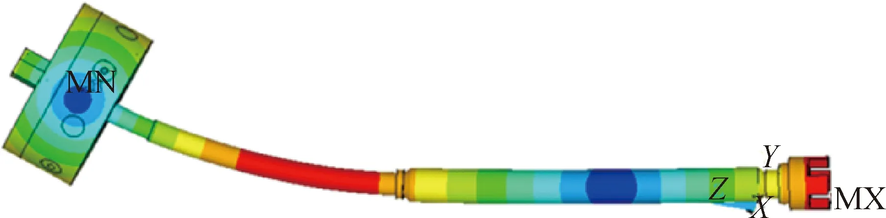
Fig. 6 First mode shape (140.64 Hz)
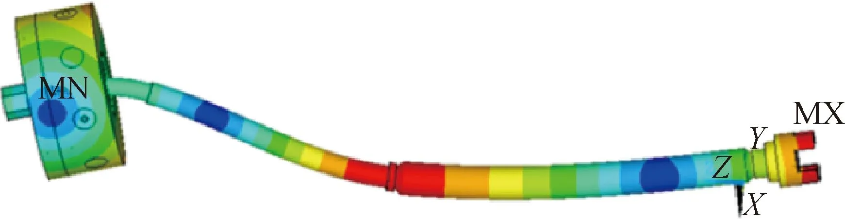
Fig. 7 Second mode shape (224.73 Hz)
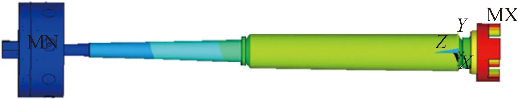
Fig. 8 Third mode shape (478.34 Hz)
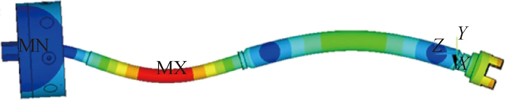
Fig. 9 Fourth mode shape (805.18 Hz)

Fig. 10 Fifth mode shape (1 270.30 Hz)
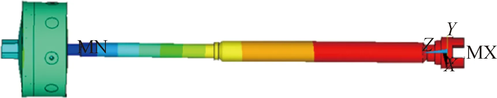
Fig. 11 Sixth mode shape (1 367.30 Hz)
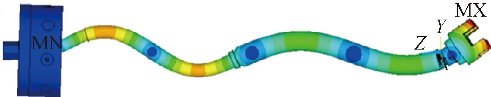
Fig. 12 Seventh mode shape (2 055.30 Hz)
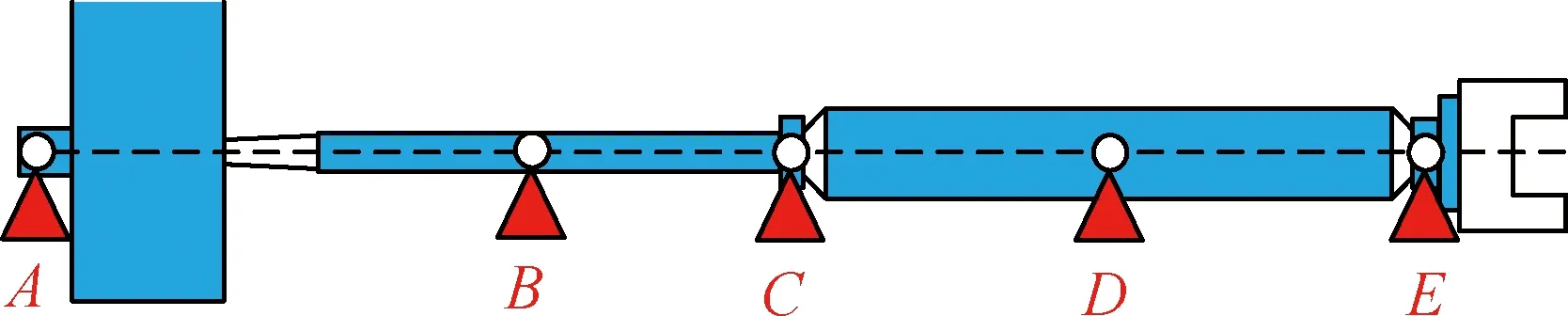
Fig. 13 Possible nodes of the HSFR
2.3 Appropriate node combinations of the HSFR
According to the actual design requirements of HSFR, the HSFR is supported by two bearings. PointsAandBare located at the position where the bearing cannot be installed. Therefore, pointsAandBare excluded.
Three node combinations are formed by combining pointsC,D, andEin pairs, as shown in Table 2. Each node combination is substituted into the frequency characteristic equation to calculate the first three critical speeds of HSFRSs, as shown in Table 3. The working speeds I and II are 15 000.0 r/min and 34 000.0 r/min, respectively. The second critical speed of COMB3 is close to the working speed I, so the COMB3 is excluded. The first three critical speed of COMB1 and COMB2 are not close to the working speeds. Therefore, COMB1 and COMB2 are appropriate node combinations.
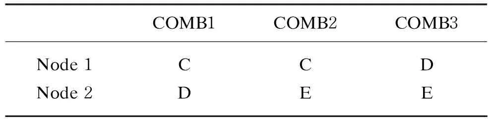
Table 2 Three node combinations
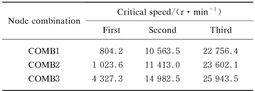
Table 3 First three critical speeds of HSFRSs under different node combinations
2.4 Vibration characteristics of the HSFRS
The dynamic model of HSFRSs is shown in Fig. 14. According to the COMB1 and COMB2, the vibration characteristics of the HSFRS under different working speeds are calculated. The time-domain vibration characteristics of the HSFRS at pointAfor different working speeds are shown in Figs. 15-18.
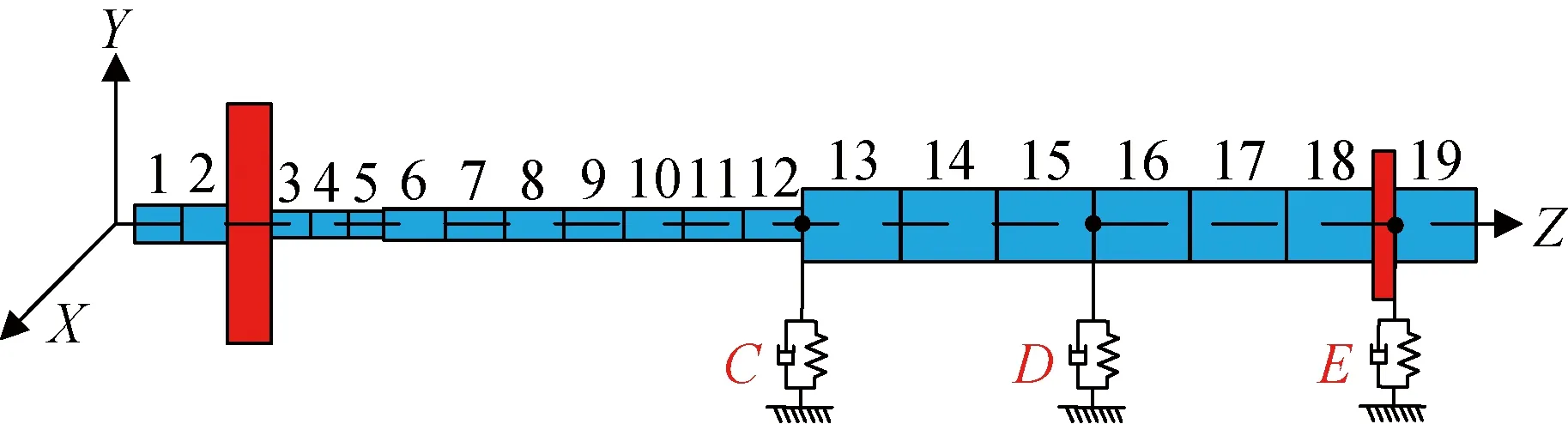
Fig. 14 Dynamic model of the HSFRS
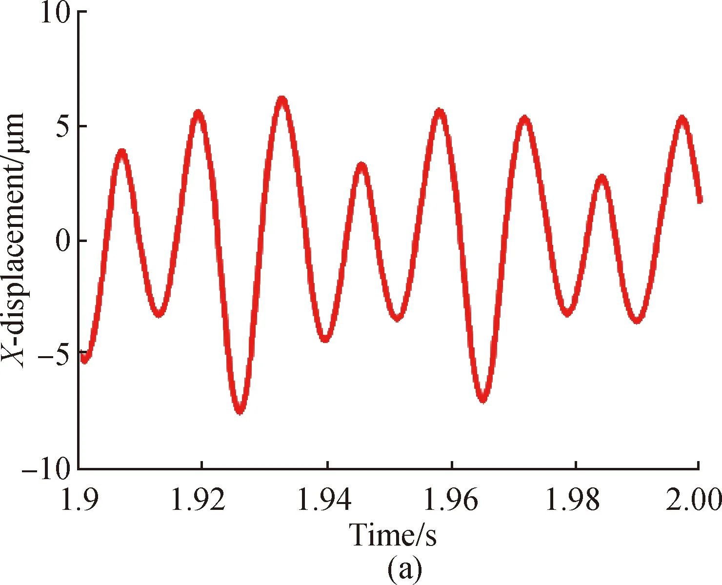

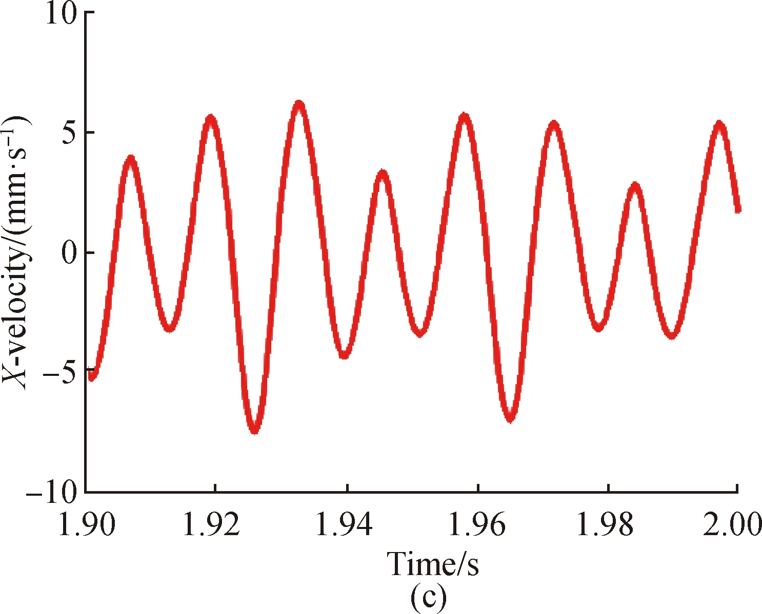
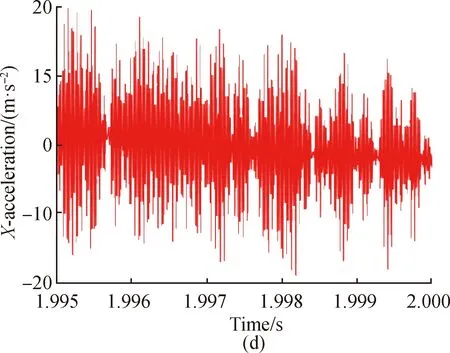
Fig. 15 Vibration responses of the HSFRS of point A in the X direction under the COMB1 at the working speed I: (a) displacement, (b) displacement spectrum, (c) velocity, and (d) acceleration


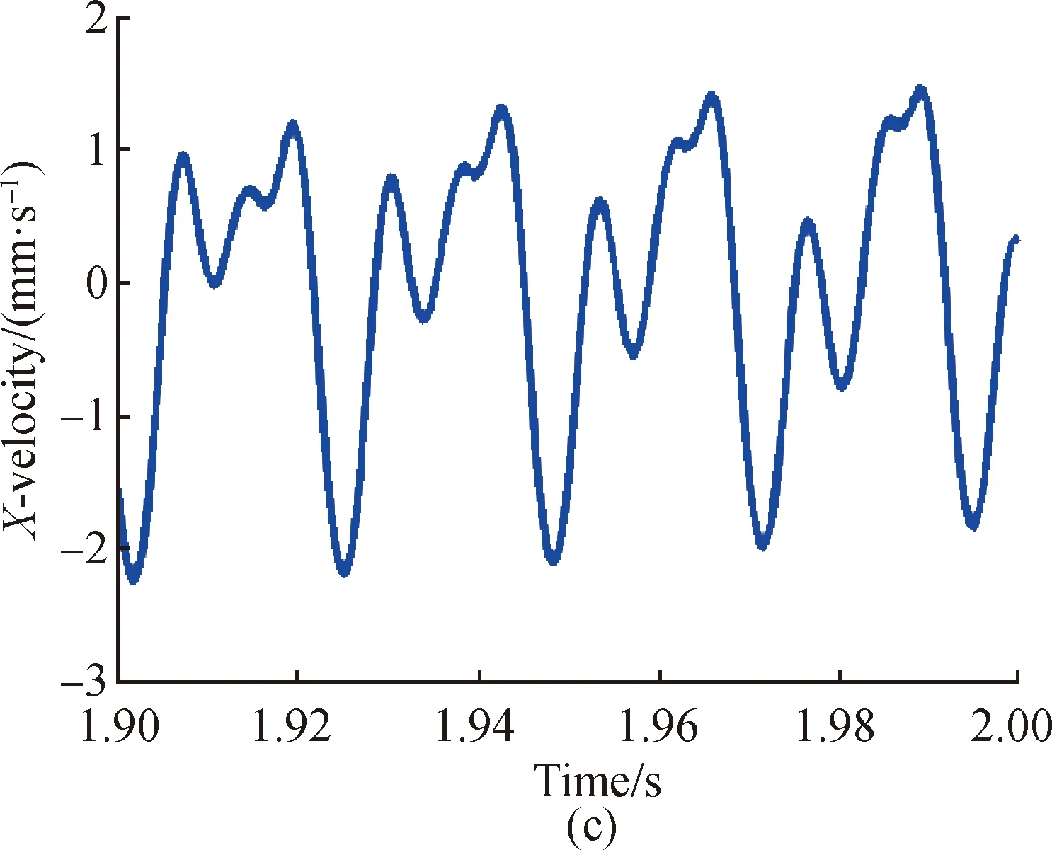

Fig. 16 Vibration responses of the HSFRS of point A in the X direction under the COMB2 at the working speed I: (a) displacement, (b) displacement spectrum, (c) velocity, and (d) acceleration
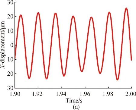
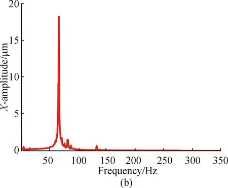

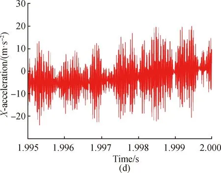
Fig. 17 Vibration responses of the HSFRS of point A in the X direction under the COMB1 at the working speed II: (a) displacement, (b) displacement spectrum, (c) velocity, and (d) acceleration

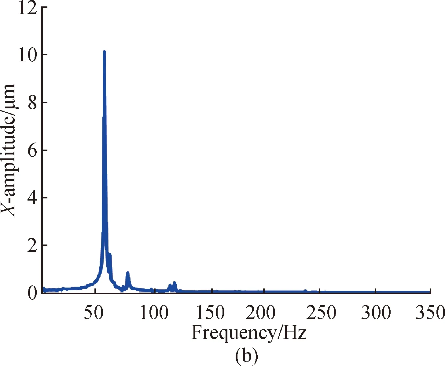
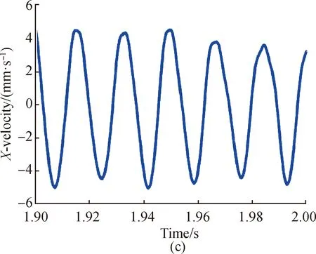
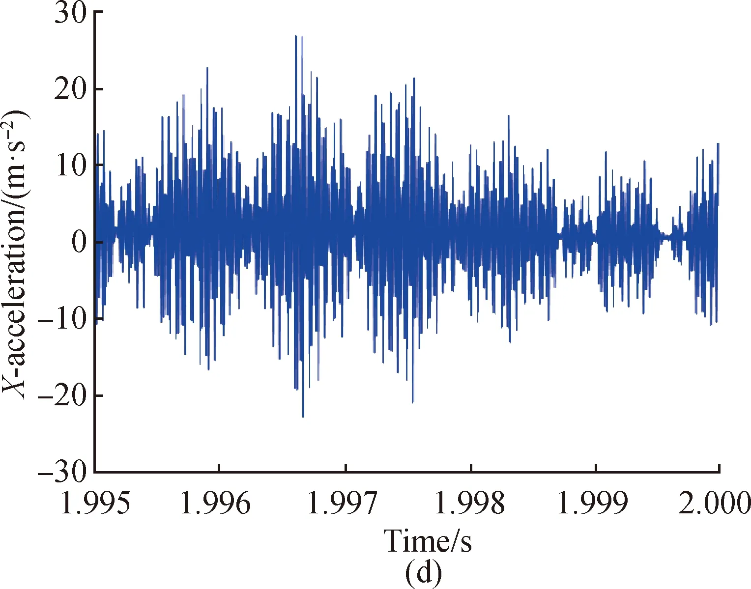
Fig. 18 Vibration responses of the HSFRS of point A in the X direction under the COMB2 at the working speed II: (a) displacement, (b) displacement spectrum, (c) velocity, and (d) acceleration
2.5 Dynamic analysis and optimal design
According to the vibration characteristics of the HSFRS under different node combinations, the RMS values of displacement(x), velocity(v) and acceleration(a) at pointAfor different working speeds under the COMB1 and COMB2 are compared, respectively, as shown in Table 4. For the working speed I of 15 000.0 r/min, the RMS values of displacement, velocity and acceleration at pointAunder the COMB1 are 7.84 μm, 3.42 mm/s and 8.10 m/s2and these under the COMB2 are 2.99 μm, 1.01 mm/s and 7.71 m/s2,respectively. For the working speed II of 34 000.0 r/min, the RMS values of displacement, velocity and acceleration at pointAunder the COMB1 are 15.77 μm, 6.77 mm/s and 9.37 m/s2and these under the COMB2 are 8.76 μm, 3.27 mm/s and 8.45 m/s2, respectively. The results show that the vibration characteristics under COMB2 are more stable than that under COMB1. Therefore, the COMB2 is selected as the optimal bearing support position for considering the stability of rotor rotation.

Table 4 RMS values of x, v and a at point A for different working speeds under the COMB1 and COMB2
3 Conclusions
To develop an optimization method of bearing support positions in the HSFRS based on the vibration characteristics, an optimization method of bearing support positions in the HSFRS is proposed. In this paper, the problem of optimizing bearing support positions in the HSFRS is solved by the developed optimization method.
(1) The first seven natural frequencies of the HSFR are basically consistent with the experiment values, so the FE model is effective.
(2) The natural frequencies, mode shapes and critical speeds of HSFRSs are obtained. Two node combinations are selected as appropriate node combinations.
(3) Vibration characteristics with two node combinations are analyzed. One node combination is selected as the optimal bearing position.
The results show that vibration amplitudes of HSFRSs are more stable when the bearing support positions are optimized. This study can provide a new method for optimizing bearing support positions of rotor systems.
猜你喜欢
杂志排行

Journal of Donghua University(English Edition)的其它文章
- Physicochemical Properties of Poly (Vinyl Alcohol)/Chitosan/Soluble Starch Composite Hydrogel
- Synthesis, Structure and Properties of a Novel Copolymer with Photochromic and Photoluminescence Functions
- Dynamic Modeling of Variable Stiffness and Damping for Spatial Linkage Weft Insertion Mechanism with Clearance
- Design and Lamination Process of Composite Fabric for Automobile
- Energy-Delay Tradeoff for Online Offloading Based on Deep Reinforcement Learning in Wireless Powered Mobile-Edge Computing Networks
- Design and Application of Coordinator App Based on Needs Survey