Dynamic Modeling of Variable Stiffness and Damping for Spatial Linkage Weft Insertion Mechanism with Clearance
2020-02-01LIBo李博HUKai胡凯JINGuoguang1WEIZhan魏展SONGYanyan1
LIBo(李博)1,2,HUKai(胡凯)1,2,JINGuoguang1,2,WEIZhan(魏展)1,2,SONGYanyan1,2
1 School of Mechanical Engineering, Tiangong University, Tianjin 300387, China 2 Tianjin Key Laboratory of Advanced Mechatronics Equipment Technology, Tianjin 300387, China
Abstract: In order to further analyze the influence of clearance on the kinematic performance of spatial linkage weft insertion mechanism, it is necessary to study the dynamic characteristics of contact impact force model with the variable stiffness and damping coefficient. Firstly, the parameters in the output process of the system are solved by describing of the flexible joint clearance. Then, based on Lankarani-Nikravesh contact force model, the contact impact stiffness and damping coefficient is modified from fixed values to time-varying coefficients. The dynamic model of spatial linkage weft insertion mechanism with modified clearance is established by Lagrange method, and the dynamic characteristics of the system are calculated. The results show that the joint clearance can directly affect the output performance of the mechanism. With the increase of the clearance value, the curve fluctuations of acceleration, driving torque and collision force are obvious, and it will be further intensified with the increase of spindle speed, which greatly affects the stability of mechanism and fabric quality. Finally, the virtual prototype is established by the SolidWorks software and simulated by the ADAMS software. The simulation results are compared with the numerical results, which verifies the accuracy of the modeling method in this paper.
Key words: rapier loom; spatial linkage weft insertion mechanism; clearance; contact impact force model; dynamic analysis
Introduction
A rapier loom is a shuttleless loom which is widely used at present. As one of the five core mechanisms of the rapier loom, the dynamic performance of weft insertion mechanism has a significant impact on the overall efficiency and fabric quality of the rapier loom. There are five kinds of common weft insertion mechanisms: variable pitch spiral weft insertion, differential gear weft insertion, electronic weft insertion, conjugate cam weft insertion and spatial linkage weft insertion. Among them, because of a small number of components and a high motion efficiency, the spatial linkage weft insertion mechanism has a high application value, and can realize a complex motion which is difficult to realize a by plane mechanism.
In the actual working condition, the joint clearance is inevitable. The existence of the clearance makes the actual motion of the mechanism deviate from the theoretical design trajectory, which reduces the kinematic accuracy of the mechanism, and even causes the failure and destruction of joint in serious cases. Therefore, it is necessary to study the influence of the mechanism of space link weft insertion on the output performance of high-speed rapier loom.
In recent years, many scholars at home and abroad have carried out research on the joint clearance problem of mechanisms, and achieved certain research results[1-3]. Wang and Wang[4]took the 4-SPS/PS parallel mechanism with transparent spherical joints as the research object. A clearance is introduced at one of the spherical joints of the parallel mechanism. The normal and tangential contact forces are estimated based on the Lankarani-Nikravesh contact force model and the modified Coulomb friction model respectively to analyze its dynamic characteristics. Cavalieri and Cardona[5]proposed a new three-dimensional rotational joint model with clearance. The non-smooth generalized α time integration scheme is used to fully satisfy the speed and position constraints without any user-defined penalty parameters. The effectiveness of the method is verified by a numerical example. Baietal.[6]proposed an optimal design method for reducing antenna vibration aiming at the problem of clearance connection in the double-axis driving mechanism of satellite antenna. The nonlinear spring damper model is used to establish the contact force model and the modified Coulomb friction model to verify the correctness of the method. Lietal.[7]used the nonlinear contact force model and the modified Coulomb friction model to consider the normal contact force effect and tangential friction effect at the gap joint respectively. The effect and interaction of gap connections are studied, which provides a basis for the analysis of the influence of the overall dynamic behavior. Maetal.[8-9]used a hybrid contact force model which is based on the Lankarani-Nikravesh contact force model and the elastic foundation model. Xiangetal.[10-12]combined the dynamic characteristics of mechanical system with clearance hinge and parameter sensitivity analysis method, and described the contact and collision process through continuous contact force model and modified friction model. Lou and Li[13]modified the Lankarani-Nikravesh contact force model by comparing a variety of contact impact force models, and studied the influence of clearance size, crank speed and friction on the acceleration of slider. Varedietal.[14-15]used a continuous contact force model to evaluate the contact forces, based on elastic Hertz theory together with a dissipative term. Moreover, using a contact model, the effects of working speed and clearance size on the dynamic characteristics of a planar mechanical system were analyzed and compared. Erkayaetal.[16-17]studied the dynamics of a partly compliant mechanism with joint clearance. Marquesetal.[18]took the crank slider mechanism as the research object, established a spatial rotation joint model considering both axial clearance and radial clearance, and analyzed the dynamic response of the system. Lietal.[19]proposed a methodology to investigate the kinematic accuracy and dynamic performance of space deployable mechanism with joint clearance while considering parameter uncertainty. Bai and Sun[20]carried out a numerical calculation on the dynamic model of the complex multi-body mechanical system with clearance, and described the dynamic characteristics of the system with multiple clearance pairs.
To sum up, the existence of clearance has a great influence on the output of the mechanism[21-24]. In this paper, based on the consideration of flexible joint clearance and collision energy dissipation, the clearance contact force model is modified and embedded into the Lagrange dynamic model of the mechanism. The dynamic model is numerically simulated by MATLAB software, and the virtual prototype of the system is established by ADAMS software. Through comparative analysis, the correctness of the established model is verified. The correctness of the model lays a theoretical foundation for the wear research and performance evaluation of high-speed rapier loom.
1 Operation Principle of Spatial Linkage Weft Insertion Mechanism
The sketch of the spatial linkage weft insertion mechanism is shown in Fig. 1. It is composed of three parts, including spherical 4R mechanism, plane four-bar linkage and amplification mechanism. Among them, the spherical 4R mechanism includes weft insertion mechanism box, transmission crank, spatial linkage and cross rocker. The plane four-bar linkage includes cross rocker, connecting rod and sector gear. The amplification mechanism includes sector gear, transmission pinion, rapier gear and rapier rack.

0-weft insertion mechanism box; 1-transmission crank;2-spatial linkage; 3-cross rocker; 4-connecting rod; 5-sector gear; 6-transmission pinion;7-rapier gear; 8-rapier rack.Fig. 1 Diagram of spatial linkage weft insertion mechanism
The motion mode is as follows: the motor drives the transmission crank to rotate around the axisA, and the transmission crank drives the spatial linkage to rotate at a fixed point. Under the constraint of the frame, the cross rocker drives the rockerOEto do reciprocating swing. The connecting rod drives the sector gear to move around the fixed axis ofGpoint. After the motion amplification of the transmission pinion and the rapier gear, it is transmitted to the rapier rack to make the end of the rapier belt move in a reciprocating straight line to complete the weft insertion action.
2 Description of Joint Clearance Model
2.1 Analysis of clearance collision state
In the ideal situation, the center of the moving auxiliary journal and the bearing are completely coincident. However, in the actual situation, a certain amount of clearance is necessary in order to realize the relative movement of the journal and the bearing.
There are two methods to describe joint clearance: rigid hinge and flexible hinge. Rigid hinge describes collision as two states, namely a free motion state and a collision state. Flexible hinge describes collision as three states, as shown in Fig. 2, namely a free movement state, a collision state and a continuous contact state. In this paper, the three-state method is used to describe the clearance.
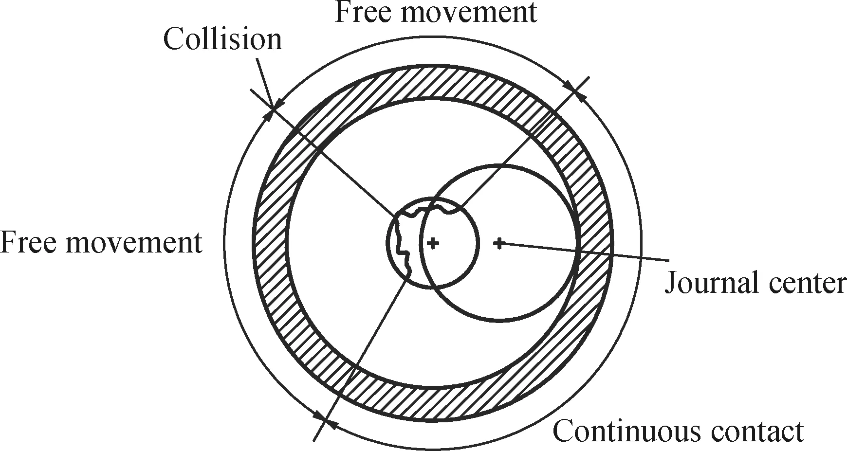
Fig. 2 Description of the motion state of the journal
2.2 Mathematical model of joint clearance
In order to facilitate the dynamic analysis of the system, the collision model of the spatial linkage weft insertion mechanism with joint clearance is established. As shown in Fig. 3, componentiand componentjare connected by rotating joint clearance. The centroids of componentiand componentjare respectively recorded asOiandOj, the volume coordinate system isXY, and the inertial coordinate system isXY, wherePiandPjrepresent the center positions of bearing and journal, respectively.

Fig. 3 Kinematic pair of multi-body system with joint clearance
In the working process of the mechanism, the collision between the shaft and the bearing is eccentric collision, and the collision speed is the combined speed of normal speed and tangential speed in the process of collision. When the collision occurs, the collision force is introduced into the dynamic equation of the system as a generalized force.
As shown in Fig. 3, the eccentricity vectoreof the bearing and the shaft can be expressed as
(1)
(2)
whereAiandAjare the coordinate transformation matrices of the volume coordinate system relative to the inertial coordinate system.siandsjare the position vectors of pointPin local coordinate systemxkyk(k=i,j);riandrjare the position vectors of the centroid of the bearing and the shaft in the inertial coordinate systemXY.
Akcan be expressed as
(3)
whereθkis the rotation angle of componentkin the volume coordinate system(k=i,j).
The eccentricity can be expressed as
(4)
The normal unit vector of bearing and journal collision can be expressed as eccentricity, which is shown as
(5)
When the shaft and the bearing are in contact with each other, the contact position will produce elastic deformation, that is, the penetration depth. Puncture depthδcan be expressed as
δ=eij-c,
(6)
wherecis the radius difference between the journal and the bearing.
(7)
whereRiandRjare the bearing radius and the journal radius respectively.
The velocities of impact pointsQiandQjrelative to the inertial coordinate systemXYcan be obtained by calculating the first derivative of Eq. (7) for time.
(8)

(9)
By substituting Eq. (8) into Eq. (9), we can get
(10)

Fig. 4 Puncture depth caused by collision between journal and bearing
At the position of the collision point, the relative velocity is projected to the tangent direction and normal direction of the collision surface respectively, and the relative tangential velocityVTand the relative normal velocityVNcan be obtained. As shown in Fig. 5, the relative normal velocity determines the contact and separation state between the colliding bodies, and the relative tangential velocity determines the relative sliding or viscous motion between the colliding bodies. Therefore,VTandVNcan be used to judge the relative motion state of the journal and bearing in the joint clearance.

Fig. 5 Velocity vector diagram of collision point
The relative normal velocity and the relative tangential velocity are respectively
(11)
where the tangential unit vectortis obtained by rotating the normal unit vectornby 90° counterclockwise.
Meanwhile, forces and moments acting on the memberk(k=i,j) are shown in Fig. 6.

Fig. 6 Force vector diagram of collision point
For componenti,
(12)
for componentj,
(13)
3 System Dynamics Modeling
3.1 Establishment of contact force model with variable stiffness damping
On the premise of flexible hinge clearance collision, the impact force can represent the kinetic energy loss after collision and the system energy loss caused by internal damping. Combined with the expression of lag damping factor given by the law of conservation of energy, the kinetic energy loss ΔEof the system after collision can be expressed as a function of recovery coefficient and initial collision velocity
(14)
The above energy loss can also be obtained by the formula composed of hysteresis damping factor, stiffness coefficient and initial collision velocity
(15)
Substituting Eq. (14) into Eq. (15), the hysteresis damping factor is
(16)
whereKis the contact stiffness.
The calculation formula is
(17)
whereσiandσjare material related parameters. And the calculation formula is
(18)
whereνlis the Poisson’s ratio of the material andElis the elastic modulus of the material (l=i,j).
The relationship between damping coefficientDand puncture deformationδis
D=χδn.
(19)
Thus, the corresponding contact force model can be established as
(20)

Equation (20) is the Lankarani-Nikravesh contact force model. Through the analysis of Eqs. (16) and (20), it can be seen that the stiffness coefficient of Lankarani-Nikravesh contact force model ignores the coupling relationship between penetration depth and contact stiffness, which is more suitable for the contact problems with large clearance and small load. In addition, the application range of damping coefficient is limited by the recovery coefficient, which is only applicable to the restoration when the complex coefficient is large.
Based on the improved elastic foundation model in Ref. [25], the relationship between load and penetration depth is obtained as
(21)
whereE*is the elastic modulus of the material and ΔRis the radius difference between the journal and the bearing.
In Ref. [26], the time-varying nonlinear contact stiffness coefficient and contact damping coefficient are proposed, which include the penetration depth, initial impact velocity and recovery coefficient
(22)
(23)
Taking the clearance value of 0.01 mm and the rotation speed of crank shaft at 500 r/min as an example, the curves of contact stiffness and contact damping varying with the change of penetration depth and crank angle can be obtained. It can be seen from Fig. 7 that at the beginning of a collision, the contact stiffness increases rapidly with the deepening of penetration depth. When the penetration depth reaches 0.005 mm, the increasing trend of contact stiffness slows down. At the same time, it can be seen from Fig. 8 that the contact stiffness has a relatively stable range for a long time in the case of small clearance value. It can be seen from Fig. 9 that there is a nonlinear relationship between the penetration depth and the damping coefficient before 1.5×10⁻²mm, and then it is closer to the linear relationship.

Fig. 7 Curve of contact stiffness with penetration depth
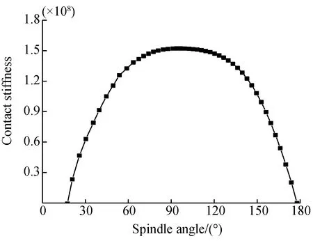
Fig. 8 Curve of contact stiffness with time

Fig. 9 Curve of contact damping with penetration depth
From Eqs. (20)-(23), the improved contact force model can be obtained as
(24)
3.2 Solution of dynamic parameters of members with clearance
As shown in Fig. 10, the origin of the fixed coordinate system is established at the intersectionOof the four rotating auxiliary axesA,B,CandD. The vertical plane points to the outside as thex-axis, and they-axis along theOGdirection and thez-axis perpendicular to theOGdirection. The fixed coordinate systemOxyzis established, and the dynamic coordinate systemsOx0y0z0,Ox1y1z1,Ox2y2z2, andOx3y3z3are established on the corresponding components.α1-α8are the angles between the center of mass of each component.θ1-θ8are the rotation angles of each rotating joint.S1-S8are the centers of mass of each component.r1-r8are the lengths from the center of motion pair of each component to the center of mass of component. The clearance exists in the rotating joint atE, where the eccentricity vector angle isθr, and the eccentricity vector size is represented byr.
(25)

Fig. 10 Diagram of spatial four-bar weft insertion mechanism

According to the closed loop vector equation
LOEeiθ4+reiθr+LEFeiθ5+LFGeiθ6+LOG=0
(26)
(27)
where
a=LOG-LOEcosθ4-rcosθr,
b=LOEsinθ-rsinθr,
whereLOE,LEF,LFGandLOGare the lengths of corresponding rodOE,EF,FGandOGrespectively.
It can be sorted out
(28)
(29)
The derivation of Eqs. (28) and (29) for time can be obtained
(30)
(31)
(32)
(33)
m5glS4cosθ5+F′nLEFsin(θr-θ5),
(34)
(35)
wherelS4andlS5are the lengths from the center of rotation to the center of mass of the member 4 and 5 respectively;JE5andJG6are the inertia moments of the joint clearance to the mass center of the component.
3.3 Dynamic modeling of the spatial linkage weft insertion mechanism
Further analysis of the space link weft insertion mechanism is shown in Fig. 10, according to the coordinate transformation method, the transformation matrix used to transform from coordinatejto coordinateiis
(36)
According to the kinematic relationship between the components, the position coordinates of the centroid of each component can be obtained as
(37)
(38)
(39)
(40)
(41)
(42)
(43)
whered5,d6andd7are the radii of dividing circle of sector gear, transmission pinion, and rapier gear respectively; [C00] is the coordinate transformation matrix fromOx0y0z0toOxyz; [C01] is the coordinate transformation matrix fromOx1y1z1toOxyz; [C12] is the coordinate transformation matrix fromOx2y2z2toOx1y1z1.
For general plane motion, kinetic energy includes kinetic energy moving with the center of mass and kinetic energy rotating around the center of mass.
(44)
whereiis the label of each member in plane motion in the mechanism, andi≠2;miis the mass of componenti;Jiis the inertia moment of componentirelative to its mass centerSi;viis the centroid velocity of memberiandωiis the angular velocity of componenti.
Because of the spatial rotation of member 2, Euler angle should be introduced to calculate its kinetic energy. The expression is
(45)
whereJxx,JyyandJzzare the inertial coordinates of the spatial connecting rod pairx2,y2andz2respectively.Jxy,JyzandJzxare the products of inertia of the spatial connecting rod to the corresponding coordinate axis.ωx,ωyandωzare the angular velocities of the member rotating around the axesx,yandzrespectively.
To sum up, the expressions of total kinetic energyTand total potential energyUof spatial 4R mechanism, planar linkage mechanism and gear amplification system are
(46)
(47)
In this paper, the rotation angleθ0of the crank shaft is selected as the generalized coordinate, and the friction between the kinematic pairs and the deformation of the bar is not considered. By substituting Eqs. (46) and (47) into the Lagrange equation, the expression of the driving torque of the mechanism is
(48)
The solution flow chart is shown in Fig. 11.tis the time variable, Δtis the integral time step,tendis the set time length.

Fig. 11 Solution flow chart
Firstly, the geometric parameters of the mechanism are input to solve the position, velocity of the mass center of each component and the angular velocity of rotation around the center of mass. At the same time, whether the mechanism is in free or contact state is judged according to the embedded depth at the clearance. And the motion equation of the mechanism is further solved.
Secondly, the total kinetic energy and total potential energy of the system are further calculated according to the position and velocity of the mass center of each component and the angular velocity of rotation around the center of mass.
Finally, the motion equation, the total kinetic energy and the total potential energy of the mechanism are substituted into the Lagrange dynamic equation. If the conditions are satisfied, the results will be output, otherwise the program will continue to run.
3.4 Calculation and analysis of dynamic model
The geometric parameters and values of a certain type of spatial linkage weft insertion mechanism are shown in Table 1.

Table 1 Geometric parameters and values of each component of weft insertion mechanism
Take the clearance values as 0.01, 0.25 and 0.50 mm respectively, and set the rotational speed as 400 r/min. Substitute the parameters in Table 1 into Eqs. (36)-(49), and conduct numerical calculation by MATLAB. The kinematic variation curves of output parameters under different clearance values can be obtained, as shown in Fig. 12.

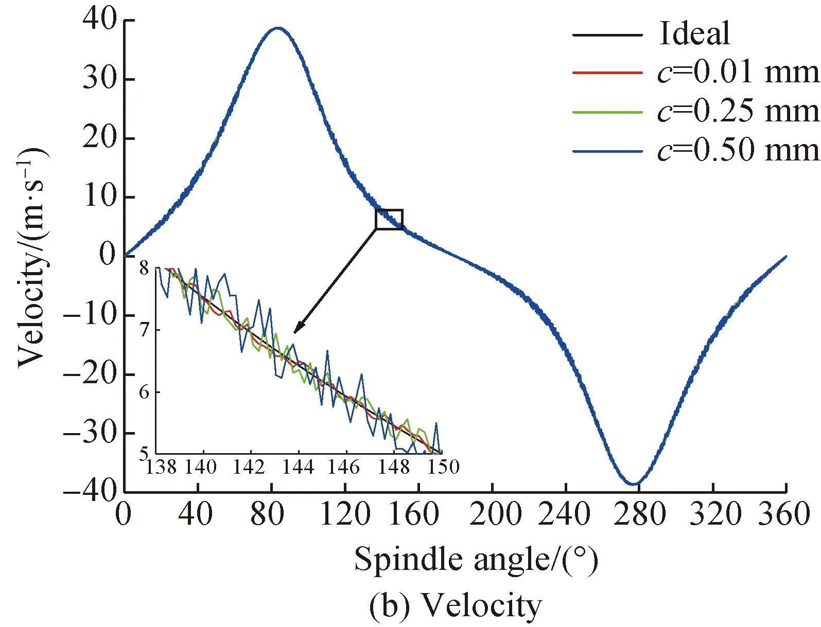
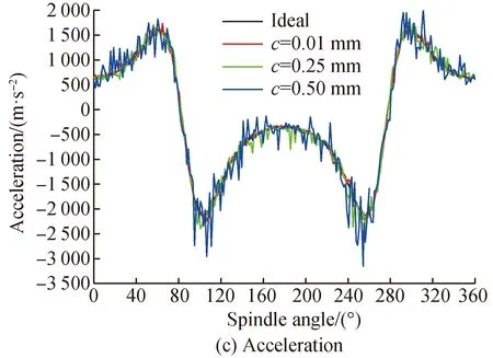

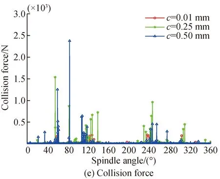

Fig. 12 Output characteristic curves of rapier belt under different clearance values
Combined with the weft insertion production process and Fig. 12, it can be seen that the clearance has little effect on the final output peak value of the rapier belt. When the crank angle changes from 60° to 105°, the rapier belt drives the rapier head to feed the yarn, and the speed of the rapier belt presents the characteristics of “fast forward”. Through the analysis of the acceleration in this interval, it can be judged that the clearance has a relatively small impact on the yarn feeding motion. When the crank angle changes from 105° to 255°, the weft insertion rapier head and weft insertion rapier head start to hand over, and the speed curve of rapier belt is relatively gentle. However, the acceleration curve fluctuates in a large range, and the clearance will have adverse effects on the smooth weft connection of the mechanism. When the crank angle changes from 255° to 300°, the weft insertion mechanism drives the rapier head in the return phase, and the speed curve shows the characteristics of “quick return”, and the acceleration curve of the rapier belt fluctuates slightly. When the crank angle changes from 300° to 360° and 0° to 60°, the loom will pick up the yarn again and prepare to enter the shed again. At this time, the acceleration curve fluctuates greatly, and the clearance between the joints has a negative effect on the accurate clamping of weft by the rapier head. It can be seen from Fig. 12 (c) that high frequency oscillation occurs near the maximum acceleration value of the curve, that is, near the maximum value and zero value of the corresponding speed curve. At this time, the force direction of the mechanism changes, which has a great impact on the mechanism, to affect the mechanical properties and output accuracy of the mechanism.
Through the analysis of driving torque, collision force and embedded depth, it can be seen that when the clearance value is small, the collision between journal and bearing is severe. With the increase of clearance in a small range, the collision force amplitude will increase correspondingly, and the time of contact between the secondary journal and the bearing increases. In Figs. 12 (d)-(f), the driving torque fluctuates at a relatively high frequency near the maximum value and zero value of the velocity curve. However, the amplitude of the corresponding collision force and the embedded depth curve can reach the maximum value. The larger the clearance, the higher the collision strength. And when the speed direction changes, the maximum embedded depth will produce severe collision, which has a significant collision on the output of the mechanism. At this stage, the force direction of the mechanism changes suddenly, which brings impact to the joint of the mechanism, further affects the dynamic performance of the belt mechanism, and even makes the mechanism fail.
In order to further study the influence of rotating speed on the dynamic performance of the system, the clearance value is taken as 0.25 mm, and the spindle speed is set at 300, 500 and 800 r/min. The output characteristic curves of the rapier head are shown in Fig. 13.
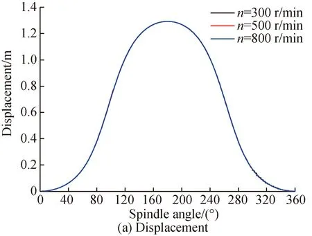

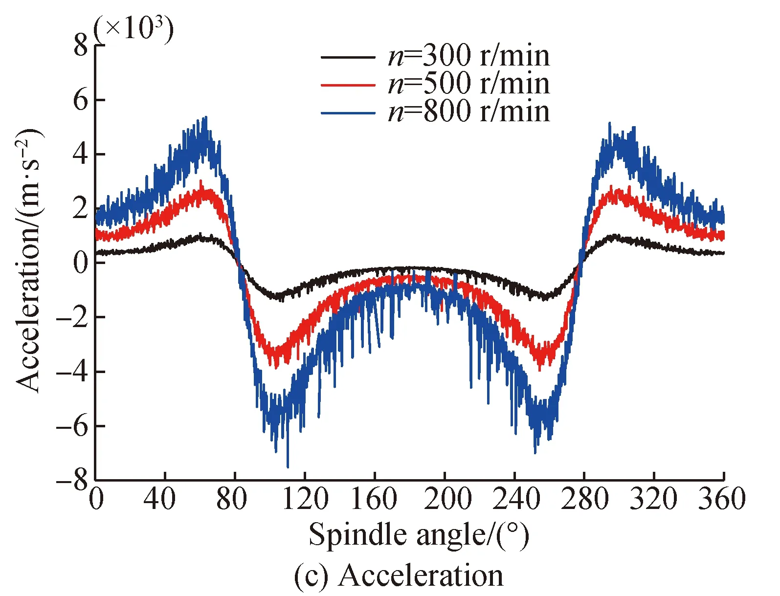

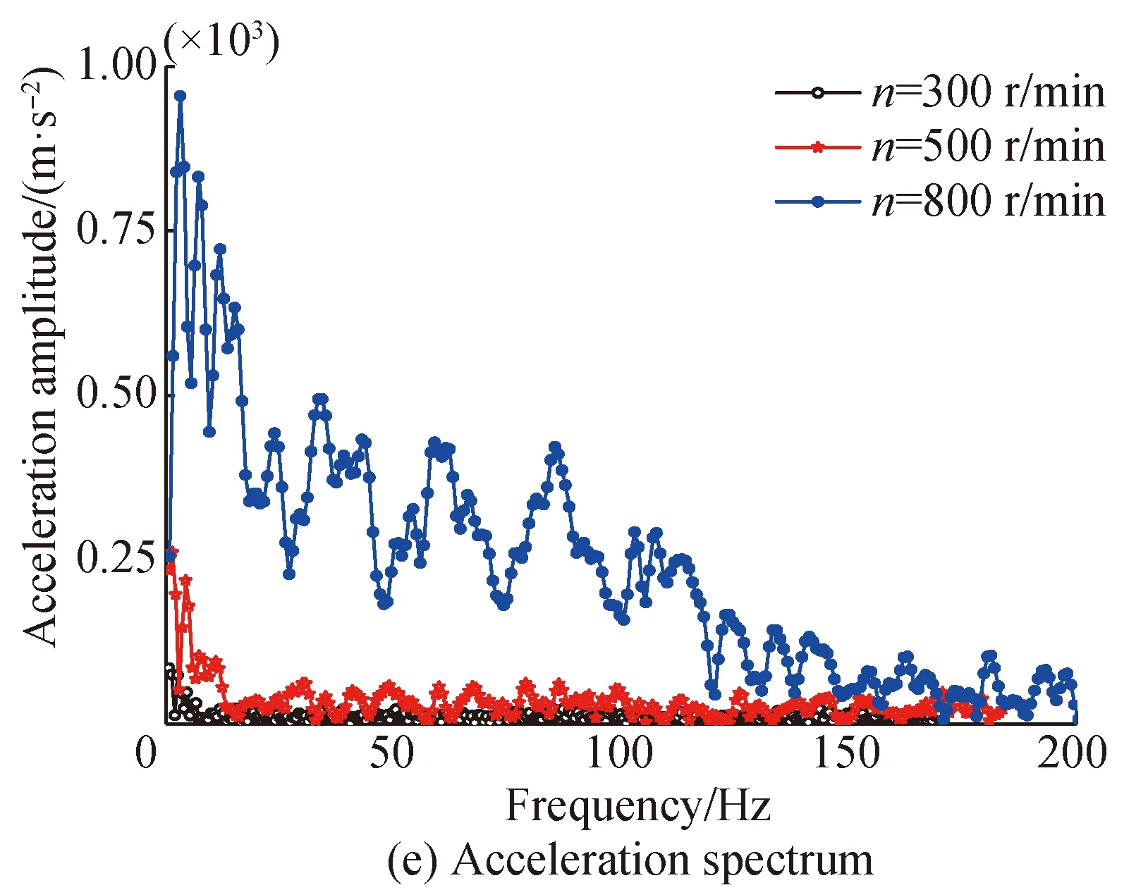
Fig. 13 Comparison of output characteristic curves at different speeds(c = 0.25 mm)
It can be seen from Fig. 13 that when the clearance value is fixed, with the increase of crank shaft speed, the curve movement trend does not change. However, the amplitude fluctuation changes. The higher the speed is, the higher the amplitude is, and the more obvious the amplitude fluctuation of acceleration and driving torque curve is. The driving torque and acceleration amplitude of 800 r/min crank shaft are 2.0 times and 1.9 times of 500 r/min respectively. As shown in Fig. 13(c), the collision force of the rapier head on the yarn increases sharply, resulting in a high weft breaking rate, which reduces the weft insertion efficiency of the loom. The sharp change of the acceleration has a great impact on the flat and stable weft connection of the mechanism and the pick-up of the yarn by the loom. If the rapier belt acceleration fluctuates greatly during this period, the weft can not be handed over and the working efficiency of weft insertion mechanism will be reduced. In addition, from the analysis of acceleration spectrum, it can be seen that the main frequency fluctuation is between 0 and 10 Hz. With the increase of speed, the amplitude changes significantly, and the corresponding maximum amplitudes are 80.0, 255.0, and 977.5 m/s2, respectively. In addition to the main frequency, the corresponding derived secondary frequency fluctuation is also very obvious, and the relative motion of journal and bearing is more complex. In addition, the numerical value of contact collision force increases sharply, and the discrete force acts on the spatial mechanism, which increases the curve spike, and affects the stability of the system dynamic performance.
4 Data Acquisition and Comparison of Virtual Prototype
As shown in Fig. 14, the virtual prototype of spatial linkage weft insertion mechanism with clearance is established by SolidWorks software, which is imported into ADAMS software, and the mechanism model with clearance motion pair is established for dynamic simulation. The results are compared with the numerical calculation results. The local enlarged drawing of the clearance is shown in Fig. 15. The parameter values are shown in Table 1.

Fig. 15 Enlargement at clearance
The clearance value is 0.5 mm, the rotate speed is 400 r/min, and the obtained curves are shown in Fig. 16.


Fig. 16 Comparison of output characteristic curves (c=0.5 mm)
According to Figs.16(a) and (b), the modeling method in this paper has a high coincidence with the simulation results of virtual prototype for the displacement and speed of the rapier head. It can be seen from Figs. 16(c) and (d) that for the acceleration of the rapier head and the driving force of the crank shaft, the modeling method in this paper still has a high coincidence degree with the simulation results of the virtual prototype, and the corresponding maximum amplitudes are 1.035 times and 1.099 times of the virtual simulation curve, which are close to each other. However, the spike of the virtual prototype simulation curve is more obvious, and the curve solved by the modeling method in this paper is more than smooth. According to the comparison of the clearance collision force in Fig. 16(e), the difference between the modeling method and the virtual prototype simulation results in amplitude is small, but the fluctuation frequency is different. The main reason for the above phenomenon is that the variable step integration algorithm is used in the numerical calculation programming, and the continuity of the output curve is still maintained in some cases of sudden change. Therefore, the modeling method in this paper has high accuracy and effectiveness on the premise of ensuring the operation efficiency.
5 Conclusions
(1) In this paper, the modified Lankarani-Nikravesh contact force model is applied to the space link weft insertion mechanism with clearance. By introducing the time-varying contact stiffness coefficient and contact damping coefficient, the multi parameter coupling phenomenon in the clearance collision is described, so that the model has good applicability.
(2) The whole dynamic model of the spatial linkage weft insertion mechanism is established by Lagrange method, and the modified contact force model is embedded to solve the dynamic parameters such as the crank shaft driving torque.
(3) Through the analysis, the mechanism is more significantly affected by the joint clearance. With the increase of the clearance size and spindle speed, the output characteristics of the rapier belt change obviously, especially for the acceleration, driving torque and collision force.
(4) Through the comparison and analysis of the virtual prototype simulation and the established model, the coincidence degree of each characteristic curve is high, which verifies the correctness and effectiveness of the model.
猜你喜欢
杂志排行

Journal of Donghua University(English Edition)的其它文章
- Physicochemical Properties of Poly (Vinyl Alcohol)/Chitosan/Soluble Starch Composite Hydrogel
- Synthesis, Structure and Properties of a Novel Copolymer with Photochromic and Photoluminescence Functions
- Design and Lamination Process of Composite Fabric for Automobile
- Energy-Delay Tradeoff for Online Offloading Based on Deep Reinforcement Learning in Wireless Powered Mobile-Edge Computing Networks
- Optimization Method of Bearing Support Positions in a High-Speed Flexible Rotor System
- Design and Application of Coordinator App Based on Needs Survey