Bearing Fix for Large Sub-synchronous Vibration in Steam Turbine-gearbox-generator System
2020-01-18
(1.Rotor Bearing Solutions International,3277 Arbor Trace,Charlottesville,Virginia,22911,USA,paul.allaire@rotorsolution.com,2.tim.dimond@rotorsolution.com,3.jianming.cao@rotorsolution.com)
Abstract:An industrial high speed Siemens 12MW steam turbine operating at 10,700 rpm drives a Flender gearbox pinion, which is connected to a low speed gear shaft, with gear ratio at 17.1, driving a Siemens generator at 1,500 rpm (50Hz).Ahigh amplitude sub-synchronous vibration, at 0.89X, occurred in the high speed pinion at low motor electrical loads. The Zollern gearbox pinion bearings consisted of offset half two pad bearings which were found to be unstable,exciting one of the pinion-steam turbine shaft modes at the 0.89X frequency.Acontributing factor to the problem was an oil leak into the high speed coupling. Tilt pad bearings could not be used to fix the problem due to the limited available bearing space in the gearbox pinion. New pressure dam bearings with three pads and two pressure dams were designed to fix the problem. The bearings were implemented and the 0.89X high vibration problem was eliminated by the pressure dam bearing pinion bearing design. This paper describes the system rotor dynamic analysis and pressure dam bearing design process.
Keywords:Rotordynamics, Pressure Dam Bearings, Subsynchronous Vibration, Entrained Oil Excitation
Nomenclature
BgGear Tooth Thickness
BpPinion Tooth Thickness
bGear tooth width
EModulus of Elasticity
KgGear Tooth Stiffness
RgGear Pitch Radius
RpPinion Pitch Radius
αPressure angle
βHelix Angle
ψ Orientation Angle
0 Introduction
High vibration problems in rotating machinery often have a sub-synchronous vibration component to them.Often high speed shafts operating in fixed pad bearings have high cross coupled stiffness.In quite a few cases,a pressure dam or step fixed pad bearing can be used to stabilize the machine in a horizontal configuration,as shown by Allaire,et al(1979),Nicholas and Allaire(1980),Nicholas et al.(1980),and Flack et al.(1981).Another paper by Allaire et al(1986)[1-5]showed that the pressure dam bearing could also be used in a vertical machine.There are quite a few design parameters:
Number of Pads
Number of Dams
Location of Dams in Each Pad
Axial Extent of Dams
Compressors and steam turbines have been found to have sub-synchronous vibration problems which are often fixed with a bearing modification,as noted in Allaire et al.(1987)and Allaire et al.(1992)[6-7].Many advanced in modeling of pressure dam bearings have been published,as seen in He and Allaire(2002),He et al.(2002),and He et al.(2004)[8-10].Advances have also been made in geared systems,by Stringer et al.(2007)and Kaplan(2013)[11-12],such as the one in this work.This paper shows how this problem was fixed with a new,fixed pad pressure dam bearing.
1 Steam Turbine/Gear Box/Generator Case History
An industrial high speed Siemens 12 MW steam turbine operating at 10,700 rpm drives a Flender gearbox pinion,which is connected to a low speed gear shaft,with gear ratio at 17.1,driving a Siemens generator at 1 500 rpm(50Hz).The rotor train configuration is shown in Fig.1.

Fig.1 Steam turbine/gear box/generator configuration
A measured sub-synchronous vibration at 10 201 rpm-0.85X-occurred in the high speed pinion of the gear box,as shown in Fig.2 when the generator was operated at zero power output during the initial on-site start up.

Fig.2 Measured sub-synchronous vibration at 0.85X and operating speed at 1.0X.Vibration components in high speed pinion at zero generator load
The bearing loads are shown in Table 1 as the generator takes power and the operating speed increases.These bearing load values are used in the rotor dynamic analysis to come.

Tab.1 Bearing loads and angles as generator power output and speed increases
2 Gear Tooth And Gear Box Modeling
The numerical formula for the gear mesh stiffness is given in Eq.(1).It should be noted that the thrust loads on the gear system vanish due to the herringbone gear configuration,as shown in Fig.3.The herring bone gear properties are shown in Table 2.It should be noted that the herring bone configuration has two contact points so the gear stiffness has been multiplied by a factor of 2 in the following analysis.


Fig.3 Gearbox herringbone gear geometry

Tab.2 Gear mesh dimensions and contact angles
3 Full Rotordynamic Analysis of System
The original fixed pad bearings in the high speed pinion shaft were a 2-lobe offset half bearing,design as shown in Fig.4.
It was also discovered that there was on oil leak from the gearbox bearing into the flexible coupling between the high speed pinion and the steam turbine.To simulate the effect of the oil whirl,as shown in Fig.8,in the coupling,an estimated cross coupled value of 2.84×10⁷N/m was placed on the coupling location.An example of entrained oil effects is shown in Fig.5.This was included in the following rotor dynamic analysis.

Fig.4 High speed pinion shaft original 2 lobe offset halves bearing geometry

Fig.5 Entrained oil in rotor(Ehrich,1967)
The rotor dynamic stability analysis evaluated the system eigenvalues and eigenvectors for each rotor mode,up to 10 modes.The results are shown in Fig.6.Mode 4 has a frequency of 9 443 rpm and a log decrement of-0.911,which is unstable.This frequency is at 0.88X,or very close to the measured frequency of 10 201 rpm.The 4th mode shape is a conical mode as shown on Fig.6.All of the other modes have a positive log decrement,so they are all stable.

Fig.6 Mode shape and eigenvalues of rotordynamic stability analysis for load case 1 with original offset half bearings
The bearing load cases for all 8 loads and operating eccentricity is shown in Fig.7.For the loading case 1,the loads are zero in the horizontal direction(x)and very small in they-direction.This results in the pinion rotor operating eccentricity very near zero.This leads to the mode 4 instability as shown in Fig.6.

Fig.7 Original offset half bearing with operating eccentricity at load cases 1 through 8
4 New Pressure Dam Bearing Design
A new three lobe pressure dam bearing was designed.There are many design details involved in a pressure dam bearing,as given in the introduction.The general properties of fixed pad bearings are that they are normally have high cross coupled stiffness values when they operate near the bearing center with nearly zero eccentricity.Thus,bearings operating with nearly zero eccentricity are often operating in shafts that are unstable,as this one is.
The new pressure dam design objectives are
Use pressure dams to drive shaft vertically upward to increase eccentricity at low loads
Check to see if rotor is still stable at higher loads
Ensure predicted operating temperatures are within design limits
There was no room in the bearing housings for a tilting pad bearing so a fixed pad bearing needed to be designed.The new pressure dam bearing design predicted pressure profiles for load case 1 are shown in Fig.8.There is no pressure dam in the upper right pad,Pad 1.It is seen that two pressure dams are used in the left,Pad 2,and bottom pad,Pad 3.The maximum pressure values for each pad are Pad 1=249 psi,Pad 2=351 psi,and Pad 3=264 psi.The net result is that the rotor eccentricity is approximately 0.4.

Fig.8. Three lobe pressure dam bearing design and pressure on pads with operating eccentricity at load case 1
The rotor dynamic stability results are shown in Fig.9.The mode 4 now has a frequency of 11 404 rpm and a log decrement of 3.368,which is very stable.The 4thmode shape is a conical mode as shown on Fig.12.All of the other modes have a positive log decrement so they are all stable.

Fig.9 Mode shape and eigenvalues of rotordynamic stability analysis for laod case 1 with new pressure dam bearing
Figure 10 shows that the shaft operating eccentricity is approximately 0.7 for the load case 5.Thus,the pinion shaft is stable.The final design drawing for the three lobe pressure dam bearings is shown in Fig.11.It should be noted that many other dam configurations were considered in the design process.Figure 12 shows the pinion rotor eccentricity range of the pressure dam bearing over the bearing load range showing that the eccentricity is kept relatively large.

Fig.10 Three lobe pressure dam bearing design and pressure on pads with operating eccentricity at load case 5
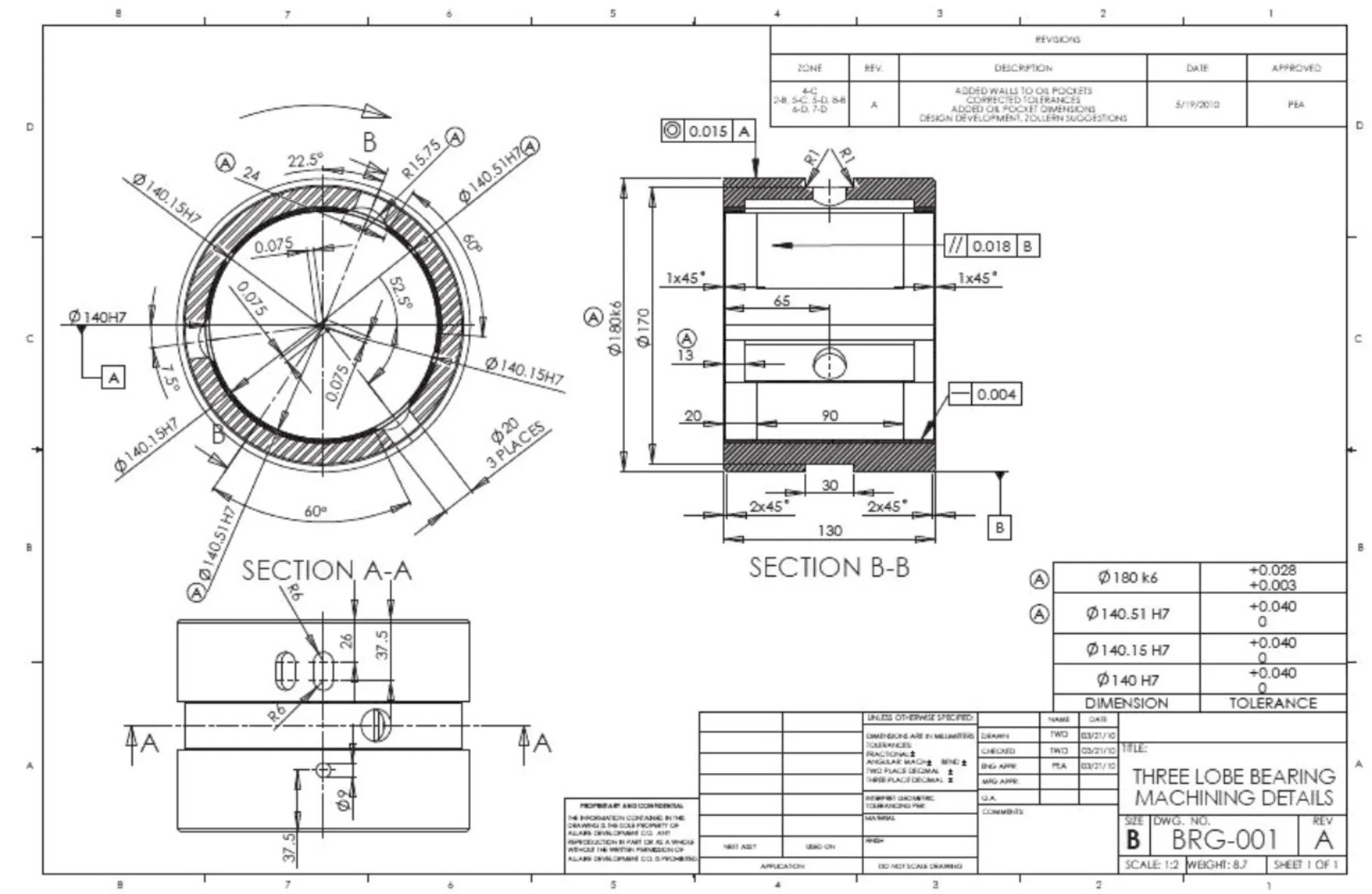
Fig.11 Design drawing for three lobe pressure dam bearing

Fig.12 Comparison of pressure dam bearing pinion shaft eccentricty with original bearing over load range
5 Conclusions
The results can be easily summarized as follows:
·Replaced Offset Half Bearing with New Optimized Pressure Dam Bearings
·Easily Fit into Existing Housing
·No Sub-Synchronous Instability atAny Load
·One Shot Permanent Fix
The optimum pressure dam bearing was very successful and the problem was solved permanently in one shot.An oil drain hole was placed in the coupling to remove the entrained oil issue but the end user wanted the bearings to be capable of remaining stable if the oil drain hole became clogged up.
6 Acknowledgements
Zollern Transmissões Mecânicas Ltda.and Siemens-MD-Flender are gratefully acknowledged for permission to present these results.
