Application and Configuration of High Power Motor-compressor Units Equipped with Active Magnetic Bearings*
2020-01-18
(1.Waukesha Magnetic Bearings,Suzhou,China.zguo@waukbearing.com,2.Shenyang Blower Works Group Corporation,Shenyang,China.sjwangyujing@shengu.com.cn,3.Waukesha Magnetic Bearings,Pawcatuck,USA.rshultz@waukbearing.com,4.Waukesha Magnetic Bearings,Worthing,UK.amasala@waukbearing.com)
Abstract:With the high reliability and high availability they provide, active magnetic bearings (AMBs) have found increasing application in high-speed and high-performance turbomachinery. The oil& gas and energy industries represent core markets for AMB products and have been at the forefront of their deployment and innovation over the past three decades, driving the development of international standards for AMB-equipped turbomachinery.Typical machinery equipped with AMBs include electric motors and generators, centrifugal compressors, turboexpanders,blowers, and pumps.Among these, high-power motor-compressors have become a major application field for AMBs in the oil&gas industry over the past two decades.
Keywords:Active Magnetic Bearing,Motor,Compressor,Integrated Motor-compressor,Vessel Compressor Line,Oil&Gas
Nomenclature
AMB Active magnetic bearing
MC Motor-compressor
VCL Vessel compressorline
0 Introduction
Over the past two decades,high-power motor-compressors for the oil&gas industry have represented a major field of application for active magnetic bearing(AMB)systems(Jayawant,1997,Kasarda,2000,Kummlee,et al,2000,and Sietinga,et al,2008)[1-4].Challenging operating conditions,gas compositions and operating environments have continually set new requirements for motor-compressor applications,driving the advancement of AMB technology(Masala,et al,2013,Swann et al,2014,Al-Aidarous&Shultz,2014,Guo,et al,2016)[5-8].Subsea and sealed motor-compressors operating with sour gas represent some of the leading-edge applications.At the same time,the deployment and innovation of AMB product in the oil&gas and energy industries also drives the development of international standards for AMB-equipped turbomachinery(ISO,2002,2004,2006,2012,andAPI,2014)[9-13].
Based on the combined experience of authors’companies in AMB and compressor design and operation,this paperaddresses some of the key technical challenges,solutions and benefits associated with the application of AMB systems in motor-compressors.Special focus is put on high-power integrated motor-compressors.The design scheme and technical considerations driving the development o a new hermetically sealed motor-compressor equipped with anAMB system are also discussed in detail.
1 Levels of Complexity
AMB systems are typically applied to single or multiple shaft compressor trains with direct-drive configurations and variable speed ranges.The presence of a gearbox and its associated lubrication system normally leads to the use of conventional oil-film bearings for both the driver and the driven machine.
In a direct-drive centrifugal compressor configuration,the driver can be either a gas or steam turbine or an electric motor.Depending on the type of driver and the level of integration between the driver and driven machine,different levels of complexity exist for theAMB system(Figure 1).
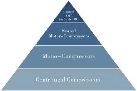
Fig.1 Levels of complexity for AMB-equipped compressors,with the bottom level being the least complex
1.1 Turbine-driven Centrifugal Compressors
The least complex configuration is a standalone centrifugal compressor supported by an AMB system and driven by a steam or gas turbine running on conventional fluid film bearings.This hybrid bearing solutionis popular among large OEMs and end-users in Russia and has been successfully applied in more than a hundred high-power centrifugal compressors for pipeline or boosting service.A lubrication system is still required for the turbine bearings,but the application of AMBs on the compressor reduces the overall equipment volume and associated maintenance.The increased operating flexibility gained with the active magnetic bearings and the capacity to start the machine within a few minutes(normally less than two),and with limited or no operators on-site,represent additional benefits of this configuration for remote locations and extreme ambient temperature conditions.
An 18MW gas turbine-driven,AMB-equipped compressor(Figure 2)that has been in operation since 2013 has an outstanding track record of 98%availability.The AMB hardware is fitted inside the compressor casing but separated from the process gas by dry gas seals.The AMB hardware is purged by a continuous flow of low-pressure clean air(1.2 to 1.3 bar-a)that serves the double purpose of evacuating the heat generated in the AMB cavities and pressurizing the AMB housing to meet the EEx-p certification requirements for hazardous area operation.
1.2 Motor-compressors
The electric-motor-driven compressor is a natural application for AMB systems,as it can fully exploit the available benefits.When the electric motor and the compressor are in separate casings and are connected with a flexible coupling,the two machines can be treated as standalone units in the AMB system design and operation.The presence of the flexible coupling separates the dynamics of the two machines,and overall the AMB system’slevel of complexity is equivalent to the complexity in astandalone compressor driven by a steam or gas turbine.In the simplest configuration for the motor-driven compressor,each machine has an independent,separately housed AMB controller.
An increased level of complexity is normally experienced when the AMB controllers are housed in a single enclosure and some auxiliary systems,such as the UPS and transformers,are shared by the AMB controllers of the two machines.The benefits,however,in terms of footprint reduction and overall cost reduction justifies the manageable increase of complexity deriving from the integration effort.
The level of complexity is further increased when the AMB controls of the two machines are integrated into a single AMB controller.In a 23MW motor-compressor train which has been in operation since 1998(Figure 3),both the high-speed synchronous motor with exciter and high-speed centrifugal compressor are equipped with active magnetic bearings.The AMB system has 11 control axes,six for the motor and five for the compressor,and a single AMB controller manages the entire train dynamics,as well as the data storage and communication functions.On high-powermotor-compressors like this,having a single AMB controller improves reliability while reducing the footprint and both capital and maintenance costs.

Fig.2 AMB-equipped compressor driven by a gas turbine
Due to the development or customization costs,the single,integrated controller design is typically only justified when a high number of units(10 or more)with same characteristics are required.With a limited number of units,or where some degree of customization of the electrical interfaces is required,a system integration at enclosure and auxiliary system level only is more appropriate.Having separate AMB controllers provides customers the opportunity to run the two machines independently and in different locations,for instance at the compressor and motor vendor workshops during internal factory acceptance tests and rotor balancing.This becomes a key factor in projects with short lead times.Another advantage of using separate controllers in a single enclosure is the opportunity to fit a spare AMB controller into the enclosure(Figure 4).When maintenance of one controller is required,the spare controller can readily replace the out-of-service controller,reducing machine downtime and increasing overall availability of the unit,as compared to a configuration with a single AMB controller for the entire motor-compressor.
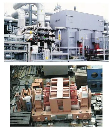
Fig.3 23MW motor-compressor supported by an 11-axis AMB system
1.3 Hermetically Sealed Motor-compressors
Within the larger category of motor-driven compressors,the ability of AMBs to operate within a pressurized gas environment has allowed the development of hermetically sealed motor-compressor units(Figure 5),where the entire shaft and the AMB hardware are immersed in the process gas and surrounded by the compressor and motor casing.The compressor and motor may be designed with a common shaft or separate shafts connected through rigid or flexible couplings.
On hermetically sealed(also known as integrated)motor-compressor units,compressor configurations with two,three or four radial AMBs have been developed over the past two decades to meet specific compressor bundle,power and rotordynamic performance requirements.Typically,four radial bearings are used on motor-compressor configurations with the compressor and motor shafts connected by a flexible coupling.A three-bearing configuration is typically used on split compressor and motor shafts connected with a rigid coupling.Two radial bearings are typically used when motor and compressor are on a single shaft.
Machine configurations may also differ in the number of compressor stages(i.e.,single or multiple stage),position of the thrust AMB(i.e.,between the two machines or on the compressor non-drive-end),or machine orientation(i.e.,vertical or horizontal).
Among AMB designs for hermetically sealed motor-compressors,the canned AMB solution(Figure 6)is the summit of complexity,the reasons for which will be further addressed in the subsequent sections.
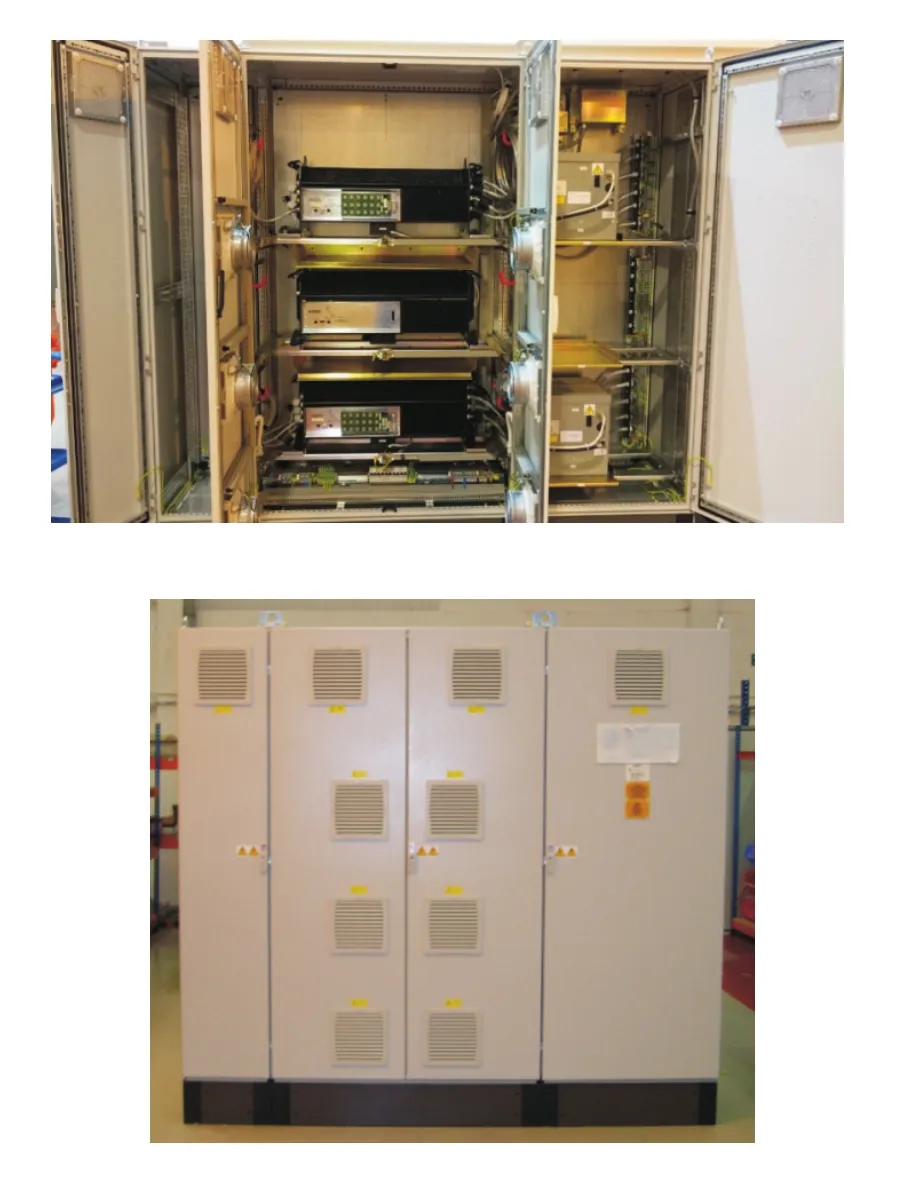
Fig.4 AMB enclosure with three AMB controllers,two active and one spare

Fig.5 Hermetically sealed AMB motor-compressor

Fig.6 Canned AMB for sealed MC
2 Design Considerations for Integrated Motor-compressors
A schematic of a typical hermetically sealed motor-compressor configuration with a single shaft is shown in Figure 7(Al-Aidarous&Shultz,2014).There are two radial bearings and one axial bearing for the whole machine,and the shaft seals have been eliminated.
Because the machine casing inherently creates a seal,gas leakages to the external environment are eliminated and no dry gas seals are required between the impellers and the AMB hardware.This has a positive effect on the reliability and availability of the machine.The elimination of dry gas seals also reduces the bearing span,making it possible to increase the speed of the machine or the number of impellers to achieve a higher power density and higher efficiency for the motor-compressor.
Such performance improvements,however,are normally associated with a higher complexity of motor-compressor and AMB system design,at both the machine or system level.At the machine level,complexity is determined by the exposure of the AMB stator and rotor parts to the pressurized gas environment.Exposure increases windage losses and requires cooling flows to evacuate the heat produced in the AMB cavities.The compatibility of stator and rotor materials with the process gas,throughout the entire operating life of the machine,must also be evaluated.At the system level,complexity is determined by the integration of the secondary cooling flows of the two machines and their effect on the axial loads of the machine.When the motor and compressor are on the same shaft,or rigidly coupled shafts,rotordynamic challenges also increase.
Materials used for the mechanical and electrical AMB components inside the machine and in contact with the gas are typically compatible with clean gas mixtures of hydrocarbons,free of acidic components,chlorides and contaminants.If the gas is a clean mixture of hydrocarbons,standard,open AMB design construction can be used,with AMB stator and sensor parts directly exposed to the process gas.
When the process gas is sour or contains chlorides or contaminants not compatible with standard mechanical and electrical hardware materials,a canned AMB solution is preferable.In a canned AMB,a thin metallic lining,compatible with the process gas,separates and protects the sensitive AMB stator parts from the process gas aggression(Figure 8).The canning completely protects the bearing electrical windings,conductors,and wiring splices from contamination from the H2S and other liquid contaminants.In applications with sour or acid gas with possible liquid water content,corrosion resistant materials,as dictated by NACE MR0175/ISO15156Standards,are normally used for rotor laminations subject to high stresses during assembly and operation.

Fig.7 Hermetically sealed AMB motor-compressor.(Al-Aidarous&Shultz,2014)[7]

Fig.8 Canned AMB
In addition,motor-compressors pumping corrosive and contaminated gas will benefit from corrosion resistant and fouling resistant auxiliary bearing systems.All materials in the auxiliary bearings must be corrosion resistant.For resistance to particulate fouling,such as sand ingress,a bushing type auxiliary bearings with no rolling elements may be adopted(Figure 9),as rolling elements may seize when particulate fouling is present.
At the machine level,canned AMBs docreate some integration challenges.First,the canned AMB construction and the materials compatible with the sour gas entail a degradation of the static and dynamic load performances of the bearings.This normally requires larger bearing sizes and a longer bearing span to compensate for the reduced magnetic flux densities,resulting in more challenging rotordynamics design,especially on flexible rotors.

Fig.9 Bushing-type corrosion-resistant auxiliary bearings
Limitations on allowable stresses of the AMB rotor components(i.e.,the rotor laminations and thrust collar)set limits on the rotating speed of the machine or require special design of the components to reduce the level of stresses to within acceptable limits.For the reasons stated above,when corrosion resistant materials are used for the AMB rotor parts,a vertical rotor machines provide some advantages compared to horizontal axis machines,because the static radial loads due to the rotor weight are eliminated and the overall diameter and axial length of the bearings can be reduced.
Further complexities involve the cable routing and interfaces with the external connectors of the machine.
For this reason,while canned AMBs have been qualified and in continuous operation for more than 10 years,they represent the summit of complexity for AMB motor-compressor applications.Use of this design should be carefully considered and balanced against alternative solutions.
3 VCL Integrated AMB Motor-compressor
A new family of high-power hermetically sealed motor-compressors,the Vessel Compressor Line(VCL),is now in development for pipeline compressor applications in oil&gas(Figure 10).

Fig.10 VCL integrated motor-compressor
3.1 Machine Design
The VCL unit comprises a compressor and a high-speed electric motor,each equipped with an AMB system and cooling system.The motor shaft and the compressor shaft is connected by a flexible coupling.A typical single-layer configuration for pipeline compressors,where the pressurized casings are assembled to the base to form a single skid,has been adopted.
The compressor is designed as a cylinder structure with vertical split designs at each end.The compressor casing is connected to the pressurized casing of the motor at the drive end by a flange,fastened by bolts and positioned by rabbets,to form an integrated pressurized casing.At the non-drive end,the flange and the casing body are installed with a clasp ring,which can effectively reduce the weight of the machine unit and save on material costs.
The sealed cooling systems are arranged inside the skid.The cooling gas is extracted from the outlet of the first stage impeller of the compressor,which,by filtration,provides the cooling to the stators and rotors of the magnetic bearing systems and to the high-speed motor to ensure the normal operation of the machine unit.
The compressor adopts upper inlet and upper outlet design configuration,where the inlet flange and the outlet flange of the compressor are directly arranged on the top of the pressurized casing.
In the structural design of the machine unit,CFD analysis on the inlet volute and outlet volute is conducted to ensure even distributions of gas flows in inlet and outlet flow channels for improved efficiency of the unit.The calculations and analysis on the strength of the impellers,rotor unbalance response,stability of the centrifugal compressor rotor-bearing-seal system,and torsional vibrations of the motor-compressor train are performed with advanced software to ensure the stable and reliable operation of the machine unit.
Figure 11 shows a schematic of the VCL compressor and AMB design.The compressor comprises the stator(pressurized casing,inner casing,diaphragms,seals,balance drum seal,end flanges,etc.),rotor(main shaft,impellers,spacer sleeves,balance drum,rotor sleeves,half coupling,etc.),and magnetic bearing system.The compressor AMB hardware consists of two radial AMBs,one axial AMB,one radial/axial auxiliary bearing,and one radial auxiliary bearing,all with the requisite position sensors,temperature sensors,and speed sensors.The motor AMB hardware has the same components except for the axial AMB.The compressor’s axial magnetic bearing is a double acting type thrust bearing located at non-drive end of the compressor.
The main mechanical sub-assemblies of the bearing systems are the actuator stator assemblies and the rotor assemblies located at the drive end and the non-drive end of the compressor and the motor.The mechanical system also includes the auxiliary bearing system that supports the rotors during standstill condition or during a rotor landing event.

Fig.11 VCL compressor and AMB design
3.2 AMB Solutions
Given the size and design pressure of the machine,the following key technical issues will be addressed in the application of the magnetic bearings:
Due to the larger component and surfaces,small differences between actual and predicted internal pressures may result in high static and dynamic loads.Therefore,the internal flows and pressure distribution for the integrated machines must be properly evaluated for different operating points,and sensitivity analysis must be conducted.Adequate safety margins must be guaranteed by the thrust bearings.Alternatively,the customer can adopt an automatic thrust balancing system for the machine by controlling the pressure drop across the balance line with a valve.
When a flexible coupling between the motor and compressor is present,the coupling will be immersed in the high-pressure process gas.The coupling must be designed to reduce windage and turbulence losses.High turbulence from the coupling can result in high excitation of the rotor and impact on the dynamic performances of the machine.Coupling designs other than disc and diaphragm type may be considered for this purpose.
To reduce the windage losses,the magnetic bearing and auxiliary bearing air gaps are to be increased 10%to 20%compared to the AMB operating at ambient pressure.Secondary cooling flow distributions must be evaluated for different operating conditions to guarantee that enough cooling flow is provided to the AMB cavities.
Experience on large compressors operating at high pressure and compression ratios has shown that uneven pressure distribution at the inlet volute and scroll of the compressor can generate high static radial loads.Such loads can be comparable to or higher than rotor weight loads and must be properly estimated by the compressor vendor(possibly by means of CFD analysis)for normal operating and off-design conditions.
High shaft power increases the rotor mass and applied forces,requiring larger active magnetic bearings and auxiliary bearings to manage the large static and dynamic loads.The radial and axial dynamic load capacity of the magnetic bearings is dependent on the amplifier power rating.If high dynamic loads are predicted,an AMB controller with a power rating up to 600V/60A(Figure 12)can be selected.

Fig.12 AMB controllers for motor-compressors
EEx-d penetrators for AMBs are available for the integrated motor-compressor.This solution is generally more expensive than the EEx-p solution typically adopted for standalone machines with AMBs operating at quasi-ambient pressure.Alternative penetrators and protection schemes,suitable for operation in the hazardous area identified for the machine,can be applied but must be weighed against other factors,including price,delivery time,and certification requirements.
High performance hybrid auxiliary bearings solution,rotor mounted,are typically not suitable for high-pressure gas applications such as hermetically sealed motor-compressors,due to associated windage losses and dragging torques on the rolling bearings.For this reason stator mounted rolling bearings or bushing type auxiliary bearings are normally used.
Testing of the motor and compressor as standalone units may require special equipment and consideration of the mechanical interfaces,cooling system and rotordynamics.Conversely on standalone motor and compressor the two machines can be tested independently in a configuration more closely representative of the final assembled condition.
Due to the radial clearances required in the auxiliary bearing system,conventional seals in the compressor require larger than normal clearances.The increased clearances can lead to decreased compressor efficiency.As an optional solution,brush seal technology may be integrated with the compressor design.Using brush seals throughout the compressor can increase compressor efficiency by 2 to 3 points,due to the tighter clearances and decreased leakage.
4 Conclusions
Different configurations for motor-compressors equipped with AMB systems,from standalone to hermetically sealed machines,have found their applications in industry.Each configuration involves a different level of integration of the two machines and entails increasing system complexity and design challenges.Starting with standalone centrifugal compressor supported by an AMB system as the least complex configuration,the level of complexity of AMB motor-compressors is increased when AMB controllers are housed in a single enclosure and some auxiliary systems,such as the UPS and transformers,are shared by the AMB controllers for two machines.The level of complexity is further increased when the AMB controls of the two machines are integrated into a single AMB controller.At last,the hermetically sealed motor-compressors equipped with canned AMB in applications with sour or acid gas or with possible liquid water content,corrosion resistant materials,represent the summit of complexity for AMB motor-compressor applications
The optimized design of the machine configuration,structure,cooling system,and magnetic bearing systems,has been conducted in the design framework and overall technical considerations driving the development of a new family of hermetically sealed motor-compressors,VCL integrated motor-compressors,to achieve high compressor performance and efficiency.The special attentions to AMB systems shall be paid in such high power motor-compressor units as addressed in detail in the paper in terms of magnetic bearing design,auxiliary bearing design,controllers,couplings,penetrators and seals.
