Numerical Investigation of Internal Flow in Cavitation Resistant Centrifugal Pump*
2020-01-18DazhuanWuLinlinCaoPengWu
Da-zhuan Wu,2 Lin-lin CaoPeng Wu
(1.College of Energy Engineering,Zhejiang University,Hangzhou,China,2.The State Key Laboratory of Fluid Power Transmission and Control,Zhejiang University,Hangzhou,China)
Abstract:This paper presents numerical research on the cavitation resistive property and hydraulic performance of centrifugal pumps with different meridian plane profile,designed with same import and export dimensions.All the three impellers adopt distinct anti-cavitation design philosophy,which leads to their distinguished appearance feature from ordinary centrifugal impeller.One of them has a hump-type curve in cross section area where the maximum value lies on the position of leading edge of blades.The other one is a inducer-and-impeller-combined type with split blades.For the third impeller,it integrates the main feature of the first two impellers.
Keywords:Centrifugal Pump,Cavitation-resistence Design,Two-pahse Simulation,Local Euler Head
Nomenclature
ρmDensity of Mixture
μmViscosity of Mixture
αkVolume Fraction of Phasek
RBBubble Radius
αnucNucleation Site Volume Fraction
FvapEvaporation Coefficient
FcondCondensation Coefficient
LEH Local Euler Head
LE Leading Edge
TE Trailing Edge
p1static pressure at inlet
p2static pressure at outlet
R1inlet radius
R2outlet radius
A2outlet cross section area
Mntorque
vm1meridional component of absolute velocity
w1relative velocity
u1circumferential velocity
0 Introduction
In pump operation,when the absolute pressure of pumping liquid decline below the local vapor pressure in some portion of flow passage(usually somewhere on suction side behind the leading edge),the liquid will vaporize and aggregate into bubbles causing damage from impact corrosion,cavitation noise and vibration.The more striking feature,energy transfer in impeller is obstructed and destroyed by the cavitation formation and rupture,which forms a head drop in external characteristic.NPSH criterion has been widely accepted in industrial use that NPSH of a particular pump is corresponding to the parameter in head-drop-curve determined by the cavitation experiment.A large number of scholars and institute have engaged in this research area.Pfleiderer Institute conducted experimental investigation of centrifu-gal pump of low specific speed and observed the phemomenon of rotating cavitation[1].In another literature,the internal flow under cavitation condition in a high-speed centrifugal pump with a inducer was numerically simulated and the evolution of bubble was observed through experimental tests[2].
Condensate pump is used to draw water from high vacuum condenser in which the absolute pressure of medium is equal to the vapor pressure at a temperature from 20℃to 35℃.Therefore,the cavitation characteristics and its related impact should be considered within special intention in the design and application.For the constant enhanced attachment to research on anti-cavitation of rotating machinery,several suggestions have been proposed to improve anti-cavitation performance for centrifugal impeller.Thai et al.(2010)[3]conducted parameter optimization research on anti-cavitation performance of centrifugal pump,proposing the optimum configuration for split blades in reducing cavitation size and contributing to the flow stability.In 2015,Song et al.[4]modified blades profile for cavitation with logarithmic spiral and replaced suction side by comnination of tangent line and circle arc line.The result showed improvement in both the cavitation performance and hydraulic effciency.In addition to the improvement for impeller internal flow channel,equipping inducer in front of the main centrifugal impeller is an effective method to suppress cavitation[5].Lee et al.[6]presented experiments to describe the flow instabilities caused by cavitation phenomenon in a two-blade inducer through.By observation of the cavitation surge and measurement of inlet pressure fluctuation,they revealed the relationship between cavitation allowance,flow coefficient and flow stability.Guo et al.[7]compared the influence from different type inducer on the cavitation performance and external characteristics of high speed centrifugal pump.And the optimal selection of inducer type was proposed for the optimization of overall performance.Inducer,with the geometry characteristics as a typical axial impeller,is more inclined to drive bubble clusters outward to the periphery and condense as the pressure rise,avoiding the blockage of entire flow passageway.Therefore,it can still function in a condition with certain degree of cavitation with no serious effect on hydraulic performance.While for most high cavitation resistant inducer,tip leakage and unreasonable match with main impeller induce the inevitable energy loss.
In conventional sense,the first-stage impeller of multistage condensate pump mostly take the measures such as broadening out the entrance,extending the leading edge forward,adopting backward swept blades and et.al.to improve anti-cavitation performance.Recent year,a type of integrated pump with the combination of inducer and centrifugal impeller has been developed and successfully applied to a model aero engine.This impeller has spiral main blades with wrap angle over 360 degrees between which medium and short split blades are arranged.This is more conducive to control flow regime,and reduce energy expension in the aspect of making impeller dimension smaller than tranditional assenmbly structrure.Due to the special integrated formation,this pump has high cavitation resistance under various working conditions and can product steady outlet pressure[8-9].
This paper analyzed and studied the effect of some anti-cavitation design measure mentioned above.Not only the external characteristics was obtained through CFD method,the internal flow state were investigated from different perspective such as span-wise local Euler head,two phase distribution and blade loading.
1 Model structure and dimensions
1.1 Outline and description
Figure 1.illustrates the three centrifugal impeller model under attention in this paper.The meridional profiles are extracted in red lines and the maximum curvature is also labeled in black here.The three of all are double shrouded impeller without leakage flow throughout the tip.While in Figure 1.the shrouds are concealed completely or partly to uncover the internal structure of flow channel explicitly.

Fig.1 Impeller model with different structure

Tab.1 Major parameters of impellers
The impeller#1 is a prototype model that was merely designed with widened passageway at the leading edge(LE)of blade.The blades in impeller#2 are a combination of spi-ral main blades and short split blades,while the meridional contour is analogous to ordinary centrifugal impeller.The two featuresb impeller#1 and#2 are integrated together in#3 model.As table.1 revealed,impeller#2 and#3 share the same geometry parameters and blade placement property.But due to the different meridion curve,the vane size and blade angle distribution(especially in hub)show significant distinction for them.All the three types of impeller exhibt as backward swept blades by the mean of taking different wrap angles for shroud and hub.This design measurement,with common application in stirring paddles and axial fans[10-11],enables the liquid on hub side under the effect of blades earlier than that on the shroud side.Consquently,the local pressure on the shroud side of leading edge show great increment.This is apparent for the suction face where cavitation inception would preferentially occur.In this study,#1 is a kind of odinary impeller and so sweep back angle is 20 degree,while for impeller#2 and#3,they have a sweep back angle of 90°on the reference of general inducer.
1.2 Meridional plane and blade angle
As mentioned in the outline,diverse meridional contour including blade distribution have been employed in these three impellers.The horizontal axis of Figure 2 illustrates the location in meridional plane along the direction of main stream-wise in normalized fraction,where 0 represents the entrance of impeller and 1 indicates the outlet.The vertical coordinate shows the value of quasi-orthogonal cross-sectional area.From the area curves with and without blades shown in Figure 2,the placement of blades and impact of blades thickness can be elaborated quantitatively.
For impeller#1 and#3,they share the same cross-sectional area curve without blades,as indicated in blade line,and it reach the maximum close to the twice of entrance area at a position of 0.66,as a result of outer convex hub curve.Relatively,the area curve for impeller#2 manifests a rising trend more gently.
However,due to the blocking effect of two spiral blades with a type of cutting of leading edge,the area curve with blades decline in 5 000mm2at the location of 0.03 of the whole meridional plane approximately.While impeller#1 is an ordinary impeller with six main blades,thereby the drop point located at position of 0.55 and the curve has a larger reduction.
An identical blade angle distribution along normalized blade main stream length has been applied to the blade design of these impellers,as shown in Figure 3.The meaning of horizontal axis in Figure 3 discriminates from the one of Figure 2 in that 0 symbolizes the leading edge(LE)of blade and the trailing edge(TE)is denoted as 1.The five curves represent blade angles relative to tangential at each span-wise location from hub and shroud(from span 0 to span 1).According to Figure 3,the fore-loading mode of blade is employed for the span-wise position approach to hub,while aft-loading mode with small inlet angle is employed for the span-wise position near shroud.This blade-placement method is more benefcial to reduce blade load in shroud side for the inhibition of cavitation,which is generally introduced to high cavitation resistance impeller.
2 CFD Method
2.1 Computational domain and mesh
The computational domain of the centrifugal pump is comprised of impeller,volute,suction tube and discharge tube as revealed in Figure 5.Considering the requirment for reducing the grid quantity and improving the stability of calculation in two-phase solving,structural hex mesh was applied to discretize the computational domain.Due to the complexity of the geometry(especially for impeller#1 and#3 with split blades),the mesh was generated in the pre-processing tool ICEM using blocking segmentation techonology.In this fuction,the topological blocks are established to associate with geometrical element,for instance,vertices to points,egdes to curves,faces to surfaces and et al.By adjusting the number of nodes and their distributive law,it enables to control the total amount of grids and achieve the local refinement for significant location.The topological division for single passage of impeller#3 and volute is shown in Figure 4.

Fig.2 Meridional area for different impeller
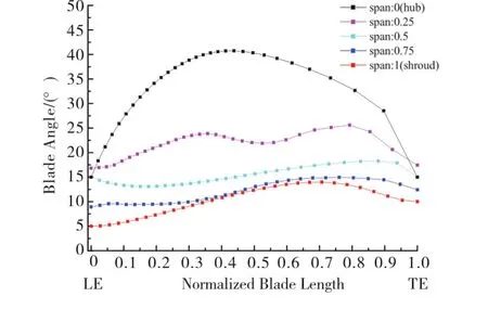
Fig.3 Blade angle distribution

Fig.4 Topological structure for mesh
The mesh is refined near the leading edge,junction thread between balde and covering plate,the cut-water of volute in order to capture phenomenon of cavitation and boundary layer flow,as shown in the right of Figure 5.The grid independence test was conducted in impeller#1 at design flow rate,taking the head and efficiency as the target parameters to evaluate.

Fig.5 Computational domain and meshes of impeller and volute
2.2 Solution algorithm and boundary condition
The impressible three-dimensional continuity and RANS equations closed in Realizable k-e turbulence model are solved by finite volume method using commercial CFD code ANSYS Fluent 17.0.Standard wall function is adopted to solve the near-wall treatment.For solution method of pressure-velocity coupling,SIMPLEC scheme is applied.The pressure field is discretized in PRESTO!model and QUICK model is used for the discretization of the convection terms in the momentum,trubulent kinetic energy,and turbulent dissipation rate equation in cavitation simulation.
The rotational motion in impeller zone is defined using multi-reference frame model and fluid zones are connected by interface pairs.Uniform flow velocity is specified at inlet and constant static pressure is given at outlet.In order to obtain cavitation characteristics curves,vacuum process is simulated by dropping outlet pressure from normal condtion to low pressure in steps.The solid surfaces are set as hydraulically smooth and with no-split walls.
2.3 Multiphase flow model
During cavitation simulation,the mixture model is adopted with the assumption that the mixture of water and gas was regarded as homogeneous multiphase flow.The mixture model is a simplified multiphase model that can modelnphases by solving the momentum,continuity,and energy equations for mixture,the volume fraction equations for the secondary,which has plenty of typical application in several cases[12].In this study,the split velocity and inter-phase drag force are ignored.The main equations are presented below.
The continuity equation for mixture

The momentum equation for mixture


As for mass transfer model in rotation cavitation,Zwart-Gerber-Belamri model is applied in this problem taking the solution robustness and convergence rate into consideration.This model was proposed that the total interphase mass transfer rate per unit volume is calculated using the constant bubble density number and the mass change rate of a single bubble[13].The equation for this cavitation model is as follow

3 Result and Discussions
3.1 Hydraulic performance and cavitation characteristic
In this paper,the hydraulic performance and cavitation characteristic of the pump are converted into non-dimensional parameters,i.e.flow coefficientφ,head coefficientψ,efficiencyη,cavitation numberσ,which is defined as follows:

Figure 6 and 7,respectively show head coefficient and hydraulic efficient curves of the three impeller under different flowrate coefficient.Despite the same main dimension and similar blade angle distribution,the external characteristics curves of this three impellers obtained through simulation bring out some distinctions.Due to the existence of screw-type blades with large wrap angle,the latter two impellers can produce higher head of delivery,especially low flowrate region.Among them,the head-capacity curves of impeller#3 presents an unstable saddle shape where the turning point occures at 0.8 designed flowrate.This is more likely to happen in axial-flow or diagonal-flow pump.With the broadened meridional passage,the effective working area of blades in impller#3 is greater,producing a higher head in full-range scale of flowrate,relative to impller#2.While for impller#1,the changes in head coefficient is more gentle than the other two impllers,and the head of delivery generated by it is superior to that by impller#2 in large flow area.
In impller#1,the meridian passage width is enlarged to reduce absolute velocity and relative velocity according to the velocity triangle shown in Figure 8,making less impact loss and pressure drop of detour flow at leading edge of blades.The meridional area expands intensely and results in chaos of flow field such as secondary flows and reflux vortices,hence the hydraulic efficient of impeller#1 is significantly lower than other two impellers.The inducer-and-impeller conbined pump can be regraded as a concatenated two-stage pump without assembling gaps,which means the eliminateion of counter flow between stages.Meanwhile,the long blades act on fluid sequentially and are more conducive to flow controlling.What is noticeable is that the best efficiency point of impeller#2 and#3 both locates at designed flowrate,and is identical in value.On the other side,the high efficiency area of impeller#3 is situated in large flow region while that of impeller#2 is located in low flow region.Considering the same dimension and identical blade arrangement for this two impllers,it can be conclued from this contrast that the variation of meridian surface only affect on the distribution of high efficient area,yet exerts less influence on the best efficient point.

Fig.6 Comparison of calculated head-flowrate curves

Fig.7 Comparison of calculated efficient curves

Fig.8 Velocity triangle at the impeller inlet
Figure 9 illustrates the head-drop curves in cavitation condition for these three specially designed impellers of high cavitation-resistence performance.All the three curves present a rapid decline below cavitation number of 0.1.Among them,the head of#1 impeller has increased significantly before decline as a common phenomenon happened in centrifugal pumps.While the head of#2 and#3 impeller keep stable within a large range of cavitation number before first critical cavitation point which is usually defined as the point where head begin to change in cavitation characteristic curve[14].As for the conventional critical cavitation number(σa)marking 3%drop of head,#3 impeller is very close to#1 impeller,reflecting that a long and short combined type of impeller based on the original meridional passage makes a limited effect on improving cavitation performance.In general,a broader blade channel would relieve flow channel obstruction by gas clusters and smooth the head-drop curves in transition section.However,the simulation results here possess no consistence with general knowledge,and even a impeller with less variation in meridional area has beter anti-cavitation performance using spiral-type long blades.The internal mechanism will be demonstrated and analysed in the following paragraphs.

Fig.9 Comparison of head-drop curves in cavitating condition
3.2 Span-wise local euler head
In the previous studies on centrifugal pump and axial-flow fan,analysis based on LEH(Local Euler Head)distribution has become a effective approach to understand flow regime in turbomachinery[15-17].In theory,there are a variety of LEH defined with different weighted method to reveal the flow distribution pattern on different dimensions.In the problem of cavitation in centrifugal pump,the regulaities of energy growth and velocity distribution at forepart of impeller channel and area around leading edge plays a most decisive role and is worthy conducting detailed research.In this part,spanwise LEH distribution is introduced as shown in Eq.10 and obtained at the blade LE and TE in Figure 10.
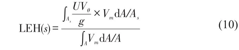

Fig.10 Local Euler head distribution at blade LE and TE
The abscissa is the normalized span-wise location from hub(0)and shroud(1),and the ordinate is the span-wise LEH value define as local Euler head with meridional velocity weighted method at specific span-wise ring surface on LE and TE extension.The gap values between LE and TE represent the contribution to Euler work from each span-wise stream surface.From Figure 10,the LEH of the impeller with spiral long blades are both equal to zero,except the span-wise location near shroud.It is mainly due to the slight circulation reflux near shroud side of LE,making local circumferential opponent of absolute velocity opposite to circumferential velocity.This backflow phenomenon is even more remarkable in impeller#1 due to the dramatically expanded flow passage at LE.Without the fluid controlling effect by long blades,the enlargement in flowing area and high angle of attack angle at shroud side of LE results in stronger inverse pressure gradient along the stream-wise direction.Hence the reflux area is larger and LEH at LE fluctuates more intensely in impeller#1 than other models.As for TE,the LEH distribution shows completely different pattern for these three models.For impeller#2,in the main flow region from 0.4 spans to 0.96 spans,the LEH at TE changes gently and distributes more regularly.The LEH from LE to TE in impeller#2 increases with preferable uniformity along the direction of span wise,especially in main flow region.Whereas for#1 and#3,it has an overall trend in which LEH at TE decline from hub(0)to shroud(1)and rise again after the fall at the span wise that pass through the center of recirculation zone(equivalent to the point where LEH at LE starts to decrease in Figure 10).It is noticeable from the gap value between LE and TE that the energy growth in impeller#1 is dumbbell-shaped which means the work acted by impeller is mainly concentrated on the plate side,meanwhile there is a low energy region where vortex and reflux assembles in central section of flow passage.It is also obvious that the energy growth at shroud side is larger than that at hub side in impeller#3 due to the difference of blade length.
In the respect of cavitation,it generally emerges first at the position behind LE of blade suction surface near shroud side,where there is maximum circumferential velocity and large attack angle.From hydrodynamic characteristic of airfoil,large attack angle strengthens the detour flow around leading edge and magnifies the negative pressure value on suction surface.The LEH distribution at LE in Figure 11 can show the direction and relative magnitude of circumferential velocity opponent for the three impellers.Considering the regularity in velocity triangle at the impeller inlet,the attack angle primarily depends on the vector difference between circumferential velocity and circumferential component of absolute velocity.Hence it can be inferred that cavitation inception will be born in impeller#1 at a larger cavitation coefficient than other models.

Fig.11 Isovolume(vapor fraction above 0.1)and pressure distribution on the impeller under different cavitation coefficients
3.3 Two phase distribution
From the vapor iso-volume and pressure field displayed in Figure 11,the multiphase simulation verifies the conclusion described in the previous section.Cavitation inception happens at 0.52 cavitation coefficient in impeller#1.While for other two models with spiral blades,incipient cavitation coefficient(σi)are quite adjacent and much lower than that of the former one.On the other side,it is a prominent distinction with common designed centrifugal pump that low pressure area lies near hub side in impeller#1 and bubbles first emerge there as well.This can be attributed to the two following two reasons.First,the pressure field in impeller#1 indicates that backward swept blades enable the hub to apply work on fluid before the shroud.In addition,the small curvature of hub profile renders the stream-wise nearby to come out with a sharp turn.As a result,the angle of attack decreases with rapid reduction of the meridional velocity.When it reaches the critical cavitation coefficient(σa)as Figure 11 shown,cavitation area in impeller#1 expand to the center of flow channel and spread downstream further.On the account of identical blade angle distribution and meridian shape at inlet in#2 and#3,the cavitation evolution process show similar pattern in the region between inception cavitation and the point where the external performance start to change.At the initial stage of cavitation development,for example at 0.18 cavitation number in impeller#2 and 0.15 cavitation number in impeller#3,vapor area becomes discontinuous with breakage from LE.The cutting off LE in long blades lead to geometrical discontinuity of suction surface,hence the cavitation area evolves to two parts apparently.As the pressure drops down,cavitation bubble cloud from the two parts blend into an integral whole downstream.In the condition close to cavitation break,region with vapor fraction above 0.1 almost overlay the front part of suction surface.
Figure 12 illustrates the vapor fraction distribution between blade to blade channels on specific span-wise surface.In this perspective,it reveals the influence of vapor area on flow passage under different cavitation conditions more explicitly.The four diagrams for each impeller are obtained at the same cavitation coefficient as Figure 11.Meanwhile,considering the different position of cavitation inception,the blade to blade view for impeller#1 locates at 0.1 span-wise and other two locate at 0.9 span-wise.Figure 12 presents various type of cavity structure.Among them,impeller#2 and#3 have long strip shaped cavitation structure adhere to spiral blades while that in impeller#1 gathers together into block and occupies a large proportion of inter-blade channel as the reduction of cavitation number.Even if the cavitation is fully developed and the external characteristics of pump turn up a significant decline,only half of the flow channel is occupied by vapor area.At the same time the cavitation spread around LE to the pressure surface,instead of expanding into the clump of vapor.In general,the forward extended blades induce the cavitation effect ahead and inducer-typed structure reduces the sensitivity to cavitation for entire impeller.

Fig.12 Vapor volume fraction distribution on blade to blade view under different cavitation coefficients
3.4 Analysis of blade load
More beneficial to employ a central loaded or rear loaded pattern in that an unload blade at front part diminish the differential pressure between two surface,therefore the minimal pressure at suction side drop down.In this study,the inlet blade angles of the three impellers are reduced specially.Figure 13 presents blades load in different span-wise location and the stream-wise location is normalized.Due to the progressively depression of blade angle from hub to shroud,the blade load at inlet ascend from hub to shroud below 0.2 stream-wise location in these three impellers.Impeller#1 is typical middle-loaded pattern where the pressure difference on blade reaches the maximum in the stream-wise range from 0.2 to 0.6,in favor of improving the negative pressure to inhibit cavity growth.According to the comparison of hydraulic and cavitation performance analyzed in the preceding paragraph,the curves of impeller#2 show an ideal blade load distribution in which the majority of work come out from split blades and the front part of long blades present a slight intermediate-loaded type.The overall loading is in its supreme trough prior to the LE of split blades.In impeller#3,the level of blade load along the whole stream-wise is higher than that of impeller#2,especially in front of split blades.The expanded meridional passage increase the loading applied on the forepart of spiral long blades and meanwhile enlarge low pressure area on suction surface in spite of the identical angle placement with impeller#2.Therefore,the cavitation region in impeller#3 spread to a larger degree and exert the impact on external characteristics more.

Fig.13 Blade load along streamwise
4 Conclusion
In this study,three high cavitation resistance impellers are developed and investigated through CFD analysis.Among them,we compared the effect of two anti-cavitation measures in the design of centrifugal pump.In nearly all the interested flowrate range,the impeller models with spiral long blades achieve both higher head and efficiency.At the same time,this type of impeller performs better in anti-cavitation than special designed impeller with enlarged meridional surface.What’s more,applying these two measures simultaneously in one model doesn’t necessarily mean higher cavitation-resistance.Large variation of meridional surface affects the blade loading near LE and aggravates the tendency of cavitation development.
A span-wise LEH at LE is introduced to reflect energy distribution in the front part of impeller.A smooth LEH curve at LE contributes to a stable flow state at inlet state which facilitate the remission of cavitation development.To take in this sense,the cavitation performance can be predicted from LEH distribution obtained from single-phase simulation if the models share same LE location.The two-phase simulation results reveal that the spiral long blades expand the throat area where cavitation cause the most severely impact.Meanwhile the long blades can also prevent cavity from spread to center of flow channel in blade to blade view,hence the whole impeller still perform well in the condition of intense cavitation.
The blade load distribution suggests a better loading pattern for the inducer and impeller combined pump.The ideal arrangement of blade angle should make the loading concentrate on the split blades primarily,with a central-unloaded long blade to ease the trend of cavitation extension.
