Simulation and heat exchanger network designs for a novel single-column cryogenic air separation process☆
2019-10-17QuancongZhangZuqianWuZhikaiCaoQingyinJiangHuaZhou
Quancong Zhang,Zuqian Wu,Zhikai Cao,Qingyin Jiang,Hua Zhou
Department of Chemical and Biochemical Engineering,National Engineering Laboratory for Green Chemical Productions of Alcohols-Ethers-Esters,College of Chemistry &Chemical Engineering,Xiamen University,Xiamen 361005,China
ABSTRACT To realize the industrialization of the novel single-column air separation process proposed in previous work,steady-state simulation for four different configurations of the single-column process with ternary(nitrogen,oxygen and argon) is developed.Then,exergy analysis of the single-column processes is also carried out and compared with the conventional double-column air separation process at the same capacity.Furthermore,based on the steady-state simulation of single-column processes,the different heat exchanger networks(HENs)for the main heat exchanger and subcooler in each process are designed.To obtain better performance for this novel process,optimization of process configuration and operation is investigated.The optimal condition and configuration for this process is consisted as:feedstock is divided into two streams and the reflux nitrogen is compressed at the approximate temperature of 301 K.In addition,HEN is optimized to minimize the utilities.HENs without utilities are obtained for the four different configurations of single-column process.Furthermore,capital costs of the HEN for different cases are estimated and compared.
Keywords:Cryogenic air separation Single-column Exergy Pinch technology Heat exchange network☆ Supported by the National Natural Science Foundation of China (21576228).
1.Introduction
High purity of oxygen,nitrogen and argon is largely demanded in the petroleum,chemical processes,steel,semiconductor,food processing,and health care industries.Cryogenic distillation,pressure swing adsorption and membrane separation are three commercially available methods for air separation [1-3].However,pressure swing adsorption and membrane separation are typically used to separate only a single component from air,and the product purity is not very high.The cryogenic separation is the dominant technology for producing large quantities of high-purity oxygen,nitrogen,and argon [4].Cryogenic distillation air separation process is usually a double-column separation process,consisting of low and high pressure columns.By combining the condenser of high pressure column with the boiler of low pressure column,the latent heat of air vaporization can be exchanged with the condensation heat of pure nitrogen in the double-column separation process,resulting in reduced energy consumption in air separation unit[5-8].A large pressure difference is required between the high and low pressure columns to make the energy exchange possible.The pressure difference in the double-column air separation unit is satisfied by compression of feeding air.The energy cost of the double-column air separation unit still remains high due to the irreversibility between low and high pressure columns [9,10].
Various studies have been carried out to reduce energy consumption of the cryogenic air separation process.Kansha[11]provides an innovative cryogenic air separation process incorporating heat circulation,energy consumption is reduced by self-heat recuperation,and the process simulation with air that only contain oxygen and nitrogen was studied based on PRO/IITM.A novel structure of a full tower ideal internal thermally coupled air separation column (ITCASC) is proposed by Chang [12].Comparative studies against the conventional cryogenic air separation column show that the proposed ITCASC process has a larger extraction rate and better energy efficiency.Moreover,four typical configurations of the single-column processes are constructed and simulated on the ASPEN PLUS platform in our previous work [13].The research results show that the single-column processes has better exergy efficiency compared with the conventional double-column air separation unit.Furthermore,the heat integration is a strategic target to achieve more efficient in processing industries.The heat exchanger network (HEN) design method is a widely used technology for energy integration in the process industries [14-22],which has already been applied successfully in numerous grass-root and revamp projects for over three decades.However,only oxygen and nitrogen are considered in the feedstock(air) and heat integration is neglected in our previous study.To realize the industrialization of this novel single-column air separation process,oxygen,nitrogen and argon should be considered in the feedstock.In addition,heat integration and capital cost should be investigated in the novel air separation process.So the steady-state simulation of single-column process for the feedstock of ternary (oxygen,nitrogen and argon)is developed.Exergy analysis of single-column processes is also carried out and compared with the conventional double-column process for ternary feedstock.And then,on the basis of steady-state simulation of single-column processes,a detailed heat exchanger network for main heat exchanger and subcooler in each process is designed by pinch technology,and capital costs for different cases are estimated and compared.
2.Process Description
2.1.Industrial double-column air separation process
In order to reveal the advantages and promising application prospect of the novel single-column process,the existing industrial double-column air separation process is also used as a comparison,and the flow-sheet of such processes is briefly described here.A schematic diagram of the double-column cryogenic air separation process is presented in Fig.1.The process involves two distillation columns operating at different pressures.The operational pressure of the lower column (B8 in Fig.1) is higher than that in the upper column(B6 in Fig.1).In the lower column,oxygen-enriched liquid air and liquid nitrogen can be obtained.This liquid nitrogen is used as reflux of the distillation operation.In Fig.1,feed air(stream 1)is compressed via the compressor (B1) and then divided into two streams.Much of the compressed feed stream(stream 4)is cooled using the product streams in a main heat exchanger (B4) and enters the lower column bottom stage slightly above dew-point condition.The remaining of the feed stream (stream 3) is further compressed in a booster air compressor (B3) and then cooled in the main heat exchanger (B4).This stream is expanded in the expander (B5) and injected at an intermediate stage in the upper distillation column (B6) as feedstock of the column.The mechanical energy stream (S1) of expander B5 is used by the compressor(B3).Heat stream (S2) on the top of lower column (B8) is used as reboiling energy at the bottom of upper column (B6).A subcooler heat exchanger(B7)is used to decrease the liquid nitrogen(stream 18) and oxygen-enrich liquid air (stream 15) temperature below their corresponding dew-point before undergoing an adiabatic expansion in downstream valves (B9 and B10),using high-purity nitrogen(stream 8)and waste nitrogen(stream 11).In the distillation column B6,high-purity nitrogen (stream 8),waste nitrogen(stream 11),gaseous high-purity oxygen (stream 21),and liquid high-purity oxygen (stream 23) are obtained,respectively,while in B8 (the lower distillation column),oxygen-enriched liquid air(stream 15) and high-purity nitrogen (stream 18) are obtained.
2.2.A novel single-column air separation process
To reduce such a pressure difference between upper column and lower column,and thus the energy consumption,a novel near atmospheric pressure single-column air separation process implementation of thermal pump technique is proposed in our previous study[13].Different from the previous work,the feedstock of ternary (oxygen,nitrogen and argon) is considered in this work.Compared with the double-column cryogenic air separation process,the novel single-column air separation process includes a nitrogen compressor acting as a thermal pump where nitrogen can be compressed in normal or low temperature.In the proposed cryogenic air separation process,the distillation unit is a single-column,and the reflux of liquid nitrogen is produced by the nitrogen compressor.The distillation column in the single-column process can be run in the atmosphere;therefore,the outlet pressure of the air compressor in single-column process is lower than that in the double-column process.The features of the new process involve:(1) 87 K of feed temperature in the distillation column;(2) part of air used as the reflux;(3) all (or most) of air expanded by the expander.
On the basis of the previous work,four configurations of singlecolumn air separation processes are constructed and shown in Figs.2-5.Some differences of these configurations are described in the following sections.

Fig.1.Flowsheet of cryogenic double-column air separation unit.

Fig.2.Flowsheet of atmosphere single-column air separation unit of Case I.
The process flowsheet of Case I is shown in Fig.2,where the feed air (stream 1) is compressed by two compressors (B2 and B3)as stream 3.Next,this stream is cooled by the lower temperature effluent streams from distillation column section (B1) in the main heat exchanger (B4).After the main heat exchanger,all of the compressed air (stream 5) is expanded in expander B5,and then sent to the single distillation column (B1).The mechanical energy stream (S1) of expander B5 is used by the compressor(B3).Before the main heat exchanger,the reflux nitrogen (stream 10)is compressed in a compressor(B10)at the approximately temperature 301 K.Then the reflux nitrogen is cooled in the main heat exchanger (B4) and liquefied in a cooler (B8).Heat stream (S2)from the cooler (B8) is used as reboiling energy at the bottom of the distillation column(B1).In subcooler B7,heat exchange is carried out between high-purity nitrogen (stream 7),waste nitrogen(low-purity nitrogen,stream 17),and reflux (stream 14) so as to utilize the cold energy of stream 7 and stream 17.Finally,the product is obtained:high-purity gaseous nitrogen (stream 11),waste nitrogen or low-purity nitrogen (stream 19),high-purity gaseous oxygen (stream 22),and high-purity liquid oxygen (stream 20).
The configuration of Case II as shown in Fig.3,different from Case I,is that part of the compressed air is expanded as the feedstock of the distillation column (stream 3),and another part of the compressed air is liquefied as the feedstock of the distillation column(stream 4B).In Case I,all of the compressed air is expanded as the feedstock of the distillation column (stream 3 in Fig.2).
The configuration of Case III as shown in Fig.4,different from Cases I and II,is that the reflux nitrogen(stream 34)is compressed at the approximate temperature of 93 K.In Cases I and II,reflux nitrogen is compressed at the approximate temperature of 301 K(in Figs.2 and 3,both are stream 10).In addition,the difference from Case II is that all of the compressed air (stream 3 in Fig.4)are expanded before the distillation column.
Case IV is shown in Fig.5.The difference from Case I includes:the reflux nitrogen (stream 11 in Fig.5) is compressed at the approximate temperature of 93 K,part of the compressed air(stream 3 in Fig.5) is expanded as the feedstock of the distillation column,and another part of the compressed air (stream 4B in Fig.5) is liquefied as the feedstock of the distillation column.The difference from Case II is that the reflux nitrogen is compressed at the approximate temperature of 93 K.The difference from Case III is that part of the compressed air is liquefied as the feedstock of the distillation column.

Fig.3.Flowsheet of atmosphere single-column air separation unit of Case II.

Fig.4.Flowsheet of atmosphere single-column air separation unit of Case III.
3.Process Simulation
3.1.Operational conditions
The above four single-column processes and the conventional double-column process were simulated in the steady-state simulator,ASPEN PLUS V7.2,using the Peng-Robinson equation of state.In addition,binary interaction parameters for oxygen,nitrogen and argon are improved in ASPEN PLUS according to reference [23].In this simulation,the feed air is 50000 m3·h-1with temperature and pressure at 303 K and 101325 Pa.The desired productivities are high-purity nitrogen(99.9 mol%)and low-purity nitrogen(approximately 95.3 mol%),both at 20000 m3·h-1,while liquid and gaseous oxygen(above 99.5 mol%)at 10000 m3·h-1.The isentropic efficiency of the compressor is set as 0.80 at normal temperature,and 0.85 at low temperature and the efficiency of the expander is set as 0.85.For the double-column process,the isentropic efficiency of the compressor is 0.8 and expander is 0.85.The pressure drop is set as 10 kPa for the main heat exchanger and distillation column.The loss of the cold energy is assumed as 20 kW·h for the distillation column,and 3 kW·h for the liquid nitrogen subcooler,respectively.The minimum temperature difference(ΔT)of heat exchanger is assumed as 2 K in the hot side and 3 K in the cold side.

Fig.5.Flowsheet of atmosphere single-column air separation unit of Case IV.
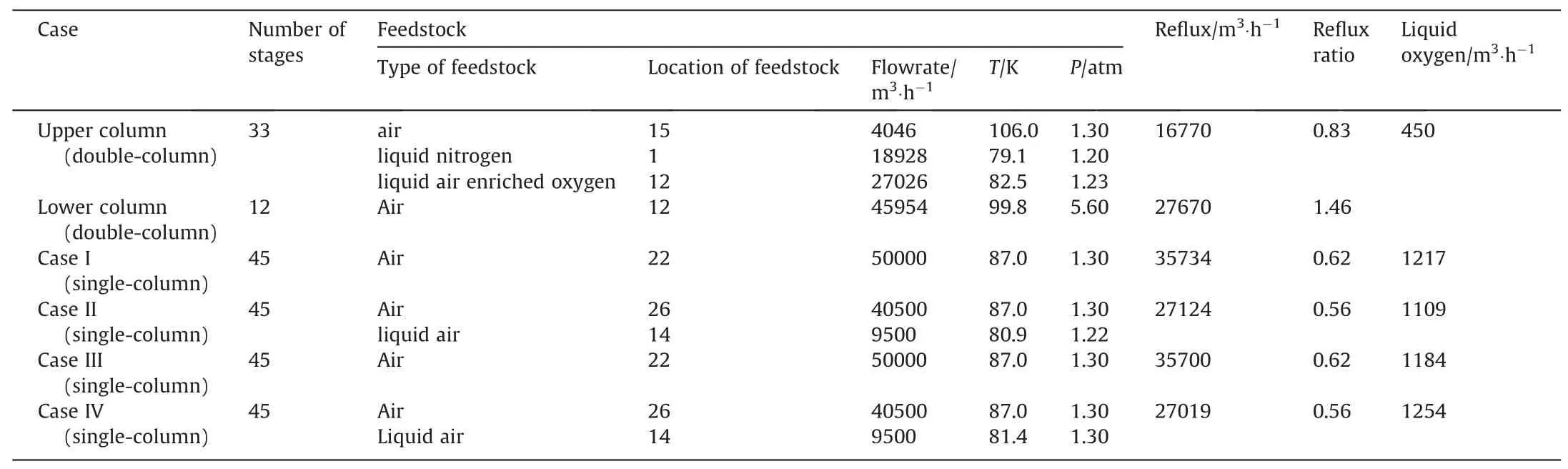
Table 1 Operation conditions for distillation column in different cases (1 atm=101325 Pa).
The conventional double-column usually has 45 trays,thus,the single-column is set as 45 trays.The feed-tray locations are optimized on the basis of oxygen recovery ratio.The distillation column operational parameters of each process are given in Table 1.The feedstock of air consists of oxygen (20.95%),nitrogen(78.118%) and argon (0.932%).Exergy analysis is also carried out on the basis of simulation results.
3.2.Simulation results
In this section,the simulation results of the conventional double-column process and the novel single-column process are provided.Table 1 presents the feed conditions(position,flow rate,temperature,and pressure) and the reflux of the upper column(B6)and lower column(B8)in double-column process.The number of stages for the upper column is 33,while the number of stages for the lower column is 12.The main properties (e.g.,flow rates,temperature,pressure,mole fraction,and enthalpy) of streams for the double-column process are listed in Table 2.
The flowsheet of Case I for the single-column air separation process is presented in Fig.2.In this case,the reflux nitrogen is compressed at a temperature of 301 K.The feed temperature of the distillation column is 87 K.All of the feed air (50000 m3·h-1) is expanded in the expander (B5) before the distillation column,and the work of the expander is provided to the compressor (B3).The feed conditions and reflux ratio of Case I can be found in Table 1.The product quantity of the liquid oxygen is 1217 m3·h-1for this case.The properties of main streams for Case I are shown in Table 3.The operation conditions and simulation results of the other cases are shown in Tables 1,4-6.
4.Design of Heat Exchanger Networks
4.1.Heat exchanger network design method
In the process simulation,heat transfer between multiple hot and cold streams is implemented by the block MHeatX that given in ASPEN PLUS.However,only energy balance between the various streams is considered in the MHeatX block.The detailed network of the heat exchanger is neglected.To consummate the conceptual design of the single-column air separation process,the detailed heat exchanger network for main heat exchanger and subcooler in each single-column process has been developed by pinch technology on ASPEN ENERGY ANALYZER V7.2.The required stream data for heat exchanger network design is obtained from the results of process simulation,as shown in Table 7.
According to basic rules [15],feasibility principles and tick-off heuristic rules[19]in pinch technology,the design of heat exchanger networks can be summarized as five steps [20].
(1) Divide the problem at the pinch into separate problems;
(2) The design for the separate problems is started at the pinch,moving away;

Table 2 Stream properties of the double-column air separation process (1 atm=101325 Pa)

Table 3 Stream properties of the single-column air separation process (Case I) (1 atm=101325 Pa)
(3) Temperature feasibility requires constraints on the CPs to be satisfied for matches between the streams at pinch;
(4) The loads on individual units are determined using the tickoff heuristic to minimize the number of units.
The minimum temperature difference ΔTminbetween the composite curves is assumed as 2 K.The heat transfer coefficient(HTC)value is 0.2 kW·m-2·K-1for the streams.Each stream involved in heat transfer is in the form of single-phase (gas or liquid),and no phase transition occurs in the course of the heat transfer.Heat exchanger network is designed to minimize the utilities as well as the number of exchangers as possible.
4.2.Results of heat exchanger network design
HEN can be easily described by a standard grid diagram.The grid diagram of HEN for main heat exchanger(B4 in Case I)is shown in Fig.6.There are two hot streams and three cold streams in this process.Hot streams are located in the upper side of the grid diagram and cold streams are in the lower side.There are four heat exchanger units in this network and without any cooler or heater.The minimum temperature difference (ΔT) of main heat exchanger (B4 in Case I)in the steady state simulation is setting as 2 K in the hot side and 3 K in the cold side,while the minimal temperature difference ΔTminbetween the composite curves is specified as 2 K.In the pro-cess simulation,energy balance between the various streams is considered in the MHeatX block.As a result,the total heat load of hot streams is just equal to the total heat load of cold streams and no utilities are required.The results of this HEN are provided in Table 8.

Table 4 Stream properties of the single-column air separation process (Case II) (1 atm=101325 Pa)

Table 5 Stream properties of the single-Column air separation process (Case III) (1 atm=101325 Pa).
The grid diagram of HEN for subcooler(B7 in Case I)is shown in Fig.7.There are threshold problems in this HEN.Usually,problems similar to those are treated as one half of a pinched problem.Hence,the design of the HEN is started at the side with smaller temperature difference.The minimum temperature differences(ΔT)of subcooler(B7 in Case I)are higher than 2 K in both hot side and cold side.Just like the reason mentioned above,the total heat load of hot streams is just equal to the total heat load of cold streams,so no utilities are required.There are two cold streams,one hot stream and two heat exchanger units in the HEN.The results of the HEN are presented in Table 8.
The grid diagrams of HEN for main heat exchanger and subcooler in other cases are shown in Figs.8-13,and the results of total cost,heat exchange area,the number of heat exchanger unit,etc.are given in Table 8.
5.Analysis and Discussion
5.1.Exergy analysis
As in our previous study,exergy analysis for double-column process and single-column process (different configurations) areprovided,where the theory of exergy analysis used in this work is based on the literature [4].Exergy efficiency is expressed as the ratio of the output exergy of the process or devices to the input exergy of the process or devices:

Table 6 Stream properties of the single-column air separation process (Case IV) (1 atm=101325 Pa)

Table 7 Stream data of main heat exchanger (B4) and subcooler (B7) in different cases

Table 8 Results for heat exchanger network of main heat exchanger(B4)and subcooler(B7)in different cases (capital cost index=capital cost of an HEN).

where,E indicates the exergy of streams;W indicates the work.The main modules of air separation unit(ASU)consist of air compressor(AP),associate air compressor (AAP,only in Case II),main heat exchanger (MHX),distillation system (DS,includes distillation column and subcooler),and nitrogen compressor (NP).All of the exergy analysis results of the proposed process and conventional process are listed in Table 9.
It can be obtained from Table 9 that the exergy efficiencies of Cases I and II are higher than the exergy efficiency of conventional double column process in our simulation,while the exergy efficiencies of Cases III and IV are lower than the exergy efficiency of conventional double column process.Compared to the conventional double-column process,an advantage of the proposed single-column process is that the amount of the cold energy is determined by the air pressure in the single-column [13],while the cold energy of the conventional double-column is decided by the amount of expanded air that is limited by the upper column[23].The cold energy of the single-column can be varied by adjusting the air pressure with little influence on distillation column operation,which only leads to increase or reduce the quantity of liquid products.However,it is difficult to adjust the quantity of liquid products in the double column because the amount of expanded air is limited by the upper column.The production of liquid oxygen in this study (Case I—1217 m3·h-1,Case II—1109 m3·h-1,Case III—1184 m3·h-1,and Case IV—1254 m3·h-1) is much lower than that in our previous work (Case I—2083 m3·h-1,Case II—2115 m3·h-1,Case III—2083 m3·h-1,and Case IV—2414 m3·h-1).Thus,the exergy efficiency of the processes is also greatly reduced (the exergy efficiency in previous study:Case I—32.15%,Case II—32.78%,Case III—28.95%,and Case IV—30.41%).Another reason for the reduction of the exergy efficiency is that the introduction of argon which increases the difficulty of air separation.In the proposed single-column process,the exergy efficiency is affected by the quantity of liquid oxygen production.When the liquid oxygen production of the single-column process is higher than a certain value,the exergy efficiency of singlecolumn process will be higher than the exergy efficiency of double-column process at the same processing capacity.The liquid oxygen production of double column in this study (450 m3·h-1) is lower than that in previous study (592 m3·h-1),so the exergy efficiency (21.81%,in this study;26.59%,in previous study) is also lower.

Fig.6.Grid diagram of HEN for main heat exchanger (B4 in Case I).

Fig.7.Grid diagram of HEN for subcooler (B7 in Case I).
Compared to the exergy efficiency of the different configuration single-column processes,the exergy efficiency of the processes(Cases I,II) is higher than the exergy efficiency of the processes(Cases III,IV).The difference of these Cases is that the reflux nitrogen for Cases I &II is compressed at the approximate temperature of 301 K and the reflux nitrogen for Cases III&IV is compressed at the approximate temperature of 93 K.Although the exergy efficiency of NP is higher at the approximate temperature of 93 K,the exergy efficiency of AP is lower.In fact,the exergy efficiency for whole process is affected more by the exergy efficiency of AP.In addition,the exergy efficiency of Case II is higher than the exergy efficiency of Case I.The reason is that the feedstock of Case II is divided into two streams and the feedstock of Case I is kept only one stream.Similar result can be obtained between Case III and Case IV.From the viewpoint of energy saving,the optimal process condition is that the feedstock is divided and the reflux nitrogen is compressed at the approximate temperature of 301 K.
5.2.Heat exchanger network results analysis

Fig.8.Grid diagram of HEN for main heat exchanger (B4 in Case II).

Fig.9.Grid diagram of HEN for subcooler (B7 in Case II).

Fig.10.Grid diagram of HEN for main heat exchanger (B4 in Case III).

Fig.11.Grid diagram of HEN for subcooler (B7 in Case III).

Fig.12.Grid diagram of HEN for main heat exchanger (B4 in Case IV).

Fig.13.Grid diagram of HEN for subcooler (B7 in Case IV).
The objective of the HEN design is to minimize the utilities.If the total heat duty of hot streams is just equal to the total heat duty of cold streams in all designs of the HEN,then no utilities are required.So the operation cost of the HEN is 0.The total cost of a HEN is consisting of the operation cost and the capital cost,thus the total cost is the capital cost only.In these designs of HEN,the default formula (provided by ASPEN ENERGY ANALYZER V7.2)was used as the calculation of the capital cost as following:


Table 9 Comparison of exergy efficiency of different process designs
where,the unit of Capital Cost Index is the cost,the HeatExch Area is heat transfer area,the Shells is number of Shells in an HEN,the default values of the parameters:a is equal to 10000,b is 800,and c is 0.8.
From the results shown in Table 8,the capital costs of the HEN for subcoolers in the four single-column processes are similar,and much less than the capital costs of the HEN for main heat exchangers.Therefore,the capital cost of HEN in the single-column process is mainly decided by the cost of HEN for main heat exchanger.Theresults (capital cost,heat exchange area,the number of heat exchanger unit,etc.) of the HEN for main heat exchanger (B4)and subcooler (B7) in each single-column process are summed and listed in Table 10.The capital cost of HEN in the processes(Cases III,IV)is about half of the total cost of HEN in the processes(Cases I,II).The reason is that the temperature difference is larger in the processes (Cases III,IV).So the driving force of the heat transfer increases and the number of shells and heat transfer area reduces,and then the total cost is saving.

Table 10 Cost summary of heat exchanger network of different process designs
6.Conclusions
Four configurations for single-column thermal pump distillation process with ternary (nitrogen,oxygen and argon) feedstock are investigated and evaluated by different methods.The exergy efficiency of the single-column process is varied with the quantity of liquid oxygen product.When the liquid oxygen production is higher than a critical value,the exergy efficiency of singlecolumn process is higher than the exergy efficiency of doublecolumn process at the same processing capacity.By comparison of different configurations of the single-column processes,the optimal condition and configuration are obtained:feedstock is divided into two streams and the reflux nitrogen is compressed at the approximate temperature of 301 K.Heat exchanger network is designed to minimize the utilities with pinch technology.Minimum temperature difference is setting as 2 K and no utilities are required in all of the HENs.The results of the capital cost of the HEN for different configurations are shown that the minimum cost of the HEN is Case III.
Nomenclature
a,b,c parameters for capital cost calculation of heat exchanger network
CPCheat capacity flowrate of cool stream
CPHheat capacity flowrate of hot stream
Eininlet exergy of a process or devices
Eoutoutlet exergy of a process or devices
NCnumber of cold streams (include their branches)
NHnumber of hot streams (include their branches)
R molar gas constant
Wininlet work of a process or devices
Woutoutlet work of a process or devices
ΔT temperature difference
ΔTminminimum allowed temperature differences
η exergy efficiency
Subscripts
C cold stream
H hot stream
i component i
in inlet
out outlet
0 the environmental conditions
杂志排行

Chinese Journal of Chemical Engineering的其它文章
- Microencapsulated ammonium polyphosphate by polyurethane with segment of dipentaerythritol and its application in flame retardant polypropylene☆
- Distributed control and optimization of process system networks:A review and perspective☆
- Heat exchanger network synthesis integrated with flexibility and controllability☆
- Synthesis of flexible heat exchanger networks:A review☆
- A review of extractive distillation from an azeotropic phenomenon for dynamic control☆
- A review of the current state of biofuels production from lignocellulosic biomass using thermochemical conversion routes