Miniature quad-channel spin-exchange relaxation-free magnetometer for magnetoencephalography∗
2019-04-13JianJunLi李建军PengChengDu杜鹏程JiQingFu伏吉庆XuTongWang王旭桐QingZhou周庆andRuQuanWang王如泉
Jian-Jun Li(李建军),Peng-Cheng Du(杜鹏程),Ji-Qing Fu(伏吉庆),Xu-Tong Wang(王旭桐),Qing Zhou(周庆),and Ru-Quan Wang(王如泉)
1Institute of Physics,Chinese Academy of Sciences,Beijing 100190,China
2School of Physical Sciences,University of Chinese Academy of Sciences,Beijing 100049,China
3National Institute of Metrology,Beijing 100029,China
4School of Physics and Astronomy,Yunnan University,Kunming 650091,China
1.Introduction
Precision measurement of weak magnetic fields has many important applications.[1]Different types of magnetometers,such as the fluxgate magnetometer,optically pumped magnetometer(OPM),and superconducting quantum interference device(SQUID),are widely used in geophysical mineral and oil exploration,[2,3]underwater ordinance detection,[4,5]nuclear magnetic resonance,[6,7]and biomagnetism.[8,9]
Magnetocardiography(MCG)and magnetoencephalography(MEG)are two important biological applications which have attracted significant research and clinical effort in the past two decades.The mainstay technology for MCG and MEG is the low temperature SQUID magnetometer,which can reach a sensitivity of 1 fT/Hz1/2.[10,11]However,it has to be maintained in a liquid helium dewar,which is expensive to manufacture and difficult to service.The dewar also limits the distance between the superconducting quantum interference device(SQUID)sensor and the human brain,which compromises the spatial resolution of the measurement.Moreover,the boiling of liquid helium introduces mechanical noise to the MCG and MEG systems.
The OPM,which uses optical interrogation of the spin of alkali atoms to detect magnetic fields,[12]is another type of ultrahigh sensitive magnetometer,although its sensitivity is limited by spin-exchange collisions. In recent years, a special type of spin-exchange relaxation free(SERF)OPM[13]has been developed,where this limitation is completely eliminated by operating at high density and zero magnetic field.[14,15]Theoretically,its sensitivity limit can be as low as 2 aT/Hz1/2in a 7-cm3cell.[16]The best sensitivity achieved so far is 0.16 fT/Hz1/2,in a gradiometer arrangement,[17]which surpasses that of SQUIDs.Exhibiting many desirable qualities such as low power consumption,low cost,and high reliability,the OPM has the potential to take the place of the SQUID for biological field applications.[18]The OPM system can offer sufficient sensitivity,[13]bandwidth,[19]and spatial resolution[20]for MEG and MCG measurements.[21–23]Even more importantly,the OPM sensor can be placed closer to the human head compared with an SQUID,which can significantly increase the MEG signal strength.
For applications such as MEG and MCG,not only the sensitivity of the sensor,but also the size,weight,power requirements,and spatial resolution are crucial.With a microfabricated vapor cell,a sensitivity of 5 fT/Hz1/2can be reached in a measurement volume of 1 mm3.[24]A low-power,high sensitivity micromachined optical magnetometer, the volume of which is 0.36 cm3,has been demonstrated which runs on 140 mW of heating power and achieves a sensitivity bet-ter than 20 fT/Hz1/2.[25]More recently,atomic magnetometers of various designs have been fabricated,with multiple channels or sensor arrays for measuring the biological magnetic field.[9,26,27]For the detection of fields where the target distance is on the millimeter to centimeter scale,some microfabricated magnetic gradiometers with improved spatial information and common noise cancellation have also been reported.[28,29]High spatial and temporal resolution MEG is a direct means of measuring brain function,and has been applied in epilepsy surgery and pre-operative brain mapping.[30]
In this work,we report a miniature quad-channel SERF magnetometer for MEG measurement.Miniaturization of the sensor is realized by using a single circular-polarized beam.The four channels of the magnetometer share a single beam which is detected by a quadrant photodiode,thus greatly simplifying the gradiometer measurement.The quad-channel sensor operates well as a gradiometer since the common mode noise due to the laser fluctuations is canceled effectively.As part of the design,we have developed a novel current-heating structure which reduces the magnetic field from the heating current at the vapor cell by several orders of magnitude.This type of cluster sensor is extremely suitable for image reconstruction in MEG systems.
2.Experimental setup
Our miniaturized quad-channel OPM operates with a single laser beam for both pumping and probing the atomic polarization.Its high sensitivity results from a combination of an SERF mechanism and zero- field level crossing resonance.The main components of such a sensor head are:an optical section,a potassium vapor cell,a photodetector with a low noise preamplifier,and a heater.Figure 1 shows an actual photo of the sensor,which has dimensions of 190 mm×40 mm×20 mm.All the structural components of the sensor module are fabricated out of polycarbonate plastic using a three-dimensional(3D)printer.

Fig.1.Photo of the magnetometer sensor head.1:Five sets of Helmholtz coils;2:optical section;3:low noise preamplifier;4:heaters covered by Kapton tape;5:optical fiber;6:Farrow cables.
The optical housing is of size 90 mm×20 mm×19 mm,and contains the fiber port,lens,polarizing beam splitter(PBS),reflecting prism,and quarter-wave plate.The optical layout is illustrated in Fig.2.The single laser beam at 770 nm used for the optical pumping is generated by an external cavity diode laser(ECDL,model#ECL801),and is sent to a small nonmagnetic fiber port through a 5-m long polarization maintaining fiber.The output beam is collimated to a diameter of 5.2 mm before passing through a PBS,reflecting prism,and quarter-wave plate.The circularly polarized pump beam is detected after the potassium vapor cell by a four-quadrant photodetector,each element of which has an active area of 4 mm×4 mm.
The atomic polarization is given by Px=2hSxi,deduced from the Bloch equation,[31]where Sxis the electron spin polarization along the laser beam.When a magnetic field modulation of amplitude Bmand frequency wmperpendicular to the laser beam is applied in the dynamic regime,the polarization is given by[32,33]

where,γeis the electron gyromagnetic ratio,q is the nuclear slowing-down factor,J0and J1are Bessel functions of the first kind,Rpis the pumping rate,Rrelis the spin relaxation rate,and B0is the offset field parallel to the modulation field direction.Thus,we can obtain the atomic polarization from the pump beam absorption as a result of the interaction between the light and atomic assemble.

Fig.2. Schematic diagram of the optical paths inside the OPM sensor and the electrical signal connections(heating coils not shown).PM:polarization-maintaining optical fiber;F: fiber port;L:lens;PBS:polarizing beam splitter;P:reflecting prism;Q:quarter-wave plate;C:potassium vapor cell;H:heat insulation;PD:four-quadrant photodiode;TIA:transimpedance amplifier;Gen Out:function generator;DAQ:data acquisition;Lock-in:virtual lock-in amplifier.
The core of the sensor head is the alkali vapor cell containing a small droplet of potassium metal in natural abundance. The cell is made from borosilicate glass,and its outer size is 10 mm×10 mm×10 mm with an interior size of 8 mm×8 mm×8 mm.The center of the cell is 10 mm away from the end of the sensor,and is filled with 750 Torr(1 Torr=1.33322×10²Pa)of nitrogen gas.At high buffer gas pressure,the atoms experience diffusive motion,which increases their time to reach the cell wall.In addition,the nitrogen gas can assist in the pumping process by quenching the excited state.[34]
The vapor cell operates at 160◦C,which corresponds to a potassium density of 1013cm−3.The temperature is maintained through continuous electrical heating,as shown in Fig.3.Four ceramic coated heating coils,each 78-mm long and 4 mm in diameter,have a resistance of 12 kΩ and maximum rating of 20 W.The heating coils are connected in series such that their magnetic fields are opposite in direction.The heat generated is transferred effectively to the vapor cell by a 150-mm long highly efficient heat pipe.The four heaters and heat pipe are housed in an aluminum heatsink.For the cell and heat pipe enclosure,a boron nitride heatsink is used as its Johnson noise is very low,even better than aluminum.At the cell,the magnetic field due to the heaters has decayed by 1/r3to less than 1 nT,where r is the distance from the center of the coils.This remaining field can then be compensated by a set of Helmholtz coils.The entire heating structure and vapor cell are housed in aerogel insulation.
The most important factors of the heater system are how to maintain the required temperature and how to minimize the power consumed,so we first perform a simulation by COMSOL Multiphysics.The experimental results agree well with the simulation.At thermal equilibrium,4.5 W of heater power is required. There is no detectable difference between the magnetic noise levels when the heating is turned on and off.
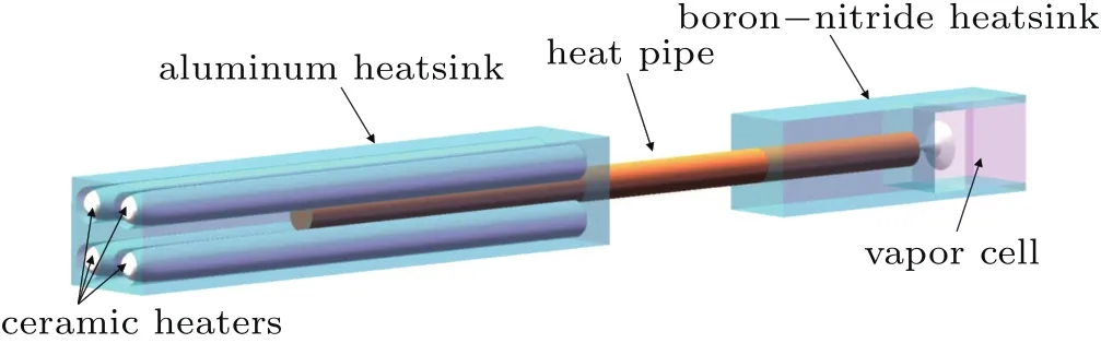
Fig.3.Structure of the heater.
The set of Helmholtz coils includes three pairs of square coils,plus two more pairs to provide a modulation field in the two perpendicular directions of propagation of the pump beam.Both of the two linearly independent components of the magnetic field can be adjusted in each magnetometer channel by simply changing the direction of the modulation.The coils are soldered to the printed circuit board to prevent instability resulting from the long cables.To realize miniaturization and to prevent interference from external electrical noise at the photodiode,the low noise preamplifier is also placed on the circuit board.A 5-m Farrow cable transfers the signals to a virtual lock-in amplifier,and another one provides the compensation and modulation fields.LabVIEW software is used to compose a program to implement the virtual lock-in ampliifer with a 24-bit data acquisition system.
3.Measurement results
The quad-channel sensor is tested inside a five-layer cylindrical magnetic shield made of high-permeability µ-metal,as shown in Fig.4.The geometry of the shield is optimized by both theoretical analysis and finite element numerical simulation.[35]The power and detuning of the pump beam are optimized for the best magnetic sensitivity.The laser power is approximately 0.4 mW per magnetometer channel,and the frequency is detuned by 5 GHz from the D1resonance line of potassium.No active control of the beam power and frequency is implemented in our laboratory environment,although we believe such control would be beneficial for improving the sensitivity of our sensor even further.
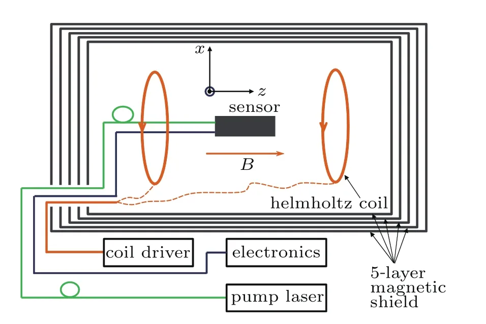
Fig.4.Schematic diagram of magnetic sensitivity measurements.The sensor is placed in the center and parallel to the field of the Helmholtz coil that is wrapped around a slotted cylinder made of teflon.
The background magnetic field at the vapor cell is compensated by three pairs of coils.An external magnetic field provided by a large cylindrical Helmholtz coil is applied perpendicular to the pump beam,and its amplitude is swept from negative to positive.Thus,the transparency of the potassium atomic assemble changes,and its maximum is observed when the magnetic field is extremely close to zero.The full width at half maximum of the zero- field magnetic resonance of channels A to D are 8.45 nT,8.51 nT,8.87 nT,and 11.61 nT,respectively.In Fig.5(a),we only show the channel B,and the others are similar to it.The difference is due to the inhomogeneous light intensity.To obtain the dispersive resonance line shape,a modulated transverse magnetic field with an amplitude of 80 nT and a frequency of 1 kHz is applied.Then the four-quadrant photodiode signal is extracted and demodulated by the virtual lock-in amplifier,by which means the technical 1/f noise in the electronics can be removed.
Magnetic field measurements,which are based on the linear portion of the dispersive resonance line shape,are taken by zeroing the residual magnetic field.Sensitivity is determined by measuring the power spectral density of the magnetometer output and dividing it by the slope of the magnetic resonance.The slopes of the lock-in output signals around zero field value for channels A to D are 2.8 V/nT,2.1 V/nT,3.6 V/nT,and 5.6 V/nT,respectively.Figure 5(b)shows the frequency response of the magnetometer.The data for all channels is taken simultaneously,and we can see that the field sensitivity of the four channels are nearly identical,about 40 fT/Hz1/2over 10 Hz–100 Hz.
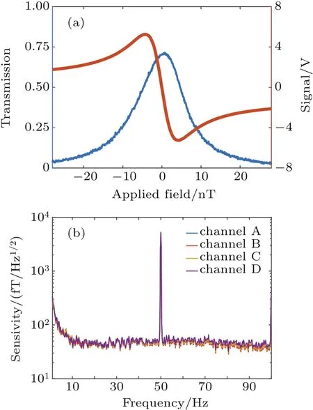
Fig.5.(a)Magnetic resonance of channel B.The blue trace is the transmission of the pump beam through the vapor cell and the red trace is the demodulated output of the virtual lock-in amplifier.(b)Magnetic field sensitivity of the magnetometer.
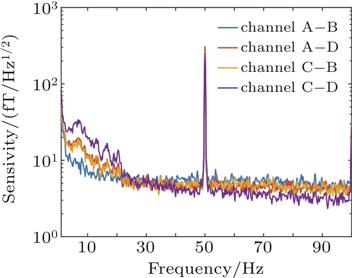
Fig.6.Plot of the gradient field sensitivities of the sensor.For the channel A–B(blue trace),A–D(red trace),and C–B(yellow trace)gradiometers,the inferred single-channel sensitivity is 4 fT/Hz1/2–6 fT/Hz1/2between 30 Hz and 100 Hz,and that of channel C–D(purple trace)is 3.5 fT/Hz1/2over 60 Hz–100 Hz.
The first-order gradiometers,which include two directions,are formed by taking the difference between adjacent magnetometer channels,which cancels the common magnetic field noise.Supposing that the remaining noise is uncorrelated,the noise level is divided by 21/2to obtain the equivalent single-channel magnetometer sensitivity.Figure 6 shows the performance of the four synthetic gradiometers.Their noise levels are less than 6 fT/Hz1/2over 25 Hz–100 Hz,which is a great improvement over the single channel sensitivity of our detector.
4.Conclusion
We have developed a miniature quad-channel OPM with high sensitivity for the detection of biological fields,specifically for MEG.It operates in the SERF regime,requires only a single beam,is compact but can implement multi-channel measurement,and has enough spatial resolution for MEG measurement.A novel current-heating structure based on a heat pipe can eliminate both the magnetic field and noise from the heating coils.We have achieved gradiometric sensitivities better than 6 fT/Hz1/2,which is more than sufficient for the observation of MEG signals.Moreover,the MEG signal of steady-state visual evoked potentials response has been successfully observed from all four channels of this sensor.The compactness of our design will enable multiple sensors to be packed densely around the head in an array.The miniaturization and simultaneous detection of two gradient magnetic fields are most desirable features,and should have important application in the development of MEG worldwide.
[1]Fitzgerald R 2003 Phys.Today 56 21
[2]Foley C P,Tilbrook D L,Leslie K E,Binks R A,Donaldson G B,Du J,Lam S K,Schmidt P W and Clark D A 2001 IEEE Trans.Appl.Supercond.11 1375
[3]Narkhov E D,Sapunov V A,Denisov A U and Savelyev D V 2014 Transactions on Ecology and the Environment,Vol.186(Southampton:WIT Press)p.649
[4]Clem T R 1998 Nav.Eng.J.110 139
[5]Hirota M,Nanaura K,Teranishi Y and Kishigami T 1997 IEEE Trans.Appl.Supercond.7 2327
[6]Savukov I M and Romalis M V 2005 Phys.Rev.Lett.94 123001
[7]Xu S,Yashchuk V V,Donaldson M H,Rochester S M,Budker D and Pines A 2006 Proc.Natl.Acad.Sci.USA 103 12668
[8]Boto E,Meyer S S,Shah V,Alem O,Knappe S,Kruger P,Fromhold T M,Lim M,Glover P M,Morris P G,Bowtell R,Barnes G R and Brookes M J 2017 Neuroimage 149 404
[9]Boto E,Holmes N,Leggett J,Roberts G,Shah V,Meyer S S,Muñoz L D,Mullinger K J,Tierney T M,Bestmann S,Barnes G R,Bowtell R and Brookes M J 2018 Nature 555 657
[10]Sternickel K and Braginski A I 2006 Supercond.Sci.Technol.19 S160
[11]Fagaly R L 2006 Rev.Sci.Instrum.77 101101
[12]Budker D and Kimball D F J 2013 Optical Magnetometry(New York:Cambridge University Press)pp.3–7
[13]Kominis I K,Kornack T W,Allred J C and Romalis M V 2003 Nature 422 596
[14]Happer W and Tang H 1973 Phys.Rev.Lett.31 273
[15]Happer W and Tam A C 1977 Phys.Rev.A 16 1877
[16]Allred J C,Lyman R N,Kornack T W and Romalis M V 2002 Phys.Rev.Lett.89 130801
[17]Dang H B,Maloof A C and Romalis M V 2010 Appl.Phys.Lett.97 151110
[18]Knappe S,Sander T and Trahms L 2014 Magnetoencephalography,2nd Edn.(New York:Springer)pp.993–999
[19]Shah V,Vasilakis G and Romalis MV2010Phys.Rev.Lett.104013601
[20]Acosta V M,Bauch E,Ledbetter M P,Santori C,Fu K M,Barclay P E,Beausoleil R G,Linget H,Roch J F,Treussart F,Chemerisov S,Gawlik W and Budker D 2009 Phys.Rev.B 80 115202
[21]Zetter R, Iivanainen J, Stenroos M and Parkkonen L 2018 Brain Topogr.31 931
[22]Wyllie R,Kauer M,Smetana G S,Wakai R T and Walker T G 2012 Phys.Med.Biol.57 2619
[23]Li R J,Quan W,Fan W F,Xing L,Wang Z,Zhai Y Y and Fang J C 2017 Chin.Phys.B 26 120702
[24]Griffith W C,Knappe S and Kitching J 2010 Opt.Express 18 27167
[25]Mhaskar R,Knappe S and Kitching J 2012 Appl.Phys.Lett.101 241105
[26]Johnson C N,Schwindt P D D and Weisend M 2013 Phys.Med.Biol.58 6065
[27]Alem O,Sander T H,Mhaskar R,LeBlanc J,Eswaran H,Steinhoff U,Okada Y,Kitching J,Trahms L and Knappe S 2015 Phys.Med.Biol.60 4797
[28]Sheng D,Perry A R,Krzyzewski S P,Geller S,Kitching J and Knappe S 2017 Appl.Phys.Lett.110 3
[29]Colombo A P,Carter T R,Borna A,Jau Y Y,Johnson C N,Dagel A L and Schwindt P D 2016 Opt.Express 24 15403
[30]Singh S P 2014 Ann.Indian Acad.Neurol.17 S107
[31]Seltzer S J and Romalis M V 2004 Appl.Phys.Lett.85 4804
[32]Shah V and Romalis M V 2009 Phys.Rev.A 80 013416
[33]Cohen-Tannoudji C,DuPont-Roc J,Haroche S and Lalo¨e F 1970 Rev.Phys.Appl.5 95
[34]Rosenberry M A,Reyes J P,Tupa D and Gay T J 2007 Phys.Rev.A 75 023401
[35]Fu J Q,Du P C,Zhou Q and Wang R Q 2016 Chin.Phys.B 25 010302
猜你喜欢
杂志排行

Chinese Physics B的其它文章
- Entangled multi-knot lattice model of anyon current∗
- Observing the steady-state visual evoked potentials with a compact quad-channel spin exchange relaxation-free magnetometer∗
- Quantum interferometry via a coherent state mixed with a squeezed number state∗
- Cavity enhanced measurement of trap frequency in an optical dipole trap∗
- 7.6-W diode-pumped femtosecond Yb:KGW laser∗
- Anisotropic stimulated emission cross-section measurement in Nd:YVO4