Thermal state calculation of chamber in small thrust liquid rocket engine for steady state pulsed mode
2019-02-27AlexeyGenndievichVOROBYEVSvtlnSergeevnVOROBYEVALihuiZHANGEvgeniyNikolevichBELIAEV
Alexey Genndievich VOROBYEV,Svtln Sergeevn VOROBYEVA,Lihui ZHANG,Evgeniy Nikolevich BELIAEV
aDepartment of Rocket Engines,Moscow Aviation Institute,Moscow 125993,Russia
bSchool of Astronautics,Beihang University,Beijing 100191,China
Abstract This paper presents a method of thermal state calculation of combustion chamber in small thrust liquid rocket engine.The goal is to predict the thermal state of chamber wall by using basic parameters of engine:thrust level,propellants,chamber pressure,injection pattern, film cooling parameters,material of wall and their coating,etc.The difficulties in modeling the startup and shutdown processes of thrusters lie in the fact that there are the conjugated physical processes occurring at various parameters for non-design conditions.A mathematical model to predict the thermal state of the combustion chamber for different engine operation modes is developed.To simulate the startup and shutdown processes,a quasi-steady approach is applied by replacing the transient process with time-variant operating parameters of steady-state processes.The mathematical model is based on several principles and data commonly used for heat transfer modeling:geometry of flow part,gas dynamics of flow,thermodynamics of propellants and combustion spices,convective and radiation heat flows,conjugated heat transfer between hot gas and wall,and transient approach for calculation of thermal state of construction.Calculations of the thermal state of the combustion chamber in single-turn-on mode show good convergence with the experimental results.The results of pulsed modes indicate a large temperature gradient on the internal wall surface of the chamber between pulses and the thermal state of the wall strongly depends on the pulse duration and the interval.
KEYWORDS Combustion chamber;Film cooling;Mathematical model;Nonstationary thermal mode;Small thrust liquid rocket engine;Steady pulse mode;Thermal state
1.Introduction
Thrusters are used as the executive devices of the control system for spacecraft's angular position.There is development mainly with the radiation cooling system,so the question of assessing the thermal state of such an engine becomes very important.Pulsed mode is the main operation mode of the thrusters when it is used as an executive element.In Ref.1,the requirements to the executive thrusters of control system,and the classification of operating modes,taking into account the thermal effect of engine wall heating,are considered.In many respects,the efficiency of the engine in the pulsed mode determines the quality of the operation and the lifetime of the entire spacecraft.2An big issue for the developer of thrusters is to ensure the permissible thermal state of the wall in each of its operation modes.
An analysis of the thermal state of the combustion chamber,operating on a pulsed operating mode,is a rather difficult task to calculate.The greatest difficulty is the simulation of unsteady processes during engine startup and shutdown.3,4This is due to the complex thermochemical processes of conversion of fuel into combustion products,and the hydrodynamics of the flow under the non-calculated operating conditions of the injectors when the pressure in the combustion chamber is absent.Models for calculating processes in chamber at unsteady regimes are based on empirical relationships obtained during experimental engine processing.Mathematical models of the engine operation in the pulsed modes are compiled,and the thermal characteristics of the considered engines are shown.5,6The availability of reliable experimental data on intra chamber processes in the modes of filling and emptying the mixing head and chamber is the key to adequate modeling for unstable operation modes of engine.
The difficulty in calculating the unsteady regime makes it necessary to use a quasi-stationary method when unsteady operating modes of the engine(startup and shutdown)are replaced by a set of stationary steady-state regimes with intermediate constant parameters of the working process in the combustion chamber.7,8
Theoretical modeling of steady pulsed operating modes of the engine,when the influence of unsteady processes is small,is possible without involving a large number of experimental data,but with subsequent verification of the results obtained.The complexity of such calculations is as follows:
(1)Use a large number of design relationships describing the physical processes occurring in the engine;
(2)Use a large amount of information of a thermodynamic database for various engine operating modes,taking into account the distribution of the component ratio in the cross section of the chamber,including film cooling and near wall layers;
(3)Develop a software program for calculating nonstationary thermal processes in the pulsed mode of operation of the engine.
Despite the large number of works devoted to the prediction of the thermal state of the combustion chamber wall,the engineer sometimes needs a simple fast 2D tool which in the early stages of design would allow calculating and comparing engine parameters without hardware producing,without performing CFD calculations,because the exact geometry has not yet been determined.
The prediction of the thermal state of the combustion chamber wall in pulsed operating modes allows analysis and optimization of engine design parameters during the development and testing phase.9,10
The purpose of the work is,based on the refined mathematical model,to calculate the thermal state of the thrusters at the steady pulse-operating mode.
2.Physical processes in combustion chamber of thrusters working at a single pulse
The processes in the engine with a single pulse are represented in the following order:after the electric command signal is applied,the process of opening the valves starts with a certain delay,the components enter the chamber,and their ignition and pressure increase in the combustion chamber.Simultaneously,the beginning of the pressure up,the process of the outflow of the vapor-gas phase,and then that of the combustion products from the engine nozzle occur.When the gas moves along the wall of the combustion chamber,the boundary layers on the wall of the chamber and the nozzle increase.Consequently,when the pressure in the chamber changes,the interaction of the gas flow with the wall leads to the formation of an unsteady boundary layer,through which the heat transfer process from the gas to the wall takes place.After the pressure becomes steady state,the boundary layer stabilizes according to its dynamic parameters,because the core of the flow becomes stable and the gas parameters in the core of the flow can be assumed to be stationary.
In view of the large thermal capacity and the thermal inertia of the combustion chamber wall,its temperature will vary.Because of the interaction of the boundary layer with the wall,the parameters of the boundary layer will change,as well as the heat flux to the wall.Thus,despite the stabilization of the flow in the core of the flow,stabilization of the boundary layer does not occur.The nonstationary process of the heat transfer process will take place until heat flux from products of combustion to wall will equal heat flux removed from the walls by heat radiation processes into space and insignificantly heat dissipation to the mixing head,valve assembly and the engine attachment points.Because heat radiation process will play an appreciable role in the heat balance only at high temperatures,the time to enter the stationary thermal state is comparatively large.Therefore,if the pulse duration is small,the heat transfer process will be nonstationary,even in the absence of stationary parameters of the working process in the combustion chamber.
After switching off the fuel supply and the pressure decrease in the chamber,the process of engine cooling due to radiation begins.If the interval time between the pulses is large,the temperature of the chamber and the pressure become equal to the temperature and pressure of the external conditions.In this case,the next pulse starts with the parameters corresponding to the external parameters.In this case,the effect of the previous pulse on the subsequent pulse does not occur-the engine operates in the mode of single or disconnected pulses.If the interval time between pulses is small,the next pulse starts at a chamber temperature different from the ambient temperature,in which case the effect of the engine operation in the previous cycle on the initial conditions of the next pulse will be affected.This will be the mode of operation with temperature-related pulses.If during a single pulse,the wall temperature has time to stabilize for a sufficiently long time-this will be a continuous stationary mode of operation.
In the mode of single pulse and pulsed operation,the boundary layer on the walls of the combustion chamber and the nozzle is nonstationary,because the temperature dependent parameters(density,viscosity,thermal conductivity of the gas)vary by wall temperature.This issue will in turn change the heat transfer to the wall.Thus,there is a relationship between the parameters of the boundary layer and the wall temperature-the conjugate problem,which considerably complicates the calculation of heat transfer.
The design parameters of the combustion chamber also affect the heat 1transfer process.For example,the axial extension of the combustion chamber leads to a significant turbulence of the boundary layer,which in turn leads to an increase in the heat flux to the wall.The material of wall also determines the wall temperature state in its main sections.
3.Description of mathematical model
The mathematical model is a set of functional calculation modules and an interface for setting the initial data and outputting the calculation results.The mathematical model11,12includes the following calculation modules:
(1)Module for calculating the main parameters of the thruster;
(2)Module for constructing the internal and external profile of the wall of the engine;
(3)Module for calculating the thermodynamic and thermophysical properties of combustion products;
(4)Module for calculating internal and external heat fluxes acting on the wall;
(5)Module for calculating dynamic boundary layer parameters;
(6)Module for calculating the evaporation and mixing of film cooling;
(7)Module for calculating the stationary thermal state of the thruster;
(8)Module for calculating the nonstationary thermal state of the thruster for pulse operation modes.
Convective heat transfer is determined by the parameters of the combustion products in the wall layer.In addition,the dissociation-recombination processes,the chemical reactions of combustion,evaporation and decomposition of liquid components in the boundary layer influence the convective heat transfer in the conditions of liquid rocket engines.It is difficult to take into account all these factors;therefore,when choosing the general calculated equations of convective heat transfer in engine conditions, only the effect of dissociation recombination is taken into account.
In practice,the approximate formula of Ievlev method13is used to calculate the convective heat flux,taking into account the change in the parameters with respect to time,which has the form:
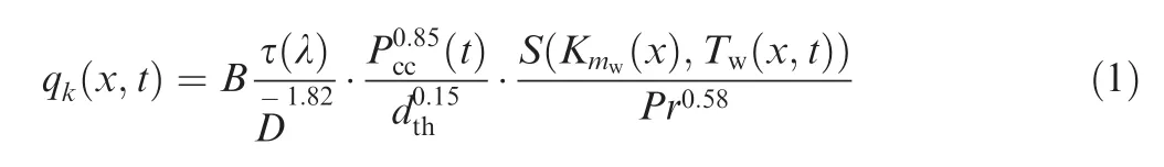
wherexis axial coordinate,tis operation time,Bis coefficient taking into account the transition from viscosity μ0Gto viscosity μ1000Gat a temperature of 1000 K, τ(λ)is gas-dynamics function,Pcc(t) is combustion chamber pressure,S(Kmw(x),Tw(x,t))is function of thermophysical parameters of gas,which depends on the type of fuel,the ratio of components in the near wall layerKmw(x)and temperature of wallTw(x,t),is relative diameter,dthis throat diameter of combustion chamber,andPris Prandtl number.
The model cannot predict whole temperature field of combustion chamber because they do not operate with Navier-Stokes equations,and there is no need to calculate the whole field.Instead of this,the model predicts the near wall parameters that directly affect heat transfer.The model uses solutions of the boundary layer equations including continuity equation,equations of momentum,energy,friction,chemical equilibrium,enthalpy and viscosity and others.The differential equations of the turbulent boundary layer are used to compile integral equations and then transform it to question(1).
The convective flow is determined by the parameters of the combustion products near the wall,taking into account the mixing of the wall layer with the film cooling layer.When there is internal film cooling,it is necessary to use the parameters of the combustion products,determined by the ratio of the components near the wallKmw.
The radiant heat flux from the combustion products to the inner wall surface and from the outer wall surface to the environment is calculated according to the Stefan-Boltzmann law the radiation power is directly proportional to the fourth power of the body temperature:

where φfcis the coefficient the absorption of the radiant flux from the core of the combustion products through the near wall layer,εw.ef.is the effective coefficient of blackness of the wall material,εgis the coefficient of emissivity of gas,C0is the Stefan-Boltzmann constant,TkandTware the static core and wall temperatures(changing by time)on the gas side,respectively.
If there is internal cooling of the wall by organizing the film cooling with a fuel or an oxidizer,it is necessary to calculate the length at which the film remains in the liquid state.The length of the evaporation section of the film can be determined from the balance:the heat transferred from the combustion products to the liquid film goes to its heating and evaporation14:
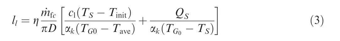
where η is the coefficient that takes into account the process of partial tearing of the film from its wall surface(0.5-0.9),˙mfcis the mass flow of liquid film cooling,πDis the circumference of the combustion chamber,Tinitis the initial temperature of film liquid,TSis the boiling temperature of the liquid at a given pressure in the combustion chamber,clis the specific heat capacity of liquid at medium temperature,Tave=(Tinit+Ts)/2,Qs,is the heat of evaporation of component,and αkis the convective heat transfer coefficient,calculated without allowance for curtain cooling:

whereTG0is the temperature of the gas in the wall layer andTwGis the wall temperature,which depend on the ratio of the components in current calculation section,if the film cooling is absent.The coefficient η depends on the hydrodynamics of the film flow and its interaction with the main flow η=f(Refc),Refc=ρ1W1δ1/μ1=m˙fc/(πDμ1),where ρlis the film liquid density,Wlis the average velocity of film cooling liquid,δlis the thickness of film cooling,and μlis the liquid viscosity.
When modeling the thermal state of the combustion chamber wall,it is necessary to correctly set the conditions for external convection.When modeling the thermal state with vacuum conditions,external convection is excluded.When modeling under atmospheric conditions,it is necessary to analyze the external conditions acting on the heat exchange process.The external convective heat flux is calculated according to the following equation:qk.ext= αk.ext(T-T∞)where αk.extdetermines the intensity of heat exchange between the outer wall surface and the environment,Tis the temperature of the outer wall surface,T∞is the temperature of the environment.For natural convection,αk.ext=2÷25( J/s·m2·K),and for forced convection, αk.ext=25÷250( J·s·m2·K).The exact definition of αk.extis very difficult because in the test conditions and the working place there are a large number of factors affecting the heat transfer:ambient temperature,engine location,air velocity on the surface of the combustion chamber,etc.In this calculation, αk.ext=2÷ 25( J/s·m2·K),which is typical for turbulent natural convection.
Except formula(1),heat convection in thrust chamber can be calculated by formula Bartz(5).The formula describes the relationship between heat convection intensity and fluid's physical features as well as flow behavior.Gas-side heat transfer coefficienthgis expressed by
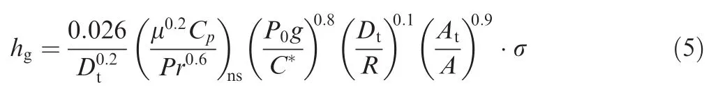
WhereDtis throat diameter,μ is the viscosity of gas,ns means nozzle stagnation condition,Cpis the specific heat capacity at constant pressure,P0is chamber pressure,C*is characteristic velocity,R=(Rtin+Rtout)/2 is the radius of curvature of nozzle contour at throat,AtandAare area of throat and calculated section respectively,and σ is the correction factor for property variations across the boundary layer and can be evaluated in terms of nozzle stagnation temperatureT0,local gasside chamber wall temperatureTw,specific heat γ,and local Mach numberMa:

Quantity of heat convection is indicated by effective temperature:

whereTgthe temperature of the gas in the wall layer.
The calculation shows that Ievlev and Bartz equations for the same conditions have most likely results;the results of convective heat flux are shown in Fig.1.The difference is less than 10%for throat section and less than 1%for other section.In the future,we will use Ievlev approach for heat flux calculation.
When simulating engine cooling after the tests are completed,it is necessary to take into account the possible purging procedure and,consequently,the presence of forced convection between the internal wall of the combustion chamber and the purge gas,in this case a convective heat transfer coefficient value is required.
To solve the nonstationary heat transfer problem,the differential Fourier-Kirchhoff thermal conductivity equation is used in the case of a stationary flow and the absence of internal heat sources in cylindrical coordinates15:
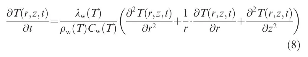
where λw(T),ρw(T),Cw(T)are thermal conductivity,density and heat capacity of the wall material of the combustion chamber as a function of temperature respectively,ris the geometrical size of the dimension(radius),zis the geometric size of the longitudinal dimension(step along the radius).
To obtain a difference analogue,we will write the partial derivatives with allowance wherekis the time step,iis the number of the grid node along the axis of the shell,jis the grid node number perpendicular to the axis,Δzis the step along the axis,and Δriis the step along the radius in the cross section:

The difference analogue of the equation will have the form:
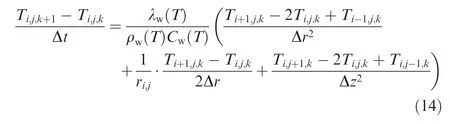
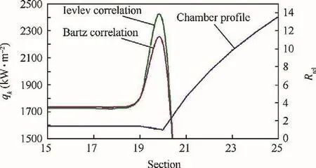
Fig.1 Ievlev and Bartz approaches in result of convective heat flux.
For the solution,initial conditions are set up in the form of a temperature distribution on the surfaces and in the wall of the combustion chamber,and the boundary conditions in the form of the dependences of the change in the heat flux on the inner and outer surfaces of the combustion chamber and also at the ends on the side of the mixing head and the nozzle section.The methodology and calculation formulas used in the mathematical model are considered in more details in previous works,11,12 and the structural scheme is shown in Fig.2.
As any kind of mathematical models,this model has limitation and assumptions.Foremost,as mentioned above,only near wall layer is calculated exactly,and the kernel layer seems to be stationary and uniform.
4.Modeling pulsed mode of operation
A typical experimental cyclogram of a single pulse of a thruster with a command signal duration of 0.1 s is shown in Fig.3.
The operation of the engine can be divided into the following characteristic areas and points:
(1)I-supply of voltage to the valves,the beginning of their opening,the flow of liquid components into the mixing head,the full opening of the valves and the final filling of the mixing head by the components;pointa-receipt of the first portions of fuel components into the combustion chamber volume.
(2)II-entering of the first portions of the components in the combustion chamber,pre- flame processes and the increase of pressure to the level of 0.1 Pkdue to the fuel injection without the combustion processofthe propellants.pointb-ignition of propellants,engine thrust uprising;

Fig.3 Cyclogram of operation of thruster with a command signal duration 0.1 s.
(3)III-combustion of fuel and oxidizer with the formation of the main products of the reaction, filling the combustion products with a volume of combustion chamber and increasing the pressure up to a level of 0.9 from the nominal pressure Pk;pointc-engine output for full thrust pulse.
(4)IV-engine operation in steady state;pointd-engine output level of nominal thrust.pointe-command to close the valves;pointf-actual closing of valves.
(5)V-burn-out of components flowing from the trapped cavities of the mixing head-the end of the combustion process;pointg-pressure in the combustion chamber drops down to 0.9 Pk.

Fig.2 Structural diagram of mathematical model.
(6)VI-emptying the volume of the combustion chamber with the remaining propellant components and gases of the combustion products.
Characteristic parameters of the pulsed operating mode are16:
τST-electric signal time on thruster valves;
τP-pause time between starts of single thruster;
τPB-post burning time to 0.9Pk;
τPS-post electric signal time to 0.1Pk;
T-cycle time between starts of single thruster T= τST+ τP.
The time parameters related to the time of pulse interlacing form the dimensionless parameters of the pulsed mode of the thruster:
k=τST/T- filling factor;
S=τP/T-duty cycle;
f=1/T-frequency of working of thruster17,18
According to the pulsed mode of the thruster,the problem of modeling the conjugate heat transfer is divided into two problems5,6,19:modeling heat transfer in the steady-state mode of the pulse and modeling heat transfer in unsteady mode in a quasi-stationary formulation.For the second case,equations for the steady-state mode are used with correction of changing thermodynamic parameters of combustion products' flow:pressure and temperatures.
To solve the task,the process of growth and pressure drop is replaced by a set of dependencies:
(1)The process between the points of supply of voltage to valve 0 and pointbis not modeled,the process of calculating the thermal state will start according to the calculated time delay;
(2)The process of pressure growth is modeled by a linear relationship with known points (τ0.1;0,1Pk)-(τ0.9;0,9Pk),which are user-defined;
(3)The steady-state process is modeled according to the stationary approach;
(4)The process between the pointeand pointgis the conditional time of post-burning τPB,modeled according to the stationary approach,and τPBis set by the user;
(5)The process of pressure drop to the end of the pulse is modeled by quadratic or exponential interpolation from known points( τST+ τPB;0,9Pk)- (τST+ τPS0,1Pk);
(6)The process after τPSis not modeled.
This approach allows avoiding the connection between the process of electromechanical opening-closing of the solenoid valve and the processes occurring in the mixing head and combustion chamber at the time of engine startup and shutdown.Values of the parameters τ0.1,τ0.9,τPBand τPSare set directly by user,using theoretical or previously obtained statistical characteristics of the operation of a particular thruster or analogs.
The pressure drop in startup period when combustion chamber comes to the steady-state operating mode and pressure fluctuations during the engine operation can be neglected,assuming that short-term pressure pulsations do not exert a large influence on the thermal state of the chamber wallthe calculation is based on the steady-state average pressure in chamber.
Such an assumption restricts the applicability of the mathematical model,which is used only for steady-state pulse engine operation.For unsteady pulse modes of operation,modes with cut pulse,where the proportion of nonstationary processes is large enough,regression models based on statistical testing of the results of fire tests of thrusters should be used to determine the thermal state of the chamber wall and the engine's energy parameters.
5.Object of investigation and initial data for calculation
The initial data for the calculation were the parameters of the low-thrust rocket engine developed in the Moscow Aviation Institute,nitrogen tetroxide and asymmetric dimethyl hydrazine,200 N of thrust.The engines of this dimension,on these fuel components,are most often used as executive controls for the reactive spacecraft control system.20-22
The experimental engine DMT MAI-200-1(Fig.4)has a removable mixing head,which is fixed to the body of the combustion chamber by a flange connection.The sealing of the flange-mixing head was carried out using a copper ring.The head of the engine DMT MAI 200-1 has one two-component centrifugal jet and a slotted film cooling along the circumference,which provides protection of the walls of the combustion chamber(Fig.5).
The main characteristics of the engine MAI-200-1 are as follows:
(1)Thrust-200 N;
(2)Working time-50 s;
(3)Components: nitrogen tetroxide+unsymmetrical dimethyl hydrazine(AT+UDMH);
(4)Specific pulse without film cooling-292 s;
(5)Coefficient of completeness of combustion-0.92;
(6)Working pressure in the combustion chamber-0.94 MPa;
(7)Degree of expansion of the nozzle by pressure-1060;
(8)Mixing ratio of components-2.6;
(9)Total mass flow rate-0.066 kg/s;
(10)Film cooling component-fuel;
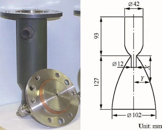
Fig.4 Combustion chamber with mixing head and geometry profile of LREST MAI-200-1.

Fig.5 Design of single-jet mixing head of engine MAI-200-1.
(11)Relative mass flow for film cooling(by sum mass flow)-20%.
6.Results of experiments in single-turn-on mode
For the simulation of the pulsed mode,the initial data for the calculation and the time parameters are set(τ0.1,τ0.9,τPBandτPS)which are taken based on the results of the fire tests of the MAI-200-1 in the single-turn-on mode of different duration(from 2 to 50 s).
During the tests,thruster with a shortened nozzle is used.The test scheme without a nozzle part allows checking the efficiency of the combustion chamber itself for long-term work without the involvement of expensive vacuum equipment.As shown by the calculation of the thermal state of the chamber with the nozzle,the presence of the nozzle part does not significantly affect the thermal characteristics of the combustion chamber.
The stand(Fig.6)is equipped with a special working area,which includes a frame 2 for securing the engine in a vertical position,a protective casing 7 and a gas-dynamic cooled pipe 1 for flue gas discharge to the stand neutralization system.The combustion chamber of the engine 4 with the installed head and thermocouples is fixed to the frame of the working area with the aid of three pins passing through the head flange.
The main sensors used to analyze the working process in the engine are:
(1)Two sensors for measuring the pressure in the chamber;
(2)Two turbine sensors for measuring mass flow of fuel;
(3)Two turbine sensors for measuring mass flow of oxidizer;
(4)Thermocouples mounted on the outer surface of the chamber(4 section with 2 reverse thermocouples for each section);
(5)Two pressure sensors at the engine inlet(in front of the valves);
(6)Two thermocouples for measuring the temperature of the components at the entrance to the engine;
(7)Two current measurement of electromagnet valve.
Comparison between the results of experiments and calculations of the thermal state of the combustion chamber wall in the single-start-up mode is shown in Figs.7 and 8.
Calculations of the thermal state of the combustion chamber show good convergence with the experimental results of LREST MAI-200-1 at the level of 5-10%.The discrepancies are explained by the following reasons:
(1)The real boundary conditions differ from the functions adopted in the calculation of the boundary conditions qk(x,t)and qrad(x,t),and the real boundary conditions are more complex and then adopted in mathematical model;
(2)At the initial moment of time,the exact definition of the boundary conditions is problematic because of the unsteady combustion and near wall processes in the chamber.

Fig.6 Schematic diagram of fire stand.
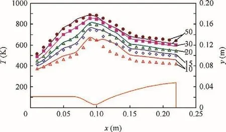
Fig.7 Comparison between experimental(interpolation points)and calculated(lines)temperature of external surface of combustion chamber by time(current time in seconds displayed in gray square).

Fig.8 Comparison between experimental(interpolation points)and calculated(lines)temperature of external surface of combustion chamber by time in different sections.
(3)Thex=0.12 m section was near exit section of nozzle and near gas-dynamic cooled pipe(see Fig.6,position 1).When engine works,the nitrogen passes through protective casing(see Fig.6,position 7)into cooled pipe near exit section of nozzle right near thermocouplex=0.12 m that can be the reason of decrease of real temperature wall.
The calculation results and test data show that the most heat-stressed place is the wall near critical section.The highest rate of growth of temperature is in the same place.It agrees with the theoretical issue.
One can draw a conclusion about the adequacy of the numerical solution of the nonstationary heat conduction problem for a single launch.This enables us to use the mathematical model for further calculations of the pulsed mode in the quasi-stationary formulation of the problem.
7.Results of calculation of a thermal state in a pulsed mode of operation
Figs.9 and 10 show the results of mathematical modeling of the thermal state of the combustion chamber wall of the engine in a pulsed steady-state mode,for the case of 20%of the fuel film cooling and α=0.85 for different pulse duration and pause time at a duty ratioS=0.5.In the calculation,the operating conditions of the engine with a cut nozzle are simulated under the conditions of an atmospheric fire stand.It is assumed that a vertical installation of the engine,and mutual radiation between the combustion chamber and the elements of the stand,are excluded.The ambient temperature is 300 K.The values of the characteristic time are taken as follows: τ0.1=0.01 s; τ0.9=0.02 s; τPB=0.01 s; τPS=0.03 s.Fig.9 also shows the change of pressure with calculation time.
In the case of pulsed operation,a cyclic thermal action is observed on the inner surface of the chamber.When the engine is switched off,the heat is redistributed from the more heated layers(inner surface of the wall)to the less heated layers(outer surface)and from the more heated zones(subsonic part of the nozzle)to the less heated(cylindrical part of the combustion chamber).The layers that are closer to the inner surface of the chamber work with a large temperature amplitude,which decreases with subsequent heating of the wall.Thus,coatings that are used in the production of thruster must have sufficient strength and adhesion properties,allowing them to work in the conditions of cyclic exposure to temperatures and combustion products.
Figs.11 and 12 show the simulation results of the operation of the engine on a firing atmospheric stand by a composite cyclogram:a single pulse of 10 s,5 pulses of 2 s with 2 s interval,5 pulses of 1 s with 1 s interval,and purging the engine by nitrogen.Fig.12 shows the change of the temperature of the outer surface of the combustion chamber wall in different sections for this operating mode.
The results of calculation(Figs.11 and 12)clearly show the influence of the cycle time between single inclusions on the thermal state of the combustion chamber wall for different sections.The critical sectional area during the transition to the pulse mode stops being heated,and as the interval time increases,the wall temperature decreases.The zone of the cylindrical part of the combustion chamber continues to be heated during the transition to the pulse mode of the engine,There is no experimental verification of this result,but we will plan in future.
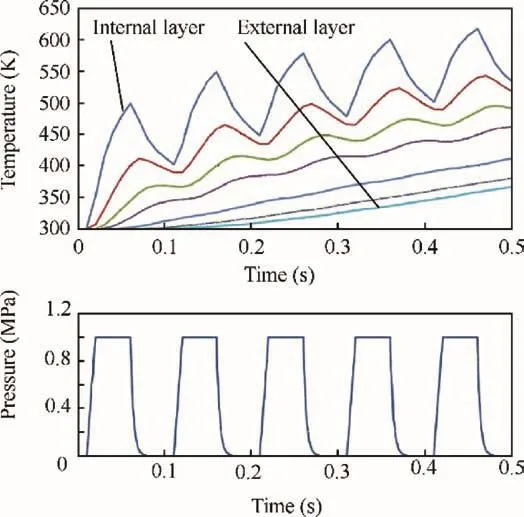
Fig.9 Variation of wall temperature of combustion chamber in critical section with time.(Pulse duration 0.05 s,interval time 0.05 s,20%of fuel film cooling,α=0.85).
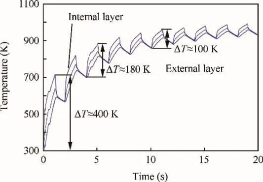
Fig.10 Variation of wall temperature of combustion chamber in critical section with time.(Pulse duration 1 s,interval time 1 s,20%of fuel film cooling,α=0.85).
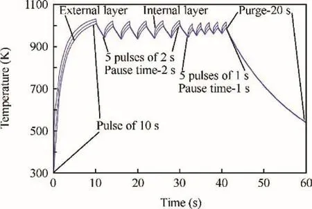
Fig.11 Variation of wall temperature of combustion chamber at critical section with time when modeling composite engine operation cycle.

Fig.12 Variation of temperature of external surface of combustion chamber wall in different sections with time for modeling composite operation cycle of engine.(x=0.04 m-combustion chamber,x=0.09 m-critical section,x=0.12 m-out of short nozzle).
In fact,it is possible to use model to predict thermal state of any thruster.For doing this,the engineer should set up(or calculate)geometry and thickness of wall,injector pattern, film cooling parameters,materials,propellants,chamber pressure,mixture ratio and others.If any single-turn-on mode exists,it allows the adjusted model to have more accuracy for thermal prediction.The new results using this model show that it can be possible to get dependencies of thermal state of combustion chamber from any general parameter of engine and working mode.There are more than 50 parameters,excluding dataset of materials,chemical elements,propellants and others.The model is a hopeful tool for engineer of space propulsion system and can be extended.For example,based on this model,the calculation of regenerative cooling of liquid rocket engine(including transient heat transfer during filling up the cooling jacket of coolant)is done.For verifying the model,the experimental data are now collected and systemized.
8.Conclusions
(1)A mathematical model that allows predicting the thermal field of a combustion chamber wall in various engine operating modes is developed.The physical processes taking place in the engine for startup and shutdown mode are considered.
(2)A theoretical study of the thermal state of a model liquid rocket engine operating in a pulse steady-state mode has been investigated.The cases of engine operation in pulsed modes with different cycle time between single inclusions are considered,as well as a mode simulating fire tests at an atmospheric stand with varying time of single pulses.
(3)A large temperature amplitude is obtained on the internal surface of the combustion chamber when calculating the pulsed mode.On the first pulse,the amplitude of the temperature is approximately 400 K,and then the amplitude decreases noticeably and reaches values of up to 100 K,which indicates that the thermal state of the wall in a pulsed steady-state mode strongly depends on the pulse duration and the interval between the operations.
(4)The mathematical model can be used for modeling thermal state of thruster with various propellants,mixing scheme,geometry of combustion chamber and nozzle,and material of wall,including wall coating.
杂志排行

CHINESE JOURNAL OF AERONAUTICS的其它文章
- A review of chatter vibration research in milling
- Impact of reduced frequency on the time lag in pressure distribution over a supercritical airfoil in a pitch-pause-return motion
- Sliding mode control design for oblique wing aircraft in wing skewing process
- Adaptive optimization methodology based on Kriging modeling and a trust region method
- Aircraft engine fault detection based on grouped convolutional denoising autoencoders
- Predicting lean blow-off of bluffbody stabilized flames based on Damköhler number