Numerical investigations of the effects of blade shape on the flow characteristics in a stirred dead-end membrane bioreactor *
2019-01-05XuquHu胡徐趣XingyiWang王星燚XiuchengLei雷秀成XiangQiu邱翔LinfengChen陈林烽
Xu-qu Hu (胡徐趣), Xing-yi Wang (王星燚), Xiu-cheng Lei (雷秀成), Xiang Qiu (邱翔),Lin-feng Chen (陈林烽)
1. State Key Laboratory of Advanced Design and Manufacturing for Vehicle Body, College of Mechanical and Vehicle Engineering, Hunan University, Changsha 410082, China
2. College of Science, Shanghai Institute of Technology, Shanghai 201418, China
3. School of Naval Architecture and Ocean Engineering, Jiangsu University of Science and Technology,Zhenjiang 212003, China
Abstract: Numerical simulations of turbulent flows in a stirred dead-end membrane bioreactor are performed by using the RNG -εk model based on the finite volume method with the software Fluent. Comparisons of numerical and experimental results confirm the reliability and the feasibility of the constructed model. The flow structures such as the wake flows and the circulation loops in the stirred flows are well simulated. An increase of stirring speed is proposed to minimize the low velocity region. The single vane stirrer is found to be beneficial for biological separations. Results suggest that the increase of the vane number can enhance the mixing effect in the flow domains. However, a circular disk stirrer goes against the formation of vertical circulations. The six-vane stirrer is found to be able to provide a uniform distribution of the high shear stress.
Key words: Turbulent flow, stirred flows, membrane fouling, membrane bioreactor
Introduction
The membrane filtration is widely applied in many industrial separation treatments, such as the wastewater treatment and the biological separation[1].For biological separations, the membrane bioreactors(MBR), consisting of a submersed micro-porous membrane to filtrate the feed solution by forcing it to permeate through the membranes, are considered tobe most efficient[2]. As the suspending materials will eventually be deposited on the membrane surface,either the pore blockage or the cake-layer formation on the membrane surface can lead to a significant flux decline and the rapid membrane degradation[3]. The membrane fouling is a significant issue for the widespread use of the membrane filtration techniques.During the past several decades, many strategies were proposed to control the membrane fouling, such as the membrane washing and cleaning[4], the gas sparging[5]and the dynamic filtration[6].
The dynamic filtration, also known as the shear-enhanced filtration, is to alter the hydrodynamic characteristics and to produce high shear rates by a moving part near the fixed membrane in the container[7]. Comparing with the conventional cross flow filtrations, the dynamic filtration is usually operated at a moderate trans-membrane pressure (TMP)and a small inlet flow rate. Its total cost is normally lower than that of the conventional techniques, since the specific hydrodynamic characteristics in the dynamic filtration systems is beneficial for the energy conservation, the membrane fouling control and the investment reduction[8]. An increasing number of researches examined the hydrodynamic characteristics and the membrane fouling mechanism in the dynamic filtration systems using experimental and numerical techniques, e.g., in Ref. [6]. Yang et al.[9], Hu et al.[10]utilized a rotating solid disk to create high shear rates in the dynamic filtration bioreactors to concentrate the recombinant yeast cells. The stirring speed was found to be one of the key factors for the flow characteristics in reactors. Jiang et al.[11]experimentally studied the relationship between the rotating speed and the membrane fouling using the particle image velocimetry. It was suggested that the increase of the rotating speed is an effective and energy-saving method for preventing the membrane fouling, as it could induce the intensive turbulent flow in the reactor. Torras et al.[12-13]numerically studied the shear stress distribution on the membrane surface in the rotating disk filtration modules. The results obtained by the commercial software Fluent agree very well with the experimental data, which implies that the numerical techniques are suitable for the hydrodynamic studies of the dynamic filtration systems. Parvareh et al.[14]applied the renormalization group (RNG) -kε model to study the turbulent flow in a microfiltration module with marine type impellers, in which the permeate flux is found to be closely related with the flow characteristics and the dynamic pressure distribution on the membrane surface.
The stirring blade shape is closely related with the generated flow characteristics in the membrane reactors, and can be used to determine the optimal operating conditions in the dynamic filtration process.Brou et al.[15]constructed an experimental equipment for the microfiltration of the yeast suspensions by integrating vanes to the rotating disk. They found that the introduction of vanes to the disk surface can generate a highly permeate flux to prevent the membrane fouling, as it enhances the mixing effect by generating more vortices near the membrane surface.Sen et al.[16]studied the effect of the vane geometry on the shear stress distribution on the membrane surface in a rotating disk module, in which the maximum permeate flux was found to be achieved by the 45°angle perforated vanes. Hwang and Wu[17]focused on the shape effect of the rotating disk (e.g., the vane number) on the flow characteristics in a microalgae microfiltration system. The filtration performance is found to be intensively affected by the disk structure and the rotation speed. Kim et al.[18]numerically studied the flow domain generated by the perforated or unperforated disks in a dynamic filtration system to harvest microalgae, which is confirmed to generate high shear rates on the membrane comparing to the device with an unperforated disk. Sarkar et al.[19]designed a novel shear enhanced membrane module,consisting of a hollow basket with four radial arms and installing on the central shaft. The numerical results indicate that the accumulated solute is dispersed from the membrane surface due to the intensive circulation flow generated by the basket rotation. However, to our best knowledge, we still have a limited number of numerical studies about the effects of the blade shape on the hydrodynamic characteristics in an enzymatic bioreactor.
In this study, we focus on the effects of the blade shape on the hydrodynamic characteristics in a widely used enzymatic bioreactor. A three-dimensional numerical model is constructed to simulate the stirred turbulent flows in an enzymatic bioreactor equipped with membrane. The computational fluid dynamics(CFD) software Fluent are applied for numerical simulations. The features of the stirred flows by a straight-vane stirrer are firstly analyzed. The flow velocities, the TMP and the shear stress distribution are all discussed. The flow characteristics induced by different blades (with different vane number) at different stirring speeds are examined. The collaborating effects of the blade shapes and the stirring speeds, on the shear stress distribution on the membrane surface, are analyzed. An optimal situation is determined in terms of the highest and most-uniform distribution of the shear stress on the membrane surface.

Fig. 1(a) Schematic diagram of an enzymatic split drawing of device
1. Methods and models
1.1 Problem description
We study the stirred flows in a dead-end enzymatic membrane bioreactor (Amicon 8050, Millipore,USA), widely applied for the separation treatments in bioengineering. As shown in Fig. 1(a), the membrane module of 45 mm in diameter is fixed at the bottom of a cylindrical container. The total height of the container is 98 mm. A blade is mounted at the end of a straight shaft, which can be magnetically rotated to generate a rotating flow, with high shear stress near the membrane surface. The gap between the membrane surface and the bottom of the blade is 4 mm.
It is assumed that the pure water, acting as the feed solution, is continuously pumped into the container from the inlet. The feed solution is forced to flow towards the bottom of the container under the pressure-driven effect. An ultrafiltration membrane(RC10-M, PLGC, Millipore, USA) is settled on the membrane module, to allow the pure water to penetrate through but to obstruct large molecular particles inside the container in the separation treatments. At the bottom of the container, an array of blades is applied to generate high-speed rotation flows. Five different types of stirring blades are considered to investigate the effect of the blade geometry on the hydrodynamics in this stirred flow. The blade shapes are demonstrated in Fig. 1(b), which are named the straight-vane stirrer (SV), the three-vane (3V) stirrer,the four-vane (4V) stirrer, the six-vane (6V) stirrer and the circular-disk (CD) stirrer, respectively. For the SV, 3V, 4V and 6V stirrers, the blade length and height are 36 mm and 12 mm, and the blade widths are all 4 mm. The radius of the CD stirrer is 36 mm,and its height is 12 mm. The blade rotation speed is assumed to be 150, 200 and 400 rounds per minute(rpm).

Fig. 1(b) Schematic diagram of an enzymatic different types of stirring blades
1.2 Numerical model
The stirred flow is governed by the Navier-Stokes equations:


where u denotes the velocity, p is the pressure,f is the body force and μ is the dynamic viscosity.As it is stirred at high rotating speeds, the fluid flow in this reactor is under a relatively high Reynolds number. The turbulent effect should be taken into account in our modeling. We apply the RNG -kε turbulence model, which is initially derived by Yang et al.[20], Qin et al.[21]based on the renormalization group theory. Although it is in similar forms to those of the standard -kε turbulence model, the empirical nature of the turbulent flow is considered and the turbulent viscosity and dissipation rate equations are modified to better describe the rapidly strained flows,such as the stirred flows[22]. The RNG -kε turbulence model is widely used for the turbulent flows[23].The turbulent kinetic energy and dissipation rate equations can be expressed as:

where the modified viscosityis equal to the sum of the dynamic viscosity μ and the eddy viscosity tμ, andcan be expressed asuseto represent the generation of the turbulence kinetic energy due to the mean velocity gradients,which is written as


As is viewed from the stationary frame, the stirred flows around the shaft can be considered as unsteady flows. However, some approaches with a moving reference frame can be employed to simplify the flow around the moving part as a steady-state problem, such as the single reference frame (SRF) and multiple reference frame (MRF) approaches[24]. The accuracy and the reliability of the SRF and the MRF for rotating flows were validated in several studies,e.g., Yataghene et al.[25], Hu et al.[26]. The SRF approach is applied in the present study.

Fig. 1(c) (Color online) Schematic diagram of an enzymatic corresponding mesh
1.3 Numerical simulations
The CFD software Fluent 15.0 is applied for the numerical simulations of the stirred flow in the reactor.It is based on the finite volume method, in which the flow domain is discretized into a finite set of control volumes. The pressure-based and implicit numerical solver is applied in the simulations. The SIMPLE algorithm is used to deal with the pressure velocity coupling process. A constant pressure of 200 kPa is applied at the inlet, while the atmospheric pressure is applied at the outlet. The physical behavior of the RC10-M membrane is assumed to be equivalent to that of a porous media, to allow the water to pass through. The effect of the membrane resistance is described by the Darcy’s law, where the resistance coefficient is determined based on our experimental results. As shown in Fig. 1(c), the flow domain is discretized by an unstructured tetrahedral mesh with about 3.1×10⁶unites. In order to achieve a high accuracy at a relatively low computational cost, a fine mesh with a characteristic length of about 0.3 mm is used for the membrane domain and that near the blade surfaces, while a coarse one with a characteristic length of about 1.7 mm is applied in the region close to the inlet. The influence of the mesh size is validated using a twice-smaller mesh, with no significant difference being observed in between.
1.4 Validation
An experimental investigation of the relationship between the flux and the TMP was reported for the same reactor[27-28], where it is found that the flux increases linearly with the TMP for the RC10-M membrane. It means that the membrane filtration resistance is constant, which is adopted as the reference for the determinations of physical parameters of the porous media (the membrane) in the present numerical model. The variations of the flux with respect to the TMP, obtained from experimental or numerical approaches, are shown in Fig. 2. It is shown that the experimental and numerical results are in good agreement, which validates the reliability and the feasibility of the proposed numerical models.

Fig. 2 Comparison of numerical and experimental results of flux ( )M to transmembrane pressure
2. Results and discussions
The fluid velocity and the shear stress near the membrane surface are important for the transportation and the deposition of the pollution materials in MBR,and consequently are the critical factors for preventing and controlling the membrane fouling. A typical technique to generate the flow fields as required is to apply a rotating module (e.g., a straight-vane stirrer or a perforated disk) near the membrane surface in the filtration systems[15-17]. The hydrodynamic characteristics of the stirred flows are closely related with the blade stirring speed. The internal flows in a dead-end membrane reactor driven by a straight-vane stirrer at different rotation speeds are therefore simulated by our constructed models.
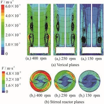
Fig. 3 (Color online) Velocity distributions in a stirred reactor
Figures 3 (a), 3(b), respectively, show the fluid velocity distributions in vertical and horizontal planes,for which the stirring speed of the straight-vane stirrer is 150 rpm, 250 rpm and 400 rpm from left to right. It can be noted in Fig. 3(a) that the internal fluid is driven by the radial discharge from the blade to rotate and to flow centrifugally towards the container wall.The centrifugal jet splits into two main tributary flows near the small gap between the blade tip and the sidewall of the container, with the fluid velocity being higher near the blade tips than in the central part of the reactor. One upward spiral flow migrates towards the inlet, and the other downward spiral flow rotates near the membrane surface. A strong circulation loop extending over a large volume from the inlet to the top of the blade can be found around the shaft, which is mainly formed by the merging of the upward spiral flow and the inflow of the feed-water. These flow patterns were also identified by many previous studies using experimental and/or numerical techniques for other dynamic filtration systems of different types of stirrers[13,22]. As the stirring speed increases from 150 rpm to 250 rpm and to 400 rpm, the internal flow can be apparently accelerated as the overall color distributions of the fluid velocity become lighter and brighter (Fig. 3). Since a high fluid velocity is beneficial for preventing the membrane fouling, our results agree with the practical experience that the increase of the blade stirring speed is an effective strategy to improve the membrane performance[9-10]. However, a low velocity region in the color of light blue can always be found in Fig. 3(b) at the regional center of the membrane surface, despite the fact that it shrinks as the stirring speed increases. As the membrane fouling would likely accumulate at the region of low fluid velocity, in a better design of blade geometry, the low velocity region area on the membrane surface should be reduced for the efficient use of the membrane,especially for those biological filtrations that are only allowed to be operated at low stirring speeds.

Fig. 4 (Color online) Velocity distributions on vertical planes for five geometries of stirring blade at 150 rpm
For a low stirring speed of 150 rpm, the internal flows induced by different shaped stirrers are simulated by the proposed model. Figure 4 shows the distributions of the fluid velocity on the vertical planes, where the stirrer shapes are the SV, the 3V, the 4V, the 6V and the CD, respectively, as shown in Fig.1(b). The circulation loops that are merged by the upward spiral flow and the feed-water inflow can be found for all stirrers. The top ring vortices inside the circulation loops are almost symmetric about the shaft in the SV case with an almost horizontal centrifugal flow jet, as in contrast with the 3V case, where the top ring vortices on the left side are inclined towards the membrane surface with a relatively large vortex persisting at the bottom left corner of the container.This difference is primarily due to the asymmetric arrangement of the vanes of the 3V stirrer on the horizontal plane. As the number of vanes increases from 1-6, the area of high flow velocity near the blade tips becomes larger and thicker, but no significant changes of the overall color of the fluid velocity can be found. It implies that increasing the vane number is not an effective way to accelerate the overall internal flow fields. However, the vortex structure varies significantly with the increase of the vane number.The layered ring vortices on the top of the blade are found to merge gradually as the stirrer type varies from SV-3V-4V, and finally to expand over almost all circulation loops for the 6V stirrer. This result indicates that the flow mixing effect can be enhanced if more vanes are applied. For the CD stirrer, it is of interest to notice that the flow domain is separated into two parts: the upper circulation loops above the stirrer and the lower vortex flow rotating near the membrane surface. The vertical convection flow is almost completely restrained by the CD stirrer, and the overall flow velocity is therefore significantly lower than that of other stirrers.

Fig. 5 (Color online) Distributions of flow velocities at 150 rpm on different horizontal planes
Figure 5 shows the distributions of the fluid velocity on different horizontal planes with a counterclockwise stirring speed of 150 rpm. The structures of the upward/downward flows can be more clearly seen on horizontal views. Taking the case of the SV stirrer for example, as shown in Fig. 5(a), the fluid velocities on the membrane surfaceare very low as the downward spiral flow is decelerated under the effects of the wall friction. On a horizontal plane that cuts the stirrerthe wake flows can be clearly identified at the le eward sid e of the impeller blades, in whichthefluidvelocitiesaresignificantly higher than those in other areas. An elliptical vortex can be found on the horizontal plane above the SV stirrer (y = 20 mm), which is mainly created by the upward spiral flow. As the vane number increases, the vortex structure changes to a triangular-like shape for the 3V stirrer, a square-like shape for the 4V stirrer and a circular-like shape for the 6V stirrer. Moreover,the area of the wake flows is also observed to expand with the increase of the vane number, as it takes over almost all the peripheral area of the circular plane with the 6V stirrer, as shown in Fig. 5(d2). These results are in consistence with the experimental observations that the increase of the vane number can enhance the mixing effect of the stirred flows. However, Fig. 5(e)shows that the flow velocities induced by the CD stirrer are much lower than those of other stirrers,therefore, the CD stirrer might be regarded as the extreme case of the increase of the vane number. This divergence between the numerical results and the physical deductions, are mainly caused by the restrained effect of the mixing flows. As shown in Fig.5(e2), the circular disk almost blocks the cylindrical reactor, which is not beneficial for the formation of the vertical mixing flows.
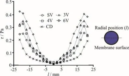
Fig. 6 (Color online) Distributions of shear stress along the radial line ()l on membrane surface at 150 rpm
The distributions of the shear stress along a radial line on the membrane surface at 150 rpm are presented in Fig. 6. The shear stresses are almost zero in the central area of the membrane, but it increases rapidly on the radial direction to the peripheral area of the membrane. The maximum shear stress occurs near the marginal area of the membrane. This non-uniform distribution of the shear stress along the radial direction is mainly due to the uneven distribution of the flow velocities. A sharp decrease of the shear stress in the marginal area can be observed in most of these cases, which is caused by the complex flow behaviors in the gap between the blade tip and the container wall.

Fig. 7 (Color online) Distributions of shear stress on membrane surface at different stirring speeds
Figure 7 shows the shear stress patterns for different blade geometries at each stirring speed. Firstly,with the increase of the stirring speed, for each stirrer,its effect on the shear stress is clear for groups (a)-(e).As illustrated in Fig. 7(a1), the magnitude of the shear stress on the membrane surface of the SV stirrer at 150 rpm remains at a low value ranging from 0 Pa to 0.37 Pa, which is due to the effect of the wall friction as mentioned above. As shown in Fig. 7(a2), because the downward spiral flow is strengthened by the increase of the stirring speed, the magnitude of the shear stress in the peripheral area of the circular plane is apparently larger than that in the central area. The maximum value increases to approximately 1.06 Pa at 250 rpm. As the stirring speed increases to 400 rpm,as shown in Fig. 7(a3), the shear stress in the peripheral area becomes higher, and its value reaches about 2.13 Pa. In addition, it can be seen that the downward spiral flow in the peripheral area is dragged by the blade tips and moves in a counter-clockwise direction. Secondly, as the vane number increases, it can be seen that these downward spiral flows are restrained in a specific area. Especially for the 6V stirrer, they nearly hold all the peripheral area of the circular plane, as shown in Fig. 7(d3). Moreover, the shear stress distributions become increasingly uniform for SV to 6V stirrers. Specially, Fig. 7(e) shows that the shear stress induced by the CD stirrer at all stirring speeds is lower than that induced by other stirrers. A possible reason for this result is the blocking effect on the formation of the vertical mixing flows of this circular disk. From the above analysis, one can intuitively say that the fluid characteristics can be improved by increasing the stirring speed and the vane number.
Figure 8(a) shows the collaborating effects of the blade shapes and the stirring speeds on the facet average of the shear stress (also called the mean shear stress) on the membrane surface. It shows that the increase of the stirring speed results in a higher shear stress, which makes sense as the shear stress depends largely on the velocity gradient. The maximum value of the shear stress obtained at 400 rpm is twice as large as that at 150 rpm. However, it seems that the increase of the vane number is not an effective way to upgrade the mean shear stress, especially compared with the strategy of increasing the stirring speed. For the stirring speeds of 150 rpm, 250 rpm and 400 rpm,the highest mean surface stress occurs always in the 6V case. Instead, the increase of the vane number over 6 could decrease the mean shear stress, as can be observed in the case of the CD stirrer, which is regarded as the extreme case for increasing the vane number.
The facet uniformity of the shear stress on the membrane surface is critical for an efficient use of the membrane in practical applications. A parameter for the facet uniformity of the shear stress distributions thus takes the form[26]
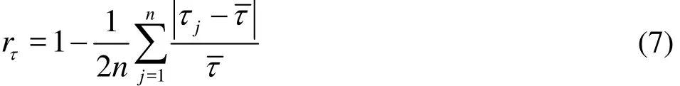
where τ is the shear stress,is the mean shear stress on a surface, anddenotes the uniformity of the shear stress distribution. Figure 8(b) shows the collaborating effects of the blade shapes and the stirring speeds on the facet uniformity of the shear stress on the membrane surface. From an overall perspective, the facet uniformity of the shear stress increases as the vane number increases. Especially at 150 rpm, the facet uniformity of the shear stress declines rapidly from the SV to 3V stirrers, and then it increases from the 3V to 6V stirrers. It is of interest to note that the facet uniformity of the shear stress for the SV stirrer is almost equal to that of the 6V stirrer.That is why the SV stirrer is widely used for biological separations, where the stirrer is only allowed to be operated at low stirring speeds. Although the facet uniformity of the shear stress increases with the increase of the vane number (from the 3V to 6V stirrers), the increase of the stirring speed could accelerate its increase. It is suggested that a high stirring speed should be applied if a high uniform distribution of the shear stress is required quickly.

Fig. 8 Variations of facet average on membrane surface with respect to blade shape
3. Conclusions
This paper focuses on the numerical investigations of the effects of the blade shape on the flow characteristics in a stirred dead-end membrane bioreactor. The RNG -kε model based on the finite volume method is applied to solve the turbulent flows using the software Fluent. The reliability and the feasibility of the proposed numerical model are validated by comparisons with experimental results.The stirred internal flows are numerically simulated.The main findings can be summarized as follows:
(1) The flow structures such as the wake flows and the circulation loops in the stirred flows are well simulated by the constructed 3-D model. A region of low velocities at the membrane center is identified. An increase of the stirring speed is proposed to minimize the area of low velocity.
(2) The flow characteristics induced by the blades with different shapes are compared with each others. It is shown that the increase of the vane number can enhance the mixing effect in the flow domains. However, a circular disk stirrer is not suggested for applications, as it blocks the cylindrical reactor and goes against the formation of vertical circulations.
(3) The collaborating effects of the blade shapes and the stirring speeds are carefully examined by analyzing the results of the facet average and the facet uniformity of the shear stress on the membrane surface. The single vane stirrer is found to be beneficial for biological separations. Results also suggest that the 6V stirrer can provide a uniform distribution of the high shear stress.
However, further studies are still needed for the investigations of multi-phase flows in reactors of more complex geometry.
Acknowledgments
This work was supported by the self-determined project of State Key Laboratory of Advanced Design and Manufacturing for Vehicle Body, Hunan University (Grant No. 51475002), the Fundamental Research Funds for the Central Universities (Hunan University).
猜你喜欢
杂志排行

水动力学研究与进展 B辑的其它文章
- Call For Papers The 3rd International Symposium of Cavitation and Multiphase Flow
- Bubble dynamics and its applications *
- Experimental investigation of flow past a circular cylinder with hydrophobic coating *
- Transient peristaltic diffusion of nanofluids: A model of micropumps in medical engineering *
- High-speed experimental photography of collapsing cavitation bubble between a spherical particle and a rigid wall *
- Flow induced structural vibration and sound radiation of a hydrofoil with a cavity *