Transverse polar navigation method based on virtual sphere model
2018-12-20QINFangjunCHANGLubinTONGLinWANGZhiHUANGChunfuZHAFeng
QIN Fangjun, CHANG Lubin, TONG Lin, WANG Zhi, HUANG Chunfu, ZHA Feng
(Electrical Engineering College, Naval University of Engineering, Wuhan 430033, China)
Abstract: In order to reduce the principle errors caused by the spherical model in traditional transverse polar navigation, the ellipsoidal earth model and complex transverse transformations are often adopted.Based on the fact that the radius of the earth is closely related to its velocity in inertial navigation calculation, a “virtual sphere” model is used to simplify the transverse transformation, and velocity compensations are applied to reduce the principle errors caused by the model simplification.A “virtual sphere” model at the location of the carrier is constructed, which can be regarded as an artificial ball with radius of curvature in Prime Vertical.The attitude, velocity and position differential equations of the improved transverse polar navigation using “virtual sphere” model are deduced.Meanwhile, the dilatation coefficient is adopted to compensate for the carrier’s velocities.Three transverse navigation methods based on the sphere model, the ellipsoid model, and the virtual sphere model respectively are compared.Numerical simulation results show that the proposed method can simplify the complex mechanism of the ellipsoid model method.Its navigation accuracy is superior to that of the traditional sphere model method, and is equivalent to that of the ellipsoid model method.
Key words: inertial navigation; polar region; transverse navigation; virtual sphere
Polar region has become an important scientific research base for human beings.With the rapid development of aviation and navigation, the polar activities of human beings are becoming more frequent, which makes the polar navigation become a hotspot of researching in recent years[1-3].Inertial navigation system (INS) is of great importance, which provides many kinds of navigation parameters by processing outputs of inertial measurements.The greatest advantage of INS is entirely self-contained[4-6].It is not affected by external conditions such as polar geomagnetic changes and solar storms.The advantages of good autonomy make inertial navigation become an important technical means for polar navigation.As the geographical meridians converge rapidly in the polar regions, the traditional inertial navigation methods fail to get positions and orientations in the polar regions.In transverse inertial navigation method for polar navigation, the traditional geographic coordinate system is rotated transversely,which changes the original north and south poles to the equator of the new coordinate system.Based on this idea,the polar region navigation problem is solved theoretically[7].In the 1950s, the “Nautilus” nuclear submarine’s INS used this kind of navigation mechanism to accomplish its missions through the Arctic[7].The traditional transverse navigation uses a spherical model for the earth, which brings advantages of briefness and convenience for transverse rotation of geographic coordinate system.However, the earth is actually an ellipsoid and the corresponding simplification consequentially introduces principle errors for INS.In order to reduce the principle errors induced by the spherical model, some fruitful research work has been done in recent few years.In [8-9],the performances and error characteristics of transverse navigation based on the sphere model are analyzed theoretically.It is pointed out that the principle errors caused by the spherical model are mainly oscillation errors,and damping technology, as applied in traditional INS, is used to suppress the oscillation errors[8].In [10-11], the ellipsoidal Earth model is proposed to address the theoretical error resulting from the inaccurate spherical Earth model.In [10], the radius of transversal meridian and the radius of transversal prime vertical are derived.Since,“latitude” or “longitude” is affected by both “north” velocity and “east” velocity in transversal coordinate system, the individual radius of transversal meridian or the radius of transversal prime vertical is not quite suitable for coupling of transversal navigation.From the view of definition of radii of ellipsoidal earth, radiuses of transversal ellipsoidal earth are derived in details in [11].In [10-11], the WGS-84 earth model is used to determine the elliptic curvature radii.In [12], the CGCS2000 Earth model is applied in the transverse earth coordinate of polar navigation, and the explicit expressions of the curvature radius of the transverse ellipsoid are listed.Although the literature does not present the derivation process, its research ideas is similar to the WGS-84 Earth model for the radius of curvature in detail.Complex ellipsoidal earth model and transverse transformations are essential in [10-12].
In this paper, we abandon the idea of solving complex ellipsoidal radii and propose a new polar navigation method.By constructing a “virtual sphere”model at the local point where the carrier is located, the earth is converted from an ellipsoid to a sphere.So it becomes easier to rotate the coordinate system transversely.Basic equations of the improved transverse polar navigation using “virtual sphere” model are deduced in details, and the dilatation coefficient is compensated for velocities of the carrier.Numerical simulation results show that the proposed method cannot only obviously suppress the oscillation errors from positions, velocities,attitudes and heading in transverse polar navigation method using the spherical model, but also reduce the constant errors from velocities.It can simplify the transformation process of the transverse navigation coordinate system and avoid the complicated transverse navigation mechanism based on the ellipsoid model (WGS-84 or CGCS2000 model).The derivation and solution of complex transverse ellipsoidal radii are all omitted.
1 Transverse navigation coordinate system
In order to address failure problem of the traditional inertial navigation methods in polar regions due to the rapid convergence of meridians in the polar regions, the transverse navigation method can be applied.In the transverse navigation, the traditional geographic coordinate system is transformed into transverse coordinate system.So the original geographical north and south poles become the equator in the new coordinate system,as shown in Fig.1.
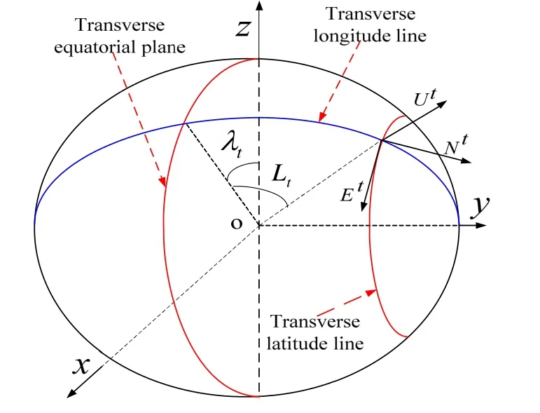
Fig.1 Transverse navigation coordinate system
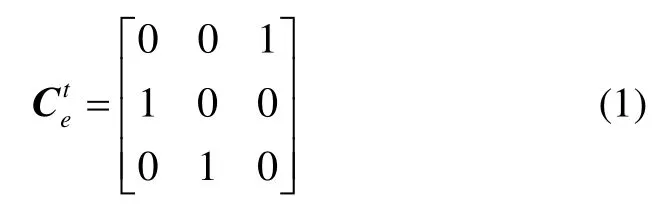
Denote the transverse navigation coordinate system by t.The origin of this coordinate is at the center of the earth O, xtaxis is along the earth rotation axis, ytaxis is along the intersection of meridian (east meridian 0°) plane and equatorial plane, and ztaxis completes the right-handed system.According to Fig.1, the relationship between transverse coordinate systemtand earth coordinate system e is given by
Denote the transverse navigation coordinate system by.Its origin is located at the position of the carrier,axis is along the tangent of transverse latitude circle toward the transverse east.axis is along the tangent of transverse meridian circle toward the transverse north,andaxis is along the normal of sphere toward the zenith.Definition of the transverse latitude and longitude is similar to definition of geometric latitude and longitude.
Let meridional circle, where the prime meridian is located, be the transverse equator, and the original geographic coordinate points [0°, 90°E]and [0°, 90°W]be the new transverse north and south pole, respectively.The transverse meridian is defined as a contour line by crossing the earth with the plane through two transversal poles.Let P be a point on the surface of the earth with heighth.The cross angle between geometric normal and transverse equatorial plane is defined as the transverse latitudetLat point P.The transverse north hemisphere is located in the geographical eastern hemisphere, and the transverse south hemisphere is located in the geographical western hemisphere.Define the initial transverse meridian as the northern hemisphere part of the geographical meridional circle where the geolongitude is 90°E.The cross angle between the transverse meridian surface and the initial transverse meridian is defined as the transverse meridiantλat point P.
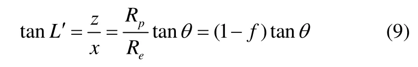
Let a point on the surface of the earth be expressed as (,,)xyzin the earth coordinate systeme.Denote the geography latitude and longitude as (,,)Lhλ, and the transverse latitude and longitude as(Lt,λt,h).The transformation formula between (x,y,z) and(Lt,λt,h) is given by

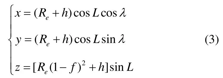
where Reis the elliptical long axle, and fis the elliptical flattening.
The transformation formula between (x,y,z)and(L,λ,h) is given by
According to (2) and (3), the relationship between the geographic coordinate system and transverse navigation coordinate is given by

The aforementioned procedures are the main principle of transverse navigation.For traditional transverse navigation methods, there are two irreconcilable problems.On the one hand, it is easier to rotate a spherical model and develop the corresponding navigation algorithm.However, this will introduce inevitable principle errors due to the fact that the earth is virtual an ellipsoid.On the other hand, the ellipsoid model is used directly to formulate the transverse navigation, and there will be no principle errors for the resulting algorithm.Unfortunately, it is very complex to design the ellipsoid model based transverse navigation algorithm.In the next section, the “virtual sphere” model is designed ingeniously to circumvent the aforementioned problems.
2 Polar transverse navigation method based on“virtual sphere” model
The relationship between the elliptical flatteningfand elliptical long axle Reas well as short axle Rp is given by

Let the coordinates of a point P on the ellipse be:

Through differential operations, it gives


Fig.2 Sketch map of the “virtual sphere”
Since the normal linePOis through the pointPof the ellipse, as shown in Fig.2, the following relationship can be obtained:
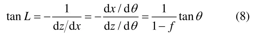
Because
so

Let O′P=Rt′ ,OP=Rt, it gives:

According to the elliptic analytic equation, it can be obtained as

so the following radii can be determined:
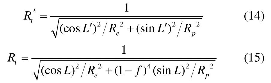
Substituting (4) into (15) gives the “virtual sphere”radius in transverse navigation coordinate system:
Considering the definition of the earth’s meridian circle radiusRM,the “virtual sphere” can be regarded as a man-made sphere with a local P-point with a radius of Prime Vertical Circle.For the meridian circle radius, the“virtual sphere” will bring the dilatation coefficient k,which can be determined by the following formula:

In the geographic coordinate system, the eastward velocity is unchanged, and the northward velocity is multiplied by the dilatation coefficient, which will reduce the error of approximation by “virtual sphere” model.
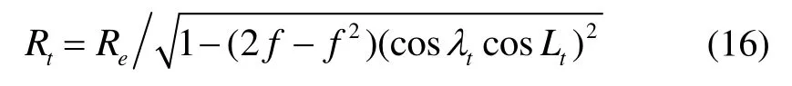
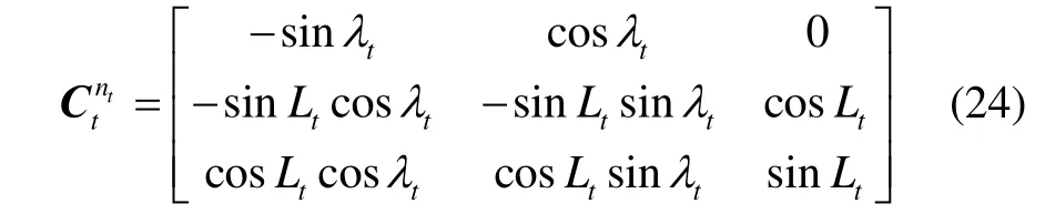
In fact, we should perform velocity compensation in the transverse navigation coordinate system.Relationship between transverse navigation coordinate system ntand geographic coordinate system n can be determined by[11]:

Where β is the angle between ntand n.
We know that:
So velocity compensation in transverse navigation coordinate system is determined by:

Where Vntandare the velocities before and after compensation respectively; K=[100;0 k 0;001];is determined by (18);is the transpose of matrix.
Because the transverse navigation system is still a horizontal coordinate system, equation (21) can be simplified as follows:
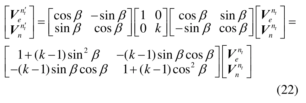
So the matrix calculation in equation (21) will be greatly reduced.
The attitude differential equation of polar transverse navigation based on “virtual sphere” model in the transverse navigation coordinate system ntis given by


In the transverse navigation coordinate system,the velocity differential equation is given by

Since the gravitational vector in the transverse navigation coordinate system points to the center of the earth, thezaxis ofis defined as pointing to the sky.In this respect,
The position update equation is also closely related to the radius of the “virtual sphere”, that is

Eq.(23), (26) and (28) formulate the differential equations of the “virtual sphere” based polar inertial navigation.The main procedures of the proposed “virtual sphere” based polar inertial navigation are illustrated in Fig.3.
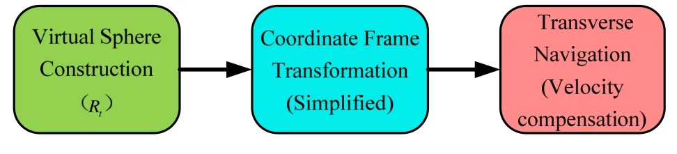
Fig.3 Principle of the “virtual sphere” based polar inertial navigation.
3 Test and analysis
In order to verify the feasibility and effectiveness of the proposed “virtual sphere” based navigation scheme,simulation test is carried out.The trajectory generator is designed as follows: the initial geographical position is(70°N,0°).The geography east speed and north speed are both 6m/s.The geographical heading angle is 45°.The roll angle is set to 5°sin(πt/4)rad, and pitch angle is set to 3°cos(πt/5) rad.The simulation period is 36 h.The traditional spherical model and the “virtual sphere” model are both evaluated under the same conditions.In order to highlight the performance improvement by the model modification, firstly the simulation is carried out without inertial sensors errors.Three transverse navigation methods based on the sphere model, the ellipsoid model[11], and the virtual sphere model respectively are all compared.Curves of the position, velocity and attitude errors are shown in Fig.4-6.The error curves of the virtual sphere model and the error curves of the method of Ref [11]are all overlapped, so that we cannot distinguish.Taking the longitude error and the heading error as examples, the details are compared as shown in Fig.7.It can be seen that the two methods have almost the same accuracy.
Test results are summarized in Table 1, in which the maximum errors (absolute maximum, ABS.MAX) are listed.From Table 1, we know that the sphere model based method and the method of Ref [11]have almost the same accuracy.Both have obvious precision advantages over the sphere model based method.
Taking into account the particularity of polar navigation experiments, Yao et al.[11]has proposed a test method approved by experts in the world.The main idea of [11]is to convert low-latitude measured data to specific high-latitude semi-physical test data after a specific transformation process, and then perform verification experiments for polar region navigation algorithms.Maritime laser gyro Inertial Navigation System data was collected in the laboratory under stationary condition (34.5800°, 114.2428°) for 36 hours.The test data is transformed into high-latitude location(80.00834°, 122.0599°) using methods of [11].Curves of the position, velocity and attitude errors are shown in Fig.8-10.The test results are summarized in Table 2, in which the maximum errors (absolute maximum,ABS.MAX) are listed (constant errors of gyro are about 0.003 (°)/h, and constant errors of accelerometer are about 5×10⁻⁷g).
The hardware and software conditions are as follows:
① Operating system: Windows 7 (32bit);
② CPU: Intel(R) Core(TM) i5-4590;
③ Memory: 4GB;
④ Matlab: R2012a.
The running time of the three methods is shown in Fig.11.

Fig.4a Latitude error (without sensor error)
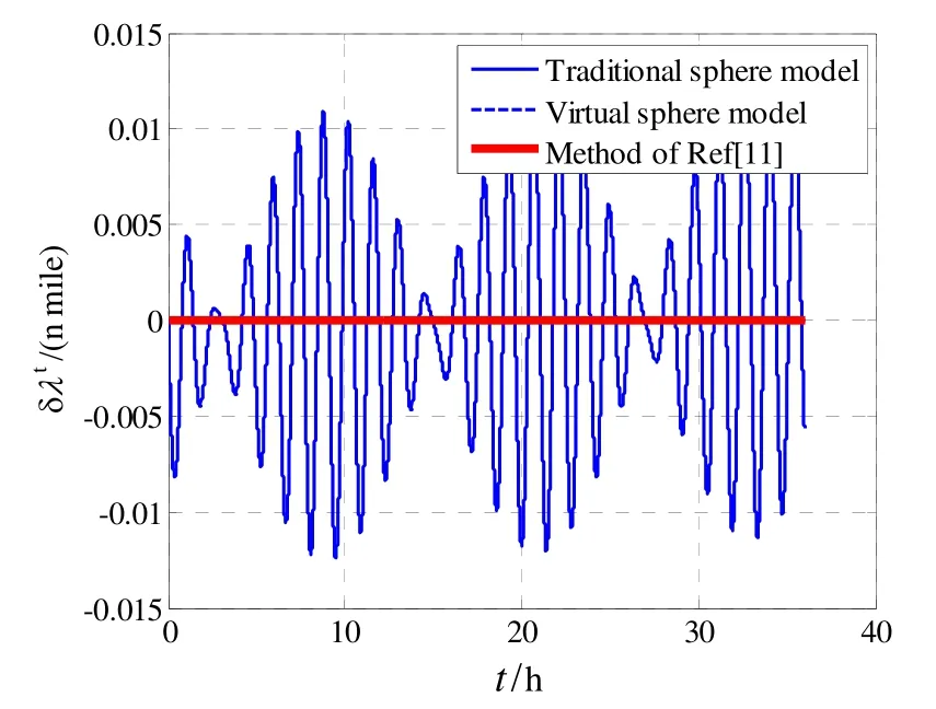
Fig.4b Longitude error (without sensor error)

Fig.5a East velocity error (without sensor error)

Fig.5b North velocity error (without sensor error)

Fig.6a Pitch error (without sensor error)

Fig.6b Roll error (without sensor error)

Fig.6c Heading error (without sensor error)

Fig.7a Longitude error comparison

Fig.7b Heading error comparison

Tab.1 Transverse navigation errors (ABS.MAX) for different models (without sensor error)

Fig.8a Latitude error (with sensor errors)

Fig.8b Longitude error (with sensor errors)

Fig.9a East velocity error (with sensor errors)

Fig.9b North velocity error (with sensor errors)
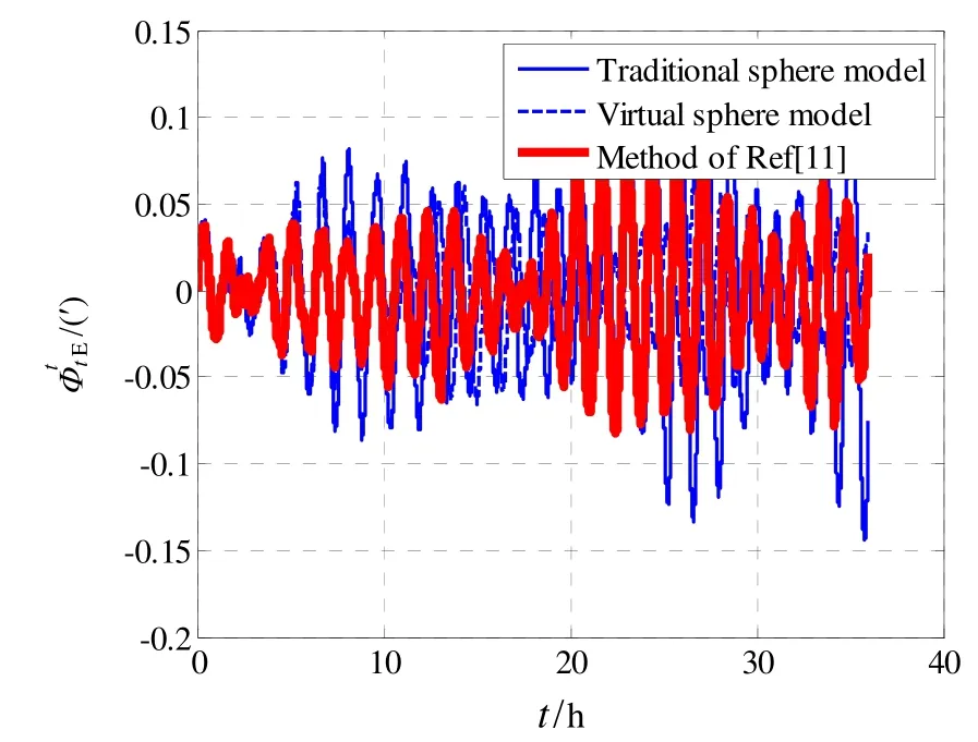
Fig.10a Pitch error (with sensor errors)
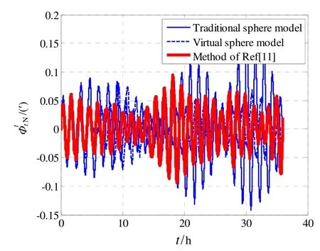
Fig.10b Roll error (with sensor errors)
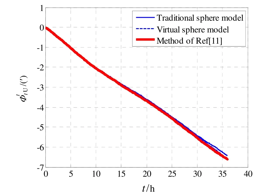
Fig.10c Heading error (with sensor errors)

Tab.2 Transverse navigation errors (ABS.MAX) for different models (with sensor errors)

Fig.11 Run time-consuming
The simulation and test results show that there are obvious principle errors in the traditional transverse navigation using the spherical earth model, which are mainly appeared in form of oscillation errors.The errors will be further deteriorated with the coupling of inertial sensor errors.For a high precision INS, the errors are completely unacceptable.The proposed “virtual sphere”model used in this paper has a significant effect on suppressing the oscillation errors.In addition, the “virtual sphere” model can also significantly reduce the constant errors in the east velocity error and north velocity error(seen from Fig.5a and 5b).The test experiments also show that the accuracy of “virtual sphere” model is better than that of “traditional sphere” model in attitude, speed and position.The error curves of the virtual sphere model and the error curves of the method of Ref [11]are all overlapped.It can also be seen that the two methods have almost the same accuracy from Table 1 and 2.It can be seen from Fig.11 that the “virtual sphere” model based method has almost the same accuracy as the method of Ref [11], but the time consumption is slightly reduced.
4 Conclusion
Polar navigation has become a hotspot of research in recent years.In view of great advantages such as autonomy, inertial navigation has become an important kind of navigation technology in polar region.The transverse navigation method rotates the traditional geographic coordinate system transversely, so that the original geographic north and south poles are transformed into the equator of the new coordinate system, and the technical bottleneck of the traditional inertial navigation in the polar region is theoretically solved.However, the traditional transverse navigation uses a spherical model for the earth.Although the transverse rotation of the coordinate system has brought convenience and briefness, the simplified earth model must introduce obvious principle errors, which are intolerable and unacceptable for high precision INS.In order to reduce the principle errors caused by the spherical model, this paper proposes a new transverse navigation method.By constructing a “virtual sphere”model at the local point where the carrier is located, the coordinate system is rotated easily.Compared with previous similar work, it can simplify the transformation process of the transverse navigation coordinate system and avoid the complicated transverse navigation mechanism based on the ellipsoid model (WGS-84 or CGCS2000 model).The derivation and solution of complex transverse ellipsoidal radii are totally not needed.The method can not only obviously suppress the oscillation errors from positions, velocities, attitudes and heading using spherical model, but also reduce the constant errors from velocities.Simulation and test results demonstrate the validity of the proposed method.