Optimal synthesis of compression refrigeration system using a novel MINLP approach☆
2018-09-28TaoYangYiqingLuoYingjieMaXigangYuan
Tao Yang ,Yiqing Luo ,*,Yingjie Ma ,Xigang Yuan
1 School of Chemical Engineering and Technology,Tianjin University,Tianjin 300072,China
2 State Key Laboratory of Chemical Engineering,Tianjin University,Tianjin 300072,China
Keywords:Optimal design Compression refrigeration system(CRS)Chemical process Process systems Compressor shaft work Mixed Integer Nonlinear Programming(MINLP)
ABSTRACT The optimal design of a compression refrigeration system(CRS)with multiple temperature levels is very important to chemical process industries and also represents considerable challenges in process systems engineering.In this paper,a general methodology for the optimal synthesis of the CRS,which simultaneously integrates CRS and Heat Exchanger Networks(HEN)to minimize the total compressor shaft work consumption based on an MINLP model,has been proposed.The major contribution of this method is in addressing the optimal design of refrigeration cycle with variable refrigeration temperature levels.The method can be used to make major decisions in the CRS design,such as the number of levels,temperature levels,and heat transfer duties.The performance of the developed methodology has been illustrated with a case study of an ethylene CRS in an industrial ethylene plant,and the optimal solution has been examined by rigorous simulations in Aspen Plus to verify its feasibility and consistency.
1.Introduction
In chemical process industry,a low-temperature process has typically complicated integrated networks and intensive energy distributions.Generally,a low-temperature process mainly consists of three parts,i.e.the process,the HEN and the refrigeration system,as shown in Fig.1.All parts in the low-temperature process are highly interacted with each other.As a result,changes in any one of them may exert great influences in the other two parts,and any modification in these three parts would have an impact on the shaft work requirement of the refrigeration system,which leads to an intractable optimization problem[1].Therefore,the interactions should be adequately considered when synthesizing the entire process.
Generally,a refrigeration system occupies the major portion of energy consumption in a low-temperature process[2–4].A typical refrigeration cycle,shown in Fig.2,usually comprises four sections:condensation(I→ II),expansion(II→ III),evaporation(III→ IV)and compression(IV→I).Actually,a refrigeration system may contain several refrigeration cycles working at multiple temperature and pressure levels to satisfy the cooling demands of the low-temperature process.Meanwhile,these multiple temperature levels are also highly coupled,which should be well integrated to minimize compressors' shaft work consumption.
On account of its economic importance,the synthesis of refrigeration systems has been studied for decades.Barnés and King[5]introduced an original concept of CRS synthesis.In their works,they proposed a“two step method”by introducing an initial node-oriented network to synthetize an optimal CRS independent of the heat-recovery networks.With the topological relationship and heuristic rules,Cheng and Mah[6]developed an interactive model to carry out a CRS synthesis by predetermining levels and simplifying calculation of shaft work,and they summarized that the selected refrigerant should be determined by the operating temperature range of the refrigerant and the target temperature of the process streams.Linnhoff and Dhole[7]developed an exergy-based method to estimate shaft work consumption in the Exergy Grand Composite Curve(EGCC),where the change in shaft work requirement from refrigeration system could be related to the change of area on the EGCC.Based on the exergy-based method,Zhang and Xu[8]optimized CRS with considering the stage-wise subcoolers,but the HEN design was not included.Luo et al.[9]studied the optimization of refrigeration system by targeting the actual shaft work which was estimated through exergy analysis.However,in their works,the estimations of shaft work or the ignorance of interrelation among refrigeration levels were too rough to guarantee the optimization.Furthermore,it was difficult to denote the requirement change in shaftwork consumption as a result of constant exergy efficiency or involved design options.

Fig.1.The interactions among process,HEN and refrigeration system.Lee,Guangchung.“Optimal design and anaylysis of refrigeration systems for low temperature processes”,University of Manchester,2001).
Provided a collection of discrete intermediate temperature levels as candidates,Shelton and Grossmann[10]proposed an early Mixed Integer Linear Programming(MILP)model to minimize refrigeration systems cost based on the superstructure.Colmenares and Seider[11]proposed a Nonlinear Programming(NLP)method for refrigeration system to integrate with the chemical process with the heat pumps as participation.Vaidyaraman and Maranas[12]further attained the optimal structure of the CRS and the optimal refrigerant at the same time by accommodating multi-refrigerant and multi-level refrigeration.However,the effects of the sub-coolers on reducing the expansion ratios of throttling process and improving the efficiency of the refrigeration cycle were neglected.In fact,the optimal refrigeration levels matter a lot in determining the final configuration of CRS and HEN.In order to obtain the optimal refrigeration levels,Wu[13]discretized the whole temperature range as several intervals,which involved large numbers of binary variables denoting the potentiallevels,to search optimal levels and design of CRS.Dinh et al.[14]proposed an exergy-based MILP model to deal with the synthesis of CRS by pre-determination of available temperature levels.However,the pre-determined discrete refrigeration levels in the preprocessing stage could not guarantee proper matches among temperature levels and reduce exergy losses.Actually,for the coupled interactions among levels,the number of levels,level temperature and adaptive heat duties are all supposed to be variables,and simultaneously optimized to adjust to the conditions of the process.
Wu and Zhu[15]introduced an MINLP approach to integrate CRS and HEN,in which the temperature levels were continuous variables by introducing “extended cascades”,and empirical rules greatly guided it to reduce binary variables.However,the model was so large and complex that the feasible solution heavily depended on the initial values.Chen[16]proposed an MINLP model to solve the CRS synthesis with continuous operating temperature,however,in his model,the integration opportunities within the CRS cycle were partially ignored.Chuang[17]further extended the superstructure of Vaidyaraman and Maranas[12]and Chen[16],and developed a mathematical model to obtain the optimal CRS in a continuous temperature manner without considering the coexistence of multiple process heat streams and process cold streams.
With the achievements in mind,we can conclude that the conventional methods for refrigeration system synthesis heavily depended on empirical rules to pre-determine temperature levels or ignore the complicated integration.In these method,the HEN and refrigeration system were mostly designed individually:the HEN was designed to satisfy the refrigeration duties of each pre-determined temperature level,then the refrigeration system was designed to meet the requirements.However,only a few researchers have comprehensively considered or dealt with the synthesis of refrigeration system which simultaneously integrates HEN and refrigeration system with variable temperature levels.This paper focused on the synthesis of multiple-level CRS,which not only satisfied the demands with a larger temperature range,but led to an energy-saving benefit by means of multi-level expansions[18],and then proposed a novel MINLP approach for synthesis of CRS with variable refrigeration temperature levels.In this study,the superstructure was constructed,the temperature levels,the number of temperature levels as well as the heat duties were set as variable to search optimization,and the “extended transshipment model”was introduced for energy calculation.The overall synthesis procedures could be easily followed,and the optimal results could also be supported by Aspen Plus.
2.Problem Statements
2.1.Given information
i)A chosen refrigerant with corresponding thermodynamic properties;and
ii)nHhot process streams to be cooled and nLcold process stream to be heated.The initial and target temperatures,compositions,heating or cooling demands and flow rates of process streams are also known.
2.2.Assumptions
i)The refrigerant leaves condenser as saturated liquid and exits evaporators as saturated vapor;
ii)In the system,the enthalpy changes within the temperature intervals are calculated using an average heat capacity CP,and CPmay be different for different levels and intervals;and
iii)The pressure drop in the heat exchangers is neglected in this work.
2.3.Information to be determined
i)The detailed structure of whole refrigeration system including the refrigeration components connections among levels;
ii)The number of temperature levels,the specific temperature of each level in the optimal CRS;
iii)The compressor shaft work;and
iv)The configuration of flow rate,heat duties in each exchangers of each level in the optimal CRS.
3.MINLP Modeling Development
3.1.The superstructure of CRS

Fig.3.The superstructure of the multi-level CRS of a single refrigerant.
The developed superstructure sketch of multi-level CRS,which covers all possible connections among higher-and lower-temperature levels,can be shown in Fig.3.It is worth noting that the cold source provided by the plant,if it exists,can be employed to subcool the refrigerant through sub-coolers to totally or partly replace the throttle valve,which naturally reduces the exergy loss and improves the efficiency of utilization,the fact can be illustrated with a retrofit case by Zhang et al.[19].
This superstructure considers three general scenarios on how saturated refrigerant liquid from a condenser or an economizer leaving from a chosen level can be directed to the next level(s):i) flows to the next evaporation section by passing a subcooler or a throttle valve;ii)bypasses the next evaporation section(s)and directly flows to evaporation section(s)of even lower-pressure levels;iii)simultaneously passes a subcooler and a throttle valve by splitting the refrigerant liquid from the condenser or an economizer.The vapor streams from an economizer can be compressed to either or multiple high-temperature levels.
Based on the superstructure,all the model equations covering the mass and energy balance of each spilt cycle,the equality and inequality constraints with all possibilities will be formulated and solved.For the needs from process,the thermodynamic data inputs for the mathematic model can be obtained through the rigorous steady-state simulations.
3.2.Objective function
The goal is to minimize the total shaft work of all existing compressors,which can be calculated with Eq.(1).

Specific shaft work between two existing levels can be calculated through the polytropic compression model[20]as Eqs.(2)–(4)show.

where Tot W is the total shaft work,and it equals the sum of compressor shaft work in all existing levels.TCImis the inlet temperature of the compressor at level m;Cp∗is the heat capacity of superheated vapor through the compressors;Wm,jis the shaft work calculation equation from level m to level j;mTand kTrespectively represent the polytropic exponent and adiabatic exponent of superheated vapor during the compression process;Zmis the vapor average compression factor of level m;R is the general gas constant;a is the first parameter of the fitted relation between saturated pressure and saturated temperature of vapor and b is the second parameter of the fitted relation between saturated pressure and saturated temperature of vapor.
3.3.Mass balance equations and constraints
The mass balance equations and constraints can be formulated according to the connections reflected in the superstructure,which are listed in Sections 3.3.1–3.3.4.
3.3.1.Compression
In each cycle,the mass balance equations are all formulated around the compressor,and the constraints can also be added.The overall model equations can be listed as Eqs.(5)–(11):

where FGmrepresents the mass flow rate of the saturated vapor out from the flash drum at m-th level;FCi,mis the mass flow rate from the outlet of compressor at the i-th level to the compressor inlet of m-th level,similarly,FCm,jdenotes the connections from m-th level to j-th level;Tmis the refrigeration temperature to be optimized at the m-th level,and its existence is also related with the binary variable ym.Γ is a big enough number,which guarantees the existence of the variables.Yi,mis a binary variable,which denotes the existence of compressor connection between the i-th level and the m-th level,and Ym,jis also a binary variable with the similar meaning,indicating the connections between m-th level and j-th level of compressor.
We define the temperature when the liquid refrigerant flowed out from condenser as the 0-th level,then Eq.(12)satisfies:

Besides,for an optimization problem,Eq.(13)limits the maximum alterative temperature levels.

3.3.2.Condensation
The superheated refrigerant out from the compressor at0-th level to the condenser is cooled by the other refrigerants,such as propylene or cooling water.Eq.(14)expresses the mass balance of the condenser.

where,F0is the total initial flow rate in the CRS,which equals to the total initial feeds(represented by FL0)to lower levels.
3.3.3.Expansion and sub-cooling
What can be the reason for such a crowd close by the pigsty? said theEmperor, who happened just then to step out on the balcony; he rubbed hiseyes, and put on his spectacles. They are the ladies of the court; I must godown and see what they are about! So he pulled up his slippers at the heel,for he had trodden them down.
The saturated liquid refrigerant from higher-temperature levels is about to reach the lower-temperature levels by passing through subcoolers(if exists)or throttle valves.It should be referred that the existence of either component and the coexistence of both components are all permitted.The model equations and constraints of this section are expressed in Eqs.(15)–(18).

where,FSmis the total refrigerant flow rate of the m-th level,which enters the evaporation section;FSCj,mand FVj,mrespectively represent the flow rate passing through the sub-coolers and throttle valves from the higher level j to the lower level m;FVGj,mis the flow rate of vapor refrigerant due to expansion by passing through the throttle valves connecting the j-th level and the m-th level.Correspondingly,the related vapor fraction can be expressed in vfj,m.
3.3.4.Evaporation and flashing
Refrigerant evaporates by absorbing heat from the heat resource supplied by plant.Then the refrigerant enters the flash drum to achieve separation of vapor and liquid as branches or feeds to other sections.The equations and constraints can be described with Eqs.(19)–(21):

where FEmrepresents the flow rate produced due to evaporation at the mth level;FLmis the flow rate of the liquid refrigerant out from the flash drum,meanwhile,it also acts as the feed of the lower-temperature levels.FSCm,iis the refrigerant flow rate that can satisfy the heat duties of the process streams from the m-th level to i-th level,and the FVm,iexactly is the parts of refrigerant passing through the throttle valves.
In addition,in order to guarantee a closed-loop cycle in the CRS system,the constraints Eq.(22)must be added:

3.4.Energy balance equations and constraints
The energy balance should be conducted to attain the inlet and outlet temperature of all refrigeration components in the CRS.Besides meeting the cooling demands by implementing evaporators,the major heat integration opportunities in this CRS are to satisfy heat demands by implementing sub-coolers.Therefore,condenser energy performance is not included in this CRS modeling embedded HEN.The main calculations of energy balance can be focused on compression,sub-cooling and evaporation and it should be noted the reference temperature must be specified when it comes to the enthalpy calculations of refrigerant.In this study,the calculation of enthalpy will be conducted based on the enthalpy of the M-th temperature level.
3.4.1.Compression
The equations and constraints of energy balance around each compressor in all levels are developed with the assumption of the constant heat capacity for vapor streams as Eqs.(23)and(24):

3.4.2.Sub-cooling and evaporation
Papoulias and Grossmann[21]introduced the conventional“transshipment model”to interlink heat recovery networks and chemical process.In this Linear Programming(LP)model,the temperature intervals divided by the process streams were all pre-determined and fixed to conduct energy dispatches.However,in this paper,due to the existence of partial uncertain refrigeration levels,the interval temperatures cannot be totally fixed and the conventional“transshipment model”failed to describe the heat transportation problems within an un fixed interval.For the reasons mentioned,this research extended the original“transshipment model”as a nonlinear “extended transshipment model”to include known temperatures and partial uncertain temperatures for the energy balances and distributions through the HEN.
The operation can be followed according to the procedures described below.
i)The temperature interval based on the process streams
We define a set TP={n|1,2,…N}as a collection of interval temperature divided by process streams,and the values of interval temperature TPn(1≤n≤N)should cover all the initial temperatures and the highest/lowest temperature of the process streams.All the interval temperatures are listed in a decreasing order(i.e.TP1≥TPm≥TPm+1≥TPN).In this refrigeration system,the utilities are acted as by the refrigerant flowing through sub-coolers and evaporators.Therefore,the refrigeration temperature levels should also be covered in the set.
ii)The setting of potential refrigeration temperature level
A set of potential refrigeration temperature levels TM={m|0,…,M}was defined to represent all potential temperature levels.In this set,the total potential number of levels(M)was also a variable to be optimized.Every potential temperature level is associated with a binary variable:y0,y1,…,yM,and it is present when the value is 1,otherwise 0.Within the temperature interval m(TPm→TPm+1,1≤m≤N−1),a temperature Tmcan be inserted as potential refrigeration level(if the temperature range of interval m is less than minimum approach temperature preset,and no phase change of process streams happens,the insertion can be neglected).What's more,the newly inserted temperature level Tmshould satisfy the bound constraint:TPm>Tm≥TPm+1.In fact,the actual temperature range of the refrigeration system is larger than the temperature range that process streams can cover.Thus,a maximal upper bound T0and a minimal lower bound TMare necessary to be added as actual refrigeration level with the constraints[15]:TP1+δ>T0≥TP1,TPN>TM≥TB,where δ is an engineering determined positive value,and TBrepresents the saturated temperature at atmospheric pressure.The descriptions can be shown in Fig.4.
iii)The “extended transshipment model”

Fig.4.The division of temperature intervals and setting of potential refrigeration levels.
Here,we can also define a set TV={s|1,2,…,S},which covers temperatures of both process streams and potential refrigeration levels.The adjacent temperatures can determine a range,in which the energy balance equations can be applied to describe heat distribution in each interval formulated by Eqs.(25)and(26).

where Rsis the residual heat leaving the interval s.QmE,calculated with Eq.(26),is the total heat duties in the evaporators at the level m.Here,we define a set PH={h|1,2,…,H}and a set PL={l|1,2,…,L}to represent the collection of the heat process streams and cold process streams respectively.Then Qhs,hrepresents the duties exchanged in the interval s from the hot process stream h,and similarly,QCs,lrepresents the duties exchanged in interval s from the process cold stream l.
From what has been discussed above,the M-th level always exists,namely Eq.(27)satisfies:

During the refrigeration process,the refrigerant vaporized in the evaporators and subcooled in the sub-coolers can be regarded as the cold utilities to supply cold sources and hot utilities to supply hot sources respectively.On the grounds that,the system can be treated as a refrigeration cycle without utilities,correspondingly no heat of initial supply and final residue,and the Eqs.(28)and(29)should be met to guarantee it.Additionally,the second law of thermodynamics should be followed in the form Eq.(30).

3.5.Model summation
The MINLP model formulation of the methodology for the optimal synthesis of the CRS is given below,which can be developed and solved in GAMS[22]efficiently.

m=1 Wm,j ∀m,j∈TM (1)s.t.Mass balance (5),(14)–(16),(19)–(22)Energy balance (23)–(26)Equality constraints (2)–(4),(10)–(12),(27)–(29)Inequality constraints (6)–(9),(13),(17),(18),(30)min TotW= ∑m−1∑M j=0
4.Case Study
A case study about retrofitting an ethylene CRS in an existing ethylene plant can be given to demonstrate the proposed process synthesis method.
4.1.The original ethylene CRS
4.1.1.Flowsheet and Exergy–Temperature chart
The original flowsheet of an ethylene CRS with three levels is given in Fig.5(a).This process was rigorously simulated in Aspen Plus to obtain exergy data of every refrigerant stream,the corresponding Exergy–Temperature chart[14]of the base case could be depicted in Fig.5(b),we could see that there existed much exergy loss at the throttle valves through expansion.Through the proposed method,the number of the refrigeration levels,the temperature of each level,the heat duties in each level,and the implementation of sub-cooler are all optimized to obtain the configuration with less shaftwork consumption and exergy loss.

Fig.5.(a)The flowsheet of original ethylene CRS and(b)the Exergy–Temperature chart of original ethylene CRS.
4.1.2.The information of process streams
The related process stream data were collected and listed in Table 1.

Table 1 The data of the process streams
4.2.The results comparison
Based on the proposed method and relevant process stream data,the CRS was able to be synthetized to satisfy the requirements,and the retrofitted design can be presented in Fig.6(a),with the corresponding Exergy–Temperature chart shown in Fig.6(b).
The optimization results provided a primary refrigeration system structure with 3 compressors linking condenser and other optimized levels.The total compression shaft work was 4.55 MW,which saw a decrease of about 8.08%.This proved the optimal retrofit was feasible and effective(Table 2).
From the comparison in Table 3,we can see that after retrofit,there was a lot of reduction in exergy loss,part of which was converted to available exergy by the means of setting sub-coolers at appropriate locations reasonably(Fig.6(b)showed).

Table 2 The comparison of exergy loss between the original system and the present optimized system

Table 3 The comparison of exergy loss between the original system and the present optimized system
According to above comparison results,the optimized system was more energy-saving.Moreover,its feasibility was validated by Aspen Plus simulation.In this paper,the detailed HEN design was not generated through the proposed synthesis method.However,with the concept of“shaft work target”,a HEN match with process streams and CRS can be designed easily according to other practical methods while treating it as an independent problem[23,24].

Fig.6.(a)The structure of optimized ethylene CRS and(b)the Exergy–Temperature chart of optimized ethylene CRS.
5.Conclusions and Prospects
This paper presented a systematic method for optimal synthesis of CRS with variable temperature levels by using a novel MINLP approach.In this method,the model is based on the establishment of a superstructure of corresponding refrigeration system,and an“extended transshipment model”is introduced for HEN synthesis.Instead of predetermining the discrete temperature levels in this method,the number of refrigeration temperature levels,the temperature of each level and the heat duties of each level were all set as variables to be optimized,and the shaft works were obtained by calculations rather than estimations.Through an industrial case,the methodology has proved effective with a total shaft work reduction 8.08%,which was supported by rigorous simulation in Aspen Plus.As was shown,this methodology not only provided an effective synthesis procedure,but it allowed greater flexibility by enabling the detailed consideration of complex integration,the handling of split cycles with larger temperature range,and the generation of optimal solutions involving variable refrigeration levels as well as adaptive demands.
However,there remain several problems to be further researched.First,during the conceptual design of refrigeration superstructure,there is an assumption that the outlet temperatures of the refrigerant passing through the sub-coolers and throttle valves were equal,which is difficult to be fulfilled in the practical operations and will be further improved.Second,this paper used total shaft work as an objective function and ignored the equipment cost.However,for a more competitive design,total annual cost(TAC)should be minimized,which will be addressed in our future work.Furthermore,the refrigeration system synthesis discussed in this paper involved only a single refrigerant.In the future,based on the proposed model,the CRS adopting multiple or mixed refrigerants can be optimized to explore a more economical and energy-saving design.
Nomenclature

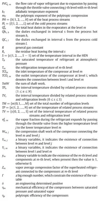
Superscripts
Subscripts

杂志排行

Chinese Journal of Chemical Engineering的其它文章
- Feature selection for chemical process fault diagnosis by artificial immune systems☆
- A decision tree based decomposition method for oil refinery scheduling☆
- Synthesis of refrigeration system based on generalized disjunctive programming model☆
- Control structure comparison for three-product Petlyuk column☆
- Process optimization of an industrial acetic acid dehydration progress via heterogeneous azeotropic distillation☆
- Synthesis of indirect work exchange networks considering both isothermal and adiabatic process together with exergy analysis☆