Synthesis of refrigeration system based on generalized disjunctive programming model☆
2018-09-28DanleiChenXueMaYiqingLuoYingjieMaXigangYuan
Danlei Chen ,Xue Ma ,Yiqing Luo *,Yingjie Ma Xigang Yuan 2
1 School of Chemical Engineering and Technology,Tianjin University,Tianjin 300072,China
2 State Key Laboratory of Chemical Engineering,Tianjin University,Tianjin 300072,China
Keywords:Refrigeration system Process synthesis Generalized Disjunctive Programming(GDP)Mixed Integer Nonlinear Programming(MINLP)
ABSTRACT Refrigeration system holds an important role in process industries.The optimal synthesis cannot only reduce the energy consumption,but also save the production costs.In this study,a general methodology is developed for the optimal design of refrigeration cycle and heat exchanger network(HEN)simultaneously.Taking the heat integration between the external heat sources/sinks and the refrigeration cycle into consideration,a superstructure with sub-coolers is developed.Through defining logical variables that indicate the relative temperature positions of refrigerant streams after sub-coolers,the synthesis is formulated as a Generalized Disjunctive Programming(GDP)problem based on LP transshipment model,with the target of minimizing the total compressor shaft work in the refrigeration system.The GDP model is then reformulated as a Mixed Integer Nonlinear Programming(MINLP)problem with the aid of binary variables and Big-M Constraint Method.The efficacy of the process synthesis model is demonstrated by a case study of ethylene refrigeration system.The result shows that the optimization can significantly reduce the exergy loss as well as the total compression shaft work.
1.Introduction
Refrigeration system is widely used to provide cold utilities for petrochemical processes.So it holds an important role in process industries.Generally speaking,it works by obtaining heats from low temperature sources and passing them to high-temperature sinks,with the compression work consumed.The Fig.1 shows a diagram of a simple refrigeration loop,composed of four components:condenser,expansion valve,evaporator and compressor.The liquid refrigerant gets heat from a process stream in the evaporator section and delivers it to other process streams through the condenser.In this cycle,the refrigerant can be repeatedly compressed,condensed,expanded and evaporated to achieve the cooling requirement continuously.In addition,multiple pressure levels can simultaneously exist in the refrigeration system,according to the specific requirements.The optimization of the refrigeration system,which is a large energy consumer,can reduce the energy loss and further save the final production cost.Therefore,this issue has been widely studied in decades.
Barnés and King[1]developed one of the earlier models of a refrigeration system.They used heuristics and dynamic programming simultaneously to increase intermediate pressure stages.Cheng and Math[2]improved the model,and extended the system to mixed refrigerant cycle.Because of the significant dependence on heuristics,these methods could not guarantee the solution optimality for complicated refrigeration system.Under this circumstance,the mathematical programming method was used by Shelton and Grossmann[3],who put forward a mixed-integer linear programming(MILP)method based on the superstructure of the refrigeration system.From then on,a large number of studies were carried out on this foundation and more reasonable superstructures were established[4–7].However,the research on the optimization of refrigeration system with multitemperature levels was still lacking.
On this basis,Zhang and Xu[8]proposed a general methodology for the optimal process synthesis of a cascade refrigeration system(CRS)with multiple temperature levels and multiple refrigerants,based on exergy analysis.Luo,Feng,Sun and Yuan[9]presented a systematic approach for optimizing low-temperature system through mathematical method and exergy analysis.Then,Zhang,Xu and Dinh[10]simplified the superstructure of CRS and presented an MILP method.They assumed that the refrigerant from level m″to level m flowed through either a sub-cooler or an expansion valve.However,the possibility of refrigerant passing through an expansion valve after a sub-cooler was ignored.Hence,the simplified model was impractical and still defective which was unable to achieve the optimization objective.

Fig.1.Diagram of a simple refrigeration loop.
In this paper,a more complete superstructure is proposed.In order to make up for the previous deficiencies,the third situation,in which the refrigerant from level m″will pass through an expansion valve after a sub-cooler to level m,is taken into consideration.Thus,a continuous variable is introduced to the model because of the unknown temperature after the sub-cooler,and branching selections are generated.So the GDP model is established to solve the segmentation problem caused by the indetermination of the temperature in a refrigeration system and is then reformulated as MINLP model by using binary variables and Big-M Constraint Method.An appropriate refrigerant and a set of process streams with known initial and targeted temperatures as well as their heating and cooling demands are given in this problem.The target is to obtain an optimal vapor-compression refrigeration system with minimizing total compressor shaft work.According to the objective,a superstructure is developed to determine the optimal pressure levels,the existence and the outlet temperature of inter-stage sub-coolers,the total flow rate of the refrigeration system,as well as the basic HEN structure.The assumptions of the problem are summed up as follows:
1.An average heat capacity Cpis used within the temperature interval;
2.The refrigerant leaves evaporators as saturated vapor and leaves condenser and sub-coolers as saturated liquid.
2.MINLP Model
2.1.Process superstructure development
The superstructure sketch in Fig.2 shows all reasonable connections among higher and lower-pressure levels.The refrigerant from level m″(which can be any level higher than m) flows to level m by passing a sub-cooling section.It contains three general scenarios:(1)the outlet temperature of the sub-cooler from level m″equals to the temperature of level m so that only the sub-cooler exists;(2)the outlet temperature of the sub-cooler from level m″equals to the temperature of level m″;that is to say there are no sub-coolers between the two levels but only expansion valve;(3)the outlet temperature of sub-coolers from level m″is located inside the temperature interval of level m″and m so that both sub-cooler and expansion valve are existing.Hence,the refrigerant continues passing through the evaporation section of mthas a vapor–liquid mixture and goes through phase separation in the adiabatic flash drum.The saturated vapor from flash drum together with the superheated vapor from the lower-pressure level is compressed to a higher-level by entering the compressor of level m″,and the saturated liquid from flash drum flows to the lower level m′.

Fig.2.The superstructure of a single-component multilevel refrigeration system
According to the superstructure shown in Fig.2,an MINLP model including material and energy balance of each unit operation with equality and inequality constraints by considering all possibilities will be developed and solved.
2.2.MINLP model development
2.2.1.Mass balance equations
The MINLP model consists of five parts,i.e.mass balance,energy balance,equality constraints,inequality constraints and objective function.The GDP model is used because of the branching selections existing in the HEN transshipment model.
The mass balance of the compressors is represented by Eq.(1):

where fgmis the mass flow rate of the saturated vapor from flash drum of level m;fcm′,mis the mass flow rate of the stream into the compressor connecting the level m′and m;fcm,m″is the mass flow rate of the stream out of the compressor connecting the level m and m″.Note that the set SM={m|0,…,M}is the combination of all possible pressure levels;level m″is upper than m while m′is the lower one.
The refrigerant flow from a higher-pressure level to a lower one passes through the sub-coolers and expansion valves.Mass balance for all possible scenarios about whether a sub-cooler exists or not between any two levels is shown in the Eqs.(2)and(3):

where fxmis the inlet mass flow rate of flash drum at level m;fscm″,mand fscm,m′are mass flow rates of refrigerant through the sub-coolers or/and expansion valves entering and leaving level m;femis the mass flow rate of the saturated liquid from flash drum of level m.
If the expansion valve exists between the two chosen levels,fvm,the amount of vapor generated by the valve at mthpressure level,can be calculated as follows:
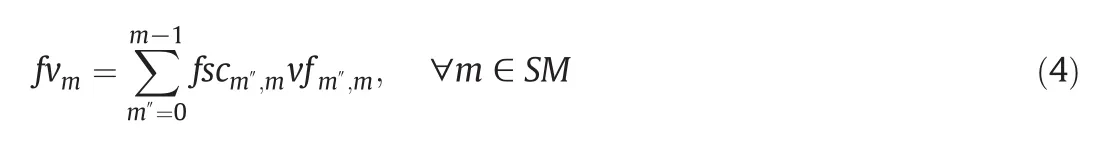
where vfm″,mis the vapor fraction of refrigerant leaving the valve.As mentioned earlier,the refrigerant flows through the valve under the isenthalpic condition,so according to the mass balance and energy balance,the vfm″,mcan be calculated as follows:

where HFm″,mis the mass specific enthalpy of the stream atthe entrance of the expansion value.Meanwhile,HVmand HLmindicate gas specific enthalpy and liquid specific enthalpy at the outlet of the expansion respectively,as shown in Fig.3.


Fig.3.The sketch of the sub-cooler and valve section.
HFm″,mcan be expressed by its corresponding Tscm″,m,which is the temperature of the refrigerant leaving the sub-cooler from level m″to level m.Here,the values of HVmand HLmcan be obtained from the thermodynamic database.
Eqs.(7)and(8)represent mass balance of the saturated vapor and liquid streams leaving the flash drum at level m,where fvemis the mass flow rate of saturated vapor generated by the evaporating section at mthlevel.

2.2.2.Energy balance equations
In the low temperature separation system,the heat exchanger network and the refrigeration system are strongly interacted.The heat exchanger network determines the minimum demand for cold utility.However,the levels of refrigeration system and cooling amount generated by the refrigerant directly affect the design of HEN.Therefore,the synthesis of the refrigeration system must take the design of HEN into consideration to obtain the optimal structure.In order to solve this problem,this paper uses the HEN synthesis transshipment model to calculate the amount of refrigerant in the refrigeration system.Combining transport model with the refrigeration system superstructure,the minimum shaft work of the compressors,and the simple structure of HEN and refrigeration system could be obtained finally.
In a multi-stage refrigeration system,the cold amount required for the condenser at the 0th level is generally provided by other refrigeration systems and is not under consideration in this model.
To construct the HEN synthesis transshipment model, firstly the temperature intervals are divided,which are expressed as SJ={j|0,……,J}.The temperature ranges include the following three cases:(1)the inlet temperatures of all the process streams;(2)the maximum or minimum outlet temperatures(3)the inlet temperatures of the utility flows.In addition,the minimum temperature approach in the HEN is 2°C.Besides,for the sake of calculation,the temperature rise of the isothermal evaporator is set to 0.2°C.Then,according to the HEN synthesis transshipment model proposed by Papoulias and Grossmann[11],for each heat interval,as shown in Fig.4,the heat balance relationship of the jthtemperature interval is established in Eq.(9).

In this equation,Rj-1,and Rjare the remaining heat at the(j-1)thand jthtemperature intervals,respectively.UHjand UCjare the heat provided or removed by the hot and cold utilities,respectively.Similarly,QHjand QCjare the heat provided or removed by the process streams.

Fig.4.Diagrammatic sketch of the heat exchange in j th interval.
According to the superstructure,the HEN synthesis transshipment model can be expressed as follows:

Here,Rjand Rj-1have the same meanings as in Eq.(7).Qtj,m″,m,whose detailed calculation method will be introduced in Section 2.2.3,means the heat duty from sub-coolers of m″-level to the m-level,in temperature interval j;and Qxmindicates the duty of the cold side offered by evaporators at the m-level for the temperature corresponding interval.zj,m″,mand xij,mare both binary variables,which determine whether the temperature of sub-cooling sections and the evaporating sections cross the j-th interval.Variables will be given as known quantities in specific problem,with the exception of
Rj-1,Rj,Qtj,m″,mand Qxm.It should be noted that Qxmcan be calculated by the mass flow rate of vapor produced at the m-th evaporator,which is represented as fvem,and the latent heat of vaporization of refrigerant under the m-th pressure,shown as Δhrm.Under the hypothesis of ideal gas,Δhrmcan be obtained from the thermodynamic database.

2.2.3.Inequality constraints based on GDP method
Based on the super structure proposed in Fig.2,the refrigerant from level m″passes through the expansion valve after the sub-cooler to level m.The outlet temperature of the sub-cooler is a continuous variable,which can be represented as Tscm″,m.The heat duty Qtj,m″,mcan be regarded as a segmentation function with respect to Tscm″,m.Hence,the GDP model[12–15]is introduced to solve the branching selections.The relative position of the inlet and outlet temperatures of sub-coolers to temperature interval j is shown in Fig.5,where Tm″represents temperature of refrigerant before the sub-cooler from level m″to level m,and Tscm″,mindicates the outlet temperature;Tej-1and Tejare the upper and lower boundaries of the interval j,respectively.Besides,Tscm″,mis a continuous variable ranging from Tmto Tm″.


Fig.5.Relative position of streams in sub-cooling section to temperature j.
There are six position relationships in Fig.5.Since the values of Tm″,Tej-1and Tejare known,the last three can be represented by the binary variables zj,m″,m.Based on this,the GDP model can be established.In order to show the relative position relationships,the logical variables are defined as below:

GDP expressions are as follows:

There are three constraints in the equation,and only one constraint will take effect,while the rest do not work.Each logical variable should satisfy the constraint(16):

Through the binary variables,the GDP expression can be reformulated into MINLP model by means of the Big-M method[16].The equality constraints in GDP can be replaced by two inequality constraints.

(a)When Tscm″,mis smaller than Tej,Y1jis True,so y1j,m″,mequals one.The heat quantity provided by refrigerants at sub-cooling section can be calculated by the inequality equations.y1j,m″,m,y2j,m″,mand y3j,m″,mare binary variables,and have the same meanings with the relative logical variables Y1j,Y2jand Y3j.M1and M2are large-enough numbers.

(b)When Tscm″,mis between Tejand Tej-1,Y2jis True,so y2j,m″,mequals one.Then Qtj,m″,mcan be expressed by constraints(19):

(c)When Tscm″,mis bigger than Tej-1,Y3jis True,so y3j,m″,mequalsone,and the inequalities change to constraints(20):

Only one of the three sets of constraints will come into force in interval j.Besides,when yj,m″,mis equal to zero,the relative Qtj,m″,malso equals zero.Therefore,the logical constraints(21)–(24)are added:

Accordingly,heat provided by refrigerants through sub-coolers from level m″to level m can be calculated by Eq.(26).

2.2.4.Objective function
In this paper,the target of the mathematical model is minimizing the total shaft power of compressors.The objective model is shown in Eq.(27),where W is the total shaft power of compressors,and Wm′,mindicates shaft work of compressors between level m′and m.

The method of calculating Wm′,mis given in Eq.(28),where wfm′,mrepresents the specific shaft work of compressors from level m′to level m.It can be obtained by rigorous simulation,when compressor efficiency is supposed to be 72%.

2.2.5.Equality constraint
The binary variable ymvalues equal one when the pressure of mthlevel exists;otherwise it equals zero.The condenser in the refrigeration system is considered to be the highest pressure level in the whole system at level 0.Since the 0-stage condenser is constant,y0equals one correspondingly,as shown in Eq.(29).

Assuming that the total mass flow rate of the refrigerant in the refrigeration system is f0,the outlet flow rate of the 0th compressor,fe0,is equal to f0,and in order to ensure the system closed,there is no liquid discharge for the flash tank at level M.

In this optimization problem,the refrigerant in the evaporators is regarded as cold stream,while it is considered as hot flow in the sub-cooling sections.So there are no hot or cold utilities in this system,which means,the remaining heat equals zero at 0th and Mthintervals.

2.2.6.Inequality constraint
The binary variables ymis used to logically determine the existence of the mthlevel.The corresponding variables equal zero when the mthlevel does not exist.Besides,Z is a suitable large number.

What's more,the total number of levels should be limited according to the specific problem.

Finally,on the basis of the Second Law of Thermodynamics,the remaining heat of each interval should be nonnegative variables.Besides,some variables should be nonnegative according to the practical production.
2.2.7.Summary of the mathematical model
The total model can be summarized as follows:
s.t.Mass balance(1–8)
Energy balance(10)
Equality constraint
(12,13,18–20,22–25,35–41)
Inequality constraint
(11,21,26,28–34)
ym,y1j,m″,m,y2j,m″,mand y3j,m″,mare integer variables.The MINLP model is established to optimize the refrigeration system.There are eighteen variables in this model,including four binary variables,eight nonnegative variables about mass flow rate,three variables representing thermal load,two variables in compressing section and one temperature variable Tscm″,m.Other parameters will be given as known data according to the specific optimization process.GAMS software will be used to solve the model,with the BARON solver and solving method of MINLP.
3.Case Study
3.1.Base case
The optimization of the ethylene refrigeration system in an existing ethylene plant is studied to demonstrate the proposed MINLP model.The original system provides cold duties for four process streams,whose temperature ranges from −47°C to−97.9°C.Fig.6 gives the basic structure of the cascade refrigeration system to be optimized.
As is shown in Fig.6,the initial refrigeration cycle consists of four pressure levels,and the highest pressure is 1645 kPa,which is designated as the 0th level.Apart from the condenser,there are four evaporators and three sub-coolers in this closed system,and the information of Process streams through the heat exchangers is listed in Table 1.There are five cold streams and four hot streams,so the relavant L is equal to five,and N is equal to four.The refrigeration system should meet the demand of the cooling quantity of process flows.
According to the rigorous simulation of the total system,the Exergy–Temperature plot is given in Fig.7.Exergy is defined as the maximum amount of useful energy from a process needed in order to bring a system to equilibrium with its surrounding environment,and it is denoted as B in this paper[10].A B-T plot consists of saturated liquid line(plotted in red),saturated vapor line(plotted in blue)and closed loop working line of the refrigerant,which is assumed as pure ethylene.
In this chart,the working lines express the physical property of the refrigerant in the refrigeration system.As shown by C-1,the vapor phase refrigerant is compressed after passing through the compressor C-1,the exergy and temperature of the refrigerant increase obviously.Similarly,C-2 and C-3 correspond to the physical property of the refrigerant in other two compressors.Then,the superheated steam passes through a condenser,transferring heat to a high-temperature sink.The temperature drops and the refrigerant becomes the saturated liquid.So the working line falls on the saturated liquid line.E313XA,E403 and E313XB show temperature reduction of refrigerant leaving sub-coolers,and the working line changes along the saturated liquid line.After it goes through the expansion valve,both temperature and exergy decrease obviously,meanwhile,the liquid phase refrigerant is partially gasified.Next,the refrigerant is isothermally vaporized while gaining heat when it passes through an evaporator,like E323,E309,E310 and E320.The working line is kept horizontal and shifted to the saturated vapor line.After that,it can be divided into saturated vapor and liquid through a flash drum.Then the vapor steam is compressed to the high level,while the liquid steam goes to the low level through the sub-cooler and expansion valve.It can be concluded from this figure that exergy loss in this system mainly focus on the expansion valves,and the use of sub-coolers can significantly reduce the lossin the expansion section.Accordingly,reasonable allocation of pressure levels and effective utilization of sub-coolers are important for an optimal system.

Fig.7.B-T plot of the original system.

Fig.6.Diagrammatic sketch of the original ethylene refrigeration system.
3.2.Optimal retrofit solution
The cooling system has four original pressure levels(level0,2,4 and 6).Three candidate stages(1,3 and 5)are added,obtaining the pressure set,SM={0,1,2,3,4,5,6}.The temperature at each level is the bubble temperature of ethylene at the corresponding pressure,as shown in Table 2.Besides,the minimum approach temperature is 2°C.The MINLP model was formulated in GAMS and optimized by the BARON solver to obtain the global optimal solution.

Table 2 Candidate pressure levels employed in the optimization model
In light of the calculation result,the simple structure of the optimized ethylene cascade refrigeration system is shown in Fig.8,and the detailed information of the optimal case is summarized in Tables 3 and 4.
Due to the application of the HEN Synthesis transshipment model,the hot and cold process streams were better matched,which resulted in less demand for refrigerant.And the locations of the sub-coolers were also changed.What's more,the outlet temperature after the subcoolers was determined with the GDP method.For example,comparing Figs.6 and 8,in the optimal solution,the temperatures were−62.23°C after sub-cooler1,−79 °C after sub-cooler2,and −87 °C after subcooler 3.They were all lower than before.Therefore,the working lines of the expansion valves in B-T plot are shorter,which leaded to less exergy loss in this system.
According to Table 5,it can be seen that the total shaft work in the optimal case was 4.521 MW,which was reduced by 15.6%compared with the base case.After rigorous simulation by Aspen Plus,the feasibility of the optimal flowsheet was verified.The Exergy–Temperature plot of the optimal cascade system was shown in Fig.9.Comparing Figs.9 and 7,the sub-cooling line of the optimization case stays closer to the saturation liquid line and the two long expansion lines are shorter,signifying less exergy loss.The result means that the optimal case is more reasonable for the allocation of sub-coolers than the base case,and the exergy loss of expansion valve is reduced.

Table 3 Stream information of the optimal C2 refrigeration system

Table 4 Distribution of refrigerant flow rates and cooling duties in each evaporation section of the optimal system

Table 5 Comparison between the base and optimal cases of the C2 refrigeration system
In sum,the optimal system requires less compressor shaft work and shows better refrigeration performance.Therefore,the optimization method proposed in this paper is feasible and can be applied in more refrigeration processes.

Fig.8.Design of the ethylene refrigerant cycle from the optimal solution.

Fig.9.B-T plot of the optimized system.
4.Conclusions
The optimal synthesis of refrigeration system is a significant but challenging problem to chemical/petrochemical process industries.In this paper,a general framework was established to optimize the refrigeration system and HEN simultaneously.A new superstructure of refrigeration system was raised,in which the refrigerant between levels passed through an expansion valve after a sub-cooler.In this way,the exergy loss of the refrigeration system can be reduced because of the rational utilization of sub-coolers.However,it leaded to branching selections,and the GDP method was introduced to solve the problem.The GDP model was then reformulated as an MINLP model,with the objective of minimizing the total compressor shaft work,by Big-M Constraint Method.
Besides,a case study on the retrofit design of an ethylene refrigeration system in an existing ethylene plant demonstrated the effectiveness of the optimization framework.A multi-level refrigeration system satisfying all of cooling and heating demands was obtained by solving the MINLP model,and the result showed that the total compressor shaft work was reduced by 15.6%compared to the original system.Finally,rigorous simulation was made and the feasibility and consistency of the optimal solution was verified.
However,much more efforts and studies are required.In this paper,the objective is minimizing the total compressor shaft work.Obviously,as the pressure levels increase,the total shaft work is reduced,but the equipment investment rises.Therefore,the total annual cost is more reasonable as the objective function.And we are currently working on it.
Nomenclature


Su bscripts

杂志排行

Chinese Journal of Chemical Engineering的其它文章
- Feature selection for chemical process fault diagnosis by artificial immune systems☆
- A decision tree based decomposition method for oil refinery scheduling☆
- Control structure comparison for three-product Petlyuk column☆
- Process optimization of an industrial acetic acid dehydration progress via heterogeneous azeotropic distillation☆
- Synthesis of indirect work exchange networks considering both isothermal and adiabatic process together with exergy analysis☆
- PCA weight and Johnson transformation based alarm threshold optimization in chemical processes☆