Transport feasibility of proppant by supercritical carbon dioxide fracturing in reservoir fractures *
2018-07-06XianzhiSong宋先知GenshengLi李根生BinGuo郭斌HaizhuWang王海柱XiaojiangLi李小江Zehao吕泽昊
Xian-zhi Song (宋先知), Gen-sheng Li (李根生), Bin Guo (郭斌), Hai-zhu Wang (王海柱),Xiao-jiang Li (李小江) , Ze-hao Lü (吕泽昊)
1. State Key Laboratory of Petroleum Resources and Prospecting, China University of Petroleum, Beijing, Beijing 102249, China
2. PetroChina Tarim Oilfield Company, Korla 841000, China
Introduction
China is rich in shale gas and its exploration and development are in a very extensive scale. Stimulation of the reservoir volume fracturing is an important technique for the efficient development of shale gas reservoirs. Currently, the most common technique used in the shale gas reservoir is the slick-water fracturing[1-2]. Due to its low viscosity, the slick-water has good anti-drag effects that help to form complex fractures. But the slick-water for the unconventional reservoir fracturing has also some undesirable features,such as the unwieldiness of the flowback fluid disposal and the reservoir pollution[3-5].
The SC-CO2is a clean and waterless fracturing fluid that can prevent both the clay swelling caused by the water-based fracturing fluid and reduce the reservoir pollution. Thus, it can be used for the unconventional reservoir fracturing[6-7]. Due to its low density and viscosity compared to the slick-water, the ability to carry sand directly affects the shale gas reservoir fracturing stimulation in fractures[8].
Many theoretical and experimental studies focus on the proppant settlement and the migration laws in conventional hydraulic fracturing fractures[9-10]. Liu[11]developed new empirical and analytical models for proppant transport and settling in hydraulic fractures.In these models, the sensitivity analysis is applied and these models can be used in any hydraulic fracture simulator. The sand carrying ability of the SC-CO2within the wellbore in the drilling process was studied.Li et al.[12]showed that the variation trend of the carrying-cuttings ability is related with the deviation angle. Shen et al.[13]performed numerical simulations for the cutting-carrying ability of the SC-CO2drilling at horizontal sections. But the sand carrying ability of the SC-CO2in the fracturing process was not well studied in sand carrying environments in the wellbore.The two-phase flow of the SC-CO2and the proppants is very complicated because the proppant concentration is high during the fracturing process in narrow and complex fractures.
Because of the high temperature and high pressure condition for the SC-CO2in fractures, the experiment of the proppant transport by the SC-CO2fracturing is very difficult. In this paper, the numerical simulation method is used to study this problem systematically. Therefore the feasibility of the proppant transport by the SC-CO2fracturing and the slick-water fracturing in reservoir fractures is studied here as well as the influence of various parameters on the SC-CO2sand carrying ability. This study verifies the feasibility of the proppant transport by the SC-CO2fracturing in fractures, which provides a basis for the SC-CO2fracturing design.
1. Basic model
There are three multi-phase models based on the Euler-Euler approach in the FLUENT software: the VOF model, the Eulerian model and the Mixture model. The VOF model is suitable for solving problems of stratified flow and free surface tracking.With the Eulerian model, the momentum and continuity equations of each phase are solved separately.The Mixture model as a simplified form of the Eulerian model, can be used to simulate the multiphase flow field with relative velocities and can be applied to problems of particle settling, as is relevant in the cases of this paper. Besides, the Mixture model enjoys almost the same accuracy but with less computational cost as compared to the Eulerian model[14].
The Peng-Robinson equation[15]is generally superior in calculating the density of the liquid CO2.However, it performs poorly with respect to the supercritical phase of CO2. The Span-Wagner equation[16]was developed for CO2and is considered as the top choice of the equation of state for calculating the property of pure CO2[17-18]. Unfortunately, this equation is too complicated to be used in engineering calculations. The Aungier-Redlich-Kwong equation of state[19]was used for the state equation of the SC-CO2because of its high accuracy and efficiency, especially for the supercritical state of CO2[20]. A physical model of the fractures was established based on the correlation.
1.1 Mathematical model
1.1.1 Continuity equation

wheremρ is the mixture density,mv is the massaveraged velocity.
1.1.2 Momentum equation

wherepρ is the density of the phasep,pis the pressure, g is the acceleration of gravity,pα is the volume fraction of the phasep,,dr pv is the drift velocity of the secondary phasepandmμ is the viscosity of the mixture.
1.1.3 Energy equation
wherepEis the energy of the phasep,pv is the velocity of the phasep,effkis the effective conductivity andTis the temperature.
1.1.4 Volume fraction equation
whereqpm˙ is the mass transfer from the phaseqto the phasep,pqm˙ is the mass transfer from the phasepto the phaseq.
1.1.5 Aungier-Redlich-Kwong state equation

whereRis the gas constant,rTis the reduced temperature,cTis the critical temperature,cpis the critical pressure,cVis the critical specific volume,Vis the specific volume and ω is the acentric factor.
1.2 Physical model
The SC-CO2fracturing is still in the theoretical research stage and the parameters of the fracture geometry are not yet clear. A similarity geometric model (as shown in Fig. 1) was established based on the size of the fracture model in the literature[21]. The simulated fracture is a cuboid of 2 070 mm in length,495 mm in height and 9 mm in width. A total of 430×100×4 computational cells are used to represent the simulation domain. The sand-carrying fluid enters the left side of the fracture and exits from the right side of the fracture.

Fig. 1 (Color Online) Schematic diagram of physical model and mesh densification
According to the fracture operation, the mass flow inlet is used and the mass inflow rates of sand-carrying fluid and the proppant are defined. The inlet pressure and temperature are determined. To improve the calculation precision and the convergence speed, the turbulence intensity and the hydraulic diameters at both inlets and outlets are set correspondingly. The pressure outlet is used (the formation pressure). The no slip wall and the stationary wall are used, with a constant temperature. The filtration loss of the SC-CO2is ignored.
1.3 Model solution
The model is solved using th®e state-of-the-art CFD software–ANSYS FLUENT. The standardk-ε model is adopted in this study for the turbulence calculation. In order to reduce errors due to the artificial viscosity item in the low-order discretization schemes, the second-order upwind scheme is adopted.Under certain conditions, with the second-order upwind scheme, the same level of calculation accuracy can be achieved as with the QUICK scheme and the MUSCL scheme, but with a shortened calculation time. The SIMPLE method is used to solve the coupled equations of velocity and pressure, as shown to be stable by numerical tests[22]. In all cases,at least 10 000 iterations are required to make, with the convergence criterion: (1) the residual of the iteration is less than 10-5, or (2) the difference of the mass flow between inlet and outlet is less than 0.5%of that of the inlet mass flow.
1.4 Model verification
To the best of our knowledge, there is no experiment of the proppant transport by the SC-CO2fluid carried out. Since the numerical model built in this paper is applicable for any kind of fluid, the slick water is used to verify the model against the experiment, In the process of the proppant transport by the slick water, Liu[11]suggests that the proppant bed buildup consists of three stages. In the first stage,the proppant bed builds up gradually as a function of time. In the next stage, the bed grows only in height.The third stage sees a gradual increase of the proppant bed with a reduced discharge section so that the flow rate increases. The increase of the flow rate finally suspends the injected proppant, and the maximum height of the sand bank is reached and then remains unchanged. This state is called the equilibrium-here,the flow rate is called the equilibrium flow rate, and the height of the sand bank is called the equilibrium height (he). The time is called the equilibrium time.The injected proppant only increases the length of the bank in the flow direction. Numerical simulation comparisons are made based on the conditions in the literature[11]. Figure 2(a) shows the case of the first phase as given in the literature[11], while Figs. 2(b),2(c) shows the cases of the second stage and third stage in the literature[11]. With the numerical model,the three stages of the formation process of the sand bank are reproduced, similar to the three stages proposed by Liu according to the experiment, which validates our model.
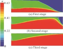
Fig. 2 (Color Online) Three stages of sand bank formation in numerical simulations
2. Distribution characteristics of proppant in SCCO2 in fractures
Figure 3 shows the contour of the proppant volume fraction in the vertical profile of the fracture.Figure 4 shows the proppant volume fraction in the fracture height direction of line a in Fig. 3, Fig. 5 shows the proppant velocity ()vin the fracture height direction of line b in Fig. 3. From Figs. 4, 5, we can summarize the cases as in the following Table 1

Fig. 3 (Color Online) The contour of proppant volume fraction in vertical profile of fracture. Boundary conditions: inlet mass flow rate: 2 kg/s, outlet pressure: 40 MPa, medium properties: proppant density: 2 540 kg/m3, proppant diameter: 40 mesh size, solid volume fraction: 30%, SCCO2 viscosity: 0.06 mPa·s

Fig. 4 The proppant volume fraction in the fracture height direction
From the vertical profile of the fracture as seen in Fig. 3, it is clear that we have four regions based on the concentration. The first region is the low sand area at the top of the fracture. In this region, the proppant volume fraction is less than 0.05, and the proppant velocity is over 0.15 m/s. The second region is a suspension area next to the low sand area. In this region, the proppant volume fraction ranges between 0.05 and 0.3. With the proppant concentration gradient, the proppant velocity is greater than 0.15 m/s.The third region is the tumble area below the suspension area with the proppant volume fraction between 0.3 and 0.6, and the proppant velocity is between 0.10 m/s and 0.65 m/s. The fourth and final region is the sand area at the bottom of the fracture with the proppant volume fraction more than 0.6, and its proppant velocity is less than 0.05 m/s.
3. Sand bank distribution comparison between SCCO2 and slick-water
Figure 6 shows the contours of the sand bank distribution, where the cases of the SC-CO2and theslick-water are compared. During the initial stage of proppant injecting (t= 5s), the forming speed of the sand bank in the SC-CO2is greater than that of the slick-water. Because the density of the SC-CO2is less than that of the slick-water under the condition of the same mass inflow rate and solid volume fraction, and the proppant volume injected in the SC-CO2is more than that in the slick-water per unit time. Meanwhile the fluidization ability of the slick-water is better than that of the SC-CO2. Thus, with lower sedimentation velocities of the proppant in the slick-water, we will have longer proppant transport-this means settling closer to the outlet. The proppant in the SC-CO2first reaches the largest filling state in the fracture (t=40s) while the proppant in the slick-water reaches the largest filling state later in the fracture (t= 100 s).
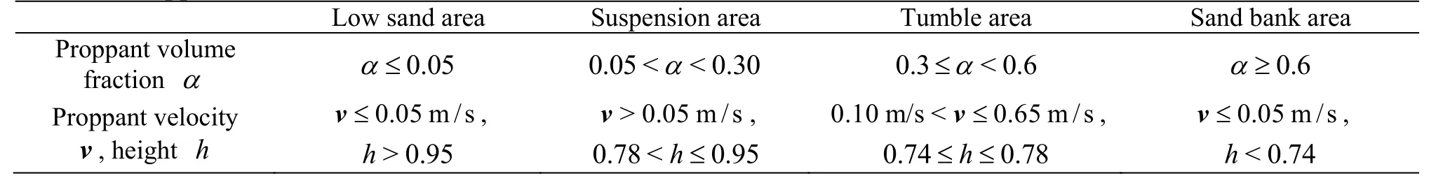
Table 1 Proppant distribution characteristics

Fig. 6 (Color Online) Comparisons of the contours of sand bank distribution between SC-CO2 and slick-water
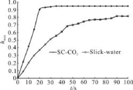
Fig. 7 The comparison of the maximum height of the sand bank between SC-CO2 and slick-water at different times
Figure 7 compares the maximum heightmax( )hof the sand bank between the cases of the SC-CO2and the slick-water in different time intervals ()t. The maximum height of the sand bank in the SC-CO2is larger than that in the slick-water at all time points,and its height difference first increases and then is maintained unchanged. Before the time of 20 s, the height of the sand bank in the SC-CO2increases rapidly. From =20stto =35st, the height of the sand bank increases slowly and then after =35st,the height stabilizes to a constant value. For the slickwater, the height of the sand bank increases slowly until the time of 90 s. After that it keeps unchanged.The equilibrium time in the SC-CO2is shorter than that of the slick-water but the equilibrium height in the SC-CO2is greater than that in the slick-water. Therefore under the same condition, the slick-water has a stronger sand-carrying ability than the SC-CO2.Further study is needed to ensure that the proppant in the SC-CO2and in the slick-water has a similar filling effect.
4. Sensitivity analysis
4.1 Proppant density
Figure 8 shows the dimensionless equilibrium heights and equilibrium time for different proppant densities. The velocity of the proppant sedimentation,and the dimensionless equilibrium height increase with the increase of the proppant density. The equilibrium time decreases with the increase of the proppant density. When the proppant density is small, such as 1 040 kg/m3, the proppant could not easily settle to form a sand bank because it has a strong proppant fluidization ability. Therefore, the height of the sand bank is less than 60% of the fracture height, and the equilibrium time is close to 60 s. Conversely, increasing the proppant density can help the proppant to settle and form a sand bank in a shorter time.Therefore reducing the proppant density can reduce the equilibrium height and thus the risk of sand plugging-this ensures a uniform proppant settlement in the fracture, as discussed before, with a similar filling effect as that of the slick water.

Fig. 8 The dimensionless equilibrium heights and equilibrium time for different proppant densities
4.2 Solid volume fraction
Figure 9 shows the dimensionless equilibrium heights and equilibrium time for different solid volume fractions. As shown in Fig. 9, the dimensionless equilibrium height increases slightly with the increase of the solid volume fraction, while the equilibrium time decreases substantially. This is because the convective proppant transport effects increase with the increase of the solid volume fraction and the proppant sedimentation becomes faster. The sand-carrying fluids with a high solid volume fraction make it easy to form a sand plug in the fracture at early stages of the SC-CO2fracturing. Therefore, to achieve a longer fracture requires a lower solid volume fraction, on the other hand, to achieve a higher fracture requires a higher solid volume fraction. What is more, the solid volume fraction does not have much influence on the equilibrium height. That means that the solid volume fraction can not be used to control the height of the vertical fracture.

Fig. 9 The dimensionless equilibrium heights and equilibrium time for different solid volume fractions
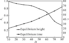
Fig. 10 The dimensionless equilibrium heights and equilibriumtime for different proppant diameters
4.3 Proppant diameter
Figure 10 shows the dimensionless equilibrium heights and equilibrium time for different proppant diameters ()D. The dimensionless equilibrium height increases with the increase of the proppant diameter,while the equilibrium time decreases. With the diameter size of 10 mesh, the proppants show the strongest wall effect[17], the fastest sedimentation, the largest porosity of the sand bank, the largest dimensionless equilibrium height, and the shortest equilibrium time. Therefore, when the fracture length is long enough, a sand plug easily occurs because for the proppants with large diameters, we will have a large dimensionless height. The proppant cannot be transported to the remote section of the fracture. With a sand diameter as commonly adopted (20/40 mesh) in the slick water fracturing, long fractures could not be achieved in the SC-CO2fluid. Consequently, a small proppant diameter is an advisable choice to achieve a longer fracture, but with a lower height.
4.4 Mass inflow rate
Figure 11 shows the dimensionless equilibrium heights and equilibrium time for different mass inflow rates ()Q. As shown in Fig. 11, both the equilibrium height and the equilibrium time decrease with the increase of the mass flow rate. Considering the cases of the mass inflow rates of 1.0 kg/s and 1.5 kg/s, the equilibrium time at the mass inflow rate of 1.5 kg/s is less than that at the mass inflow rate of 1.0 kg/s because the higher the mass inflow rate, the higher the injected proppant volume per unit time-this decreases the time needed to form a sand bank. The dimensionless equilibrium height at the mass inflow rate of 1.5 kg/s is less than that at the mass inflow rate of 1.0 kg/s. A higher mass inflow rateleads to a larger injected proppant velocity. In turn, we will have a larger suspension area and a larger tumble area and a smaller sand bank area, which leads to a longer fracture at a shorter time.

Fig. 11 The dimensionless equilibrium heights and equilibrium time for different mass inflow rates
5. Conclusions
(1) The proppant concentration varies in vertical fractures of the SC-CO2fracturing. Based on proppant volume fraction, velocity and dimensionless height,these fractures can be divided into four regions-the low land area, the suspension area, the tumble area and the sand bank area. Of these four areas, the sand bank area and the suspension area are two key areas to determine the fracture shape.
(2) The slick-water enjoys a better sand-carrying ability than the SC-CO2, thus the proppant could form a higher sand bank at a shorter time in the SC-CO2fluid compared with the slick-water, which means that the SC-CO2can lead to higher but shorter fracture compared with the slick water under the same condition.
(3) In the SC-CO2fracturing, there are positive correlations between the proppant density, the proppant diameter, the solid volume fraction and the dimensionless equilibrium height, equilibrium time, as well as between the mass inflow rate and the equilibrium time and a negative correlation between the mass inflow rate and the dimensionless equilibrium height.
(4) The results indicate that reducing the density of the proppant, the grain size of the proppant and the solid volume fraction or increasing the injection rate during the SC-CO2fracturing, we will have longer vertical fractures, but with lower height, thus the proppant will have similar filling effects as in fractures of the slick water fracturing. This study verifies the feasibility of the proppant transport by the SC-CO2fracturing in fractures. It provides a basis for the SC-CO2fracturing design.
Acknowledgement
This work was supported by the Science Foundation of China University of Petroleum, Beijing(Grant No. 2462013BJRC002).
[1] Hou L., Sun B., Li Y. et al. Impact of unconventional oil and gas exploitation on fracturing equipment and materials development [J].Natural Gas Industry, 2013, 33(12):105-110(in Chinese).
[2] Dong D., Zou C., Yang H. et al. Progress and prospects of shale gas exploration and development in China [J].Acta Petrolei Sinica, 2012, 33(1): 107-114(in Chinese).
[3] Sakmar S. L. Shale gas development in North America:An overview of the regulatory and environmental challenges facing the industry [C].North American Unconventional Gas Conference and Exhibition. The Woodlands,USA, 2011.
[4] Touzel P. Managing environmental and social risks in China [C].International Conference on Health, Safety and Environment in Oil and Gas Exploration and Production.Perth, Australia, 2012.
[5] Anderson R. L., Ratcliffe I., Greenwell H. C. et al. Clay swelling-A challenge in the oilfield [J].Earth-Science Reviews, 2010, 98(3-4): 201-216.
[6] Shen Z., Wang H., Li G. Feasibility analysis of coiled tubing drilling with supercritical carbon dioxide [J].Petroleum Exploration and Development, 2010, 37(6):743-747.
[7] Wang H., Shen Z., Li G. Feasibility analysis on shale gas exploitation with supercritical CO2[J].Petroleum Drilling Techniques, 2011, 39(3): 30-35(in Chinese).
[8] He Z. G., Li G. S., Wang H. Z. et al. Numerical simulation of the abrasive supercritical carbon dioxide jet: The flow field and influence factors analysis [J].Journal of Hydrodynamics, 2016, 28(2): 238-246.
[9] McClure M., Babazadeh M., Shiozawa S. et al. Fully coupled hydromechanical simulation of hydraulic fracturing in 3D discrete-fracture networks [J].SPE Journal,2017, 21(4): 1302-1320.
[10] Gomaa A., Hudson H., Nelson S. et al. Computational fluid dynamics applied to investigate development of highly conductive channels within the fracture geometry[J].SPE Production and Operations, 2017, 32(4):392-403.
[11] Liu Y. Settling and hydrodynamic retardation of proppants in hydraulic fractures [D]. Doctoral Thesis, Austin, USA:The University of Texas, 2006.
[12] Li L., Wang Z., Qiu Z. et al. An experimental study on carrying cuttings features for supercritical carbon dioxide drilling fluid [J].Acta Petrolei Sinica, 2011, 32(2):355-359(in Chinese).
[13] Shen Z. H., Wang H. Z., Li G. S. Numerical sumilation of the cutting-carrying ability of supercritical carbon dioxide drilling at horizontal section [J].Petroleum Drilling Techniques, 2011, 38(2): 233-236(in Chinese).
[14] ANSYS Inc. ANSYS FLUENT 12.0 theory guide [M].ANSYS Inc., 2009, 558-569.
[15] Peng D. Y., Robinson D. B. A new two-constant equation of state [J].Industrial and Engineering Chemistry Fundamentals, 1976, 15(1): 59-64.
[16] Span R., Wagner W. A new equation of state for carbon dioxide covering the fluid region from the triple-point temperature to 1100 K at pressures up to 800 MPa [J].Journal of Physical and Chemical Reference Data, 1996, 25(6): 1509-1596.
[17]Li X., Li G., Wang H. et al. A coupled model for predicting flowing temperature and pressure distribution in drilling ultra-short radius radial wells [C].IADC/SPE Asia Pacific Drilling Technology Conference, Singapore, 2016.[18] Li X., Li G., Wang H. et al. A unified model for wellbore flow and heat transfer in pure CO2injection for geological sequestration, EOR and fracturing operations [J].International Journal of Greenhouse Gas Control, 2017, 57:102-115.
[19] Aungier R. H. A fast, accurate real gas equation of state for fluid dynamic analysis applications [J].Journal of Fluids Engineering, 1995, 117(2): 277-281.
[20] ANSYS Inc. ANSYS FLUENT 12.0 user’s guide [M].ANSYS Inc., 2009, 593-604.
[21] Liu Y. Sharma M. M. Effect of fracture width and fluid rheology on proppant settling and retardation: An experimental study [C].SPE Annual Technical Conference and Exhibition. Dallas, USA, 2005.
[22] Wang F. J. Computational fluid dynamics analysis-theory and application of CFD software [M]. Beijing: Tsinghua University Press, 2004, 196-200(in Chinese).
杂志排行

水动力学研究与进展 B辑的其它文章
- Numerical simulation of wave-current interaction using the SPH method *
- The coupling between hydrodynamic and purification efficiencies of ecological porous spur-dike in field drainage ditch *
- Simulation of violent free surface flow by AMR method *
- Experimental research on kinematics of breaking waves *
- Fundamental problems in hydrodynamics of ellipsoidal forms *
- Case study on wave-current interaction and its effects on ship navigation *