Effect of blade shape on hydraulic performance and vortex structure of vortex pumps *
2018-07-06YapingJu琚亚平SiLiu刘思ChuhuaZhang张楚华
Ya-ping Ju (琚亚平), Si Liu (刘思), Chu-hua Zhang (张楚华)
1. School of Energy and Power Engineering, Xi’an Jiaotong University, Xi’an 710049, China
2. Shanghai Turbine Works, Shanghai Electric Power Generation Equipment Co. Ltd., Shanghai 200240, China
Introduction
The vortex pumps, also known as the regenerative or peripheral pumps, are capable of developing a high head at a low flow rate within a single stage. As a kind of blade pumps, the vortex pump primarily consists of a casing, an impeller, an inlet pipe, an outlet pipe and a stripper. As shown in Fig. 1(a), the casing forms an annular side channel and the impeller has a number of blades at the periphery of its rotating disc. The stripper is inserted downstream the outlet pipe to prevent the fluid leakage from the outlet pipe to the internal passage. As the impeller rotates, the fluid enters the pump through an inlet pipe, passes through the channel in a helical way, and then discharges out of the pump through an outlet pipe (Fig.1(b)). The helical flow pattern involves complicated vortex structures such as longitudinal, radial and axial vortices, allowing the fluid particles to circulate in a repeated or regenerative way between the side channel and the rotating impeller (Fig. 1(c)). These repeated vortex structures enable a single-stage vortex pump to develop a head 2-4 times higher in comparison with that developed by a single-stage centrifugal pump at the same tip speed[1-2]. In addition to this hydrodynamic merit, the vortex pump also has a compact size and is easy to manufacture with a low cost. Therefore,the vortex pump has increasingly become an important alternative or supplement to the centrifugal pump[3], the positive displacement pump and even the diffusion pump[4], and found successful applications in industrial fields such as the chemical engineering, the refrigeration, the fuel cell, the aerospace, the vacuum and the medical devices.
Compared with the other types of blade pumps such as the axial-flow and centrifugal pumps, the vortex pumps are. however, not well studied. Historically, diverse theories were put forward to interpret the working mechanisms of the vortex pump, among which the momentum exchange theories were found to be more precise, as presented by Song et al.[5], Yoo et al.[6]and Meakhail et al.[7]. According to the momentum exchange theories, some 1-D analytical models and flow loss models were developed by Quail et al.[8,9]and Liu[10]to predict the hydraulic performance of the vortex pumps, and were also extended by Badami and Mura[11]and Song et al.[12]to predict the aerodynamic performance of the vortex blowers and compressors. However, since these simplified models rely heavily on empirical correlations, or experimental and CFD data, they fail to reveal the 3-D internal flow field and are only limited to the stage of the preliminary design of the vortex pumps.
To develop more advanced vortex pumps via the modern design optimization tools[13-16], an important step is to understand how the blade geometry affects the hydraulic performance as well as the internal flow of the vortex pump. The computational fluid dynamics(CFD) method based on the 3-D fully viscous flow model offers a more precise way to not only predict the performance, but also reveal the detailed flow structures in the vortex pumps[17-18]. Furthermore, the CFD results can be used to validate or revise the 1-D simplified models, and to supplement or interpret the experimental measurements[19]. However, to our best knowledge, most CFD studies of the vortex pumps were limited to the cases of 2-D radial straight blades,and the studies of the vortex pumps with twisted blades or 3-D blades[7,20]were few, which are,however, important issues for further improvements of the hydraulic performance of the vortex pumps, and therefore for the technological advancements and the wide applications of the vortex pumps.
In the present study, two types of new blades,namely 2-D and 3-D corner blades, are introduced to the design of the vortex pump. Primary efforts are devoted to numerically investigating the effect of different blade shapes on the hydraulic performance and the vortex structures of the vortex pumps. This work is expected to provide a theoretical basis for the future design optimization of advanced vortex pumps.
1. Methodology
1.1 Concept of corner blades
The baseline vortex pump under consideration is provided by Daikin LTD, with a rectangular crosssection for its annular side channel and traditional 2-D radial straight blades. Important dimensions and operating conditions of this baseline pump are listed in Table 1.
To improve the hydraulic performance of this vortex pump, two types of new blades, namely 2-D and 3-D corner blades, are proposed and investigated in this study. Here the term corner means that both sides of the impeller blade form a corner shape rather than a straight shape at the symmetric line of the impeller, as illustrated in Fig. 2. In Fig. 2(a), two parameters, β and γ, are introduced to define the blade setting angles at the hub and the tip, respectively.Accordingly, the traditional 2-D radial straight blade is characterized by β = γ = 90°, the 2-D corner blade by β = γ ≠90°, and the 3-D corner blade by β≠γ,i.e., a kind of twisted blades. Note that here the 3D corner blade is as in a ruled surface of straight lines joining corresponding points on the hub and tip contours. For either the 2-D or 3-D corner blade, it is defined to beforward if γ>90° and backward if γ < 90°.

Fig. 1 (Color online) Schematic diagrams of the vortex pump
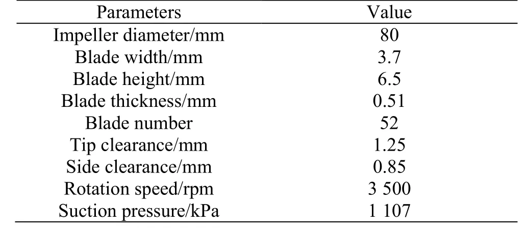
Table 1 Main parameters of the baseline vortex pump
In this study, the hydraulic performances of 13 vortex pumps with different corner blades (β=γ=60°, 80°, 100°, 110°, 120°, 130° and 140° for 2-D corner blades, and β=90°,γ= 60°, 80°, 100°, 110°,120° and 130° for 3-D corner blades) are numerically investigated and compared with that of the baseline pump with radial straight blades (β = γ = 90°). In all these cases, the hub and casing profiles, the clearances,the blade number and the blade thickness are kept unchanged.
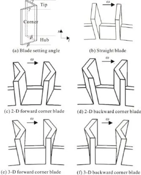
Fig. 2 Geometry descriptions of the blade
1.2 CFD model
The hydraulic performance of the vortex pump is obtained by the numerical solution of the 3-D steady incompressible Reynolds-averaged Navier-Stokes equations through a finite-volume method solver, the Fluent 6.3. The S-A turbulence model is adopted to close the turbulence terms. The convection terms of the governing equations are discretized by the secondorder upwind scheme and the diffusion terms by the second-order central scheme. The pressure-based SIMPLE algorithm is employed to treat the flow velocity-pressure coupling.
The impeller region is set to be rotational while the other flow domains are set to be stationary. The rotor-stator interfaces are modeled by the multiple reference frame (MRF) approach or the frozen rotor technique. This rotor-stator treatment technique was recently applied to study the vortex pumps[9]and the
vortex blowers[11]with acceptable accuracy for the performance and the flow patterns. At the inlet, the total pressure is fixed to be 1 107 kPa and the flow direction is specified to be normal to the boundary. At the outlet, the static pressure is given and adjusted within the range from 1 207 kPa to 2 507 kPa for different flow rates. Nonslip conditions are applied to the solid walls. The efficiency of the vortex pump in this study is defined as follows
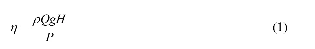
whereQis the volumetric flow rate,His the pump head andPis the pump input power.
The multi-block structured grids are generated in the computational region (Fig. 3). To better capture the boundary layer, the area-averaged+yof the first inner nodes close to the solid surface of the passage is generally kept below 5.0. The grid independence is examined for the baseline pump via successively increasing the grid number until the pump head and efficiency are essentially no longer changed. As shown in Table 2, three sets of grids are evaluated and the grid independence is achieved when the grid number is 1 129 785. Hereafter, the grid numbers of all the vortex pumps to be investigated in this study are kept around 1 130 000.
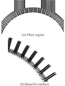
Fig. 3 Computational grids
Figure 4 shows the comparison of the pump efficiency η between the CFD results and the Daikin LDT measurements. As can be seen, the variation trend of the predicted efficiency curve is well consistent with the measurement data. The predicted value is slightly larger than the measurement data, which is reasonable and can be explained by the absence of the leakage flow, the disk resistances and the mechanical losses in the CFD simulation. Overally,the above CFD method is considered to be reliable in predicting the hydrodynamic performance of the vortex pump.
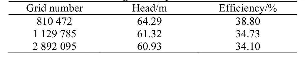
Table 2 Examination of grid independence
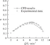
Fig. 4 Comparison of the pump efficiency between CFD results and experimental data
2. Results and discussions
2.1 2-D corner blades
2.1.1 Hydraulic performance
Figure 5 shows the calculated hydraulic performance curves of the vortex pumps with different 2-D blade shapes. In particular, the headHand the efficiency η of each vortex pump at the design point are listed in Table 3. In comparison with the radial straight blade, the 2-D forward corner blades are found to enjoy a better hydraulic performance in terms of the pump efficiency and head, while the 2-D backward ones show a worse hydraulic performance.In addition, the pump head is found to increase with the increase of the blade angle. At the blade angle of 130° (β = γ = 130°), the efficiency of the 2-D-blade vortex pump reaches the highest, i.e., 36.72%.
2.1.2 Vortex structure
For an insight into the performance improvement or deterioration of the above vortex pumps, the flows in three typical vortex pumps with the 2-D forward 130° blade, the straight blade and the 2-D backward 60° blade are analyzed, respectively. Hereafter, all flow fields investigated are within the impeller blade passage opposite to the pump stripper, which is considered in the developed flow region of the vortex pump. The flow fields in different planes within that passage, as illustrated in Fig. 6, are primarily examined in this study. As can be seen, Plane B-B is equivalent with the meridional plane while Planes A-A and C-C are perpendicular to the axial and radial directions, respectively.
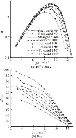
Fig. 5 Hydraulic performance curves of 2-D-blade vortex pumps
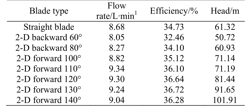
Table 3 Designpointperformanceof2-D-bladevortex pumps
Figure 7 shows the flow velocity vectors in the meridional plane (Plane B-B in Fig. 6), from which the longitudinal vortices in the vortex pumps can be clearly observed. In Fig. 7(a), the 2-D forward 130°blade is observed to have a pair of well-organized and strong longitudinal vortices with their centers approximately on the border line between the blade and the side channel. In that case, most of the fluids discharge from the blade tip rather than from the blade side.According to the momentum exchange theory presented by Song et al.[5], this allows a substantial centrifugal force to be imparted to the fluids and creates a large discharge tangential momentum to be transferred for the high head. In Fig. 7(c), the 2-D backward 60° blade is observed to have double pairs of longitudinal vortices. The pair of the primary vortices (downside) has a much weaker vortex intensity with their centers obviously inside the impeller blade passage. Consequently, most of the fluids leave the blade passage from the blade side rather than from the blade tip. Worse still, the pair of the secondary vortices (upside) near the blade tip induces the fluids to enter the impeller through the blade tip and to flow centripetally just as within a radial turbine. Such a turbine-like flow pattern is supposed to have a negative effect on the energy transfer from the impeller to the fluids. This explains why the vortex pump with the backward blade has a much lower head.As for the radial straight blade in Fig. 7(b), the longitudinal vortex flow is similar to, but obviously weaker than that in the forward corner blade.

Fig. 6 A schematic diagram of different planes in the pump passage
Figure 8 shows the relative flow velocity vectors in Plane C-C, which is close to the hub side where the flow incidences in the entry region of the blade passage can be observed. Due to the different blade angles (β) at the hub, the flow incidences are found to be different for those of the vortex pumps with different blade types. As can be seen, the 2-D forward 130° blade enables a good match between the blade shape and the relative flow, leading to relatively small incidence losses and hence a high efficiency of the vortex pump. In Fig. 8(b), the match between the blade and the relative flow is observed to become worse. For the 2-D backward 60° blade in Fig. 8(c),this match is further deteriorated with an even poorer flow guidance at the hub, with the largest incidence losses, which is adverse to the pump efficiency.
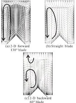
Fig. 7 Longitudinal vortices in 2-D-blade vortex pumps
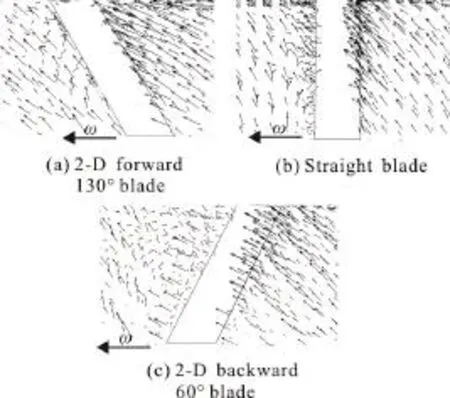
Fig. 8 Hub-side relative flow velocities in 2-D-blade vortex pumps
2.2 3-D corner blades
2.2.1 Hydraulic performance
For the 3-D-blade vortex pumps in this study, as previously mentioned, the blade angle β is fixed to be 90° at the hub while the angle γ varies from 60°to 130° at the tip. The calculated hydraulic performance curves of the vortex pumps with different 3-D corner blades are shown in Fig. 9. Table 4 lists the head and the efficiency of each vortex pump at the design point. As can be seen, the 3-D-blade vortex pumps have similar performance variation trends as the 2-D-blade vortex pumps. The 3-D forward corner blades are found to outperform the radial straight blade in terms of both the efficiency and the head,while the 3-D backward blades show poorer performance. In addition, compared with the 2-D-blade vortex pumps, the 3-D-blade vortex pumps generally show a higher pump efficiency and a lower head,except for the case of the 3-D backward 60° blade,which achieves a higher head than the 2-D backward 60° blade. The highest efficiency (38.49%) of the 3D-blade vortex pump at the design point is achieved at =120γ°.
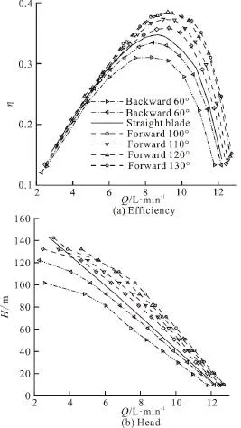
Fig. 9 Hydraulic performance curvesof 3-D-bladevortex pumps
2.2.2 Vortex structure
The flow fields in the three typical pumps with the 3-D forward 120° blade, the straight blade and the 3-D backward 60° blade are examined and analyzed as follows.
Figure 10 shows the flow velocity vectors in the meridional plane (Plane B-B). Similar to the 2-D blades in Fig. 7, the 3-D forward 120° blade performs the best while the 3-D backward 60° blade performs the worst owing to the structure of the longitudinal vortices. Compared with the 2-D corner blade, the 3-D forward blade is observed to have weaker longitudinal vortices and the fluids discharge from both the blade tip and the blade side (Fig. 10(a)). According to the momentum exchange theory[5], the 3-D forward corner blade can develop a smaller discharge tangential momentum and thus a smaller pump head than the corresponding 2-D forward corner blade. For the 3-D backward 60° blade in Fig. 10(c), although the negative secondary vortices (upside) at the blade tip are stronger than those of the 2-D backward 60° blade shown in Fig. 7(c), due to stronger primary vortices(downside) with their centers moving closer to the blade side, more fluids are allowed to be discharged for the momentum exchange. This explains why the 3-D backward 60° blade yields a higher pump head than the 2-D backward 60° blade.
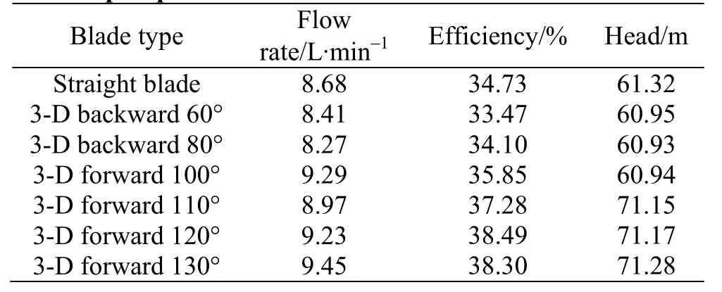
Table 4 Designpointperformanceof3-D-blade vortex pumps
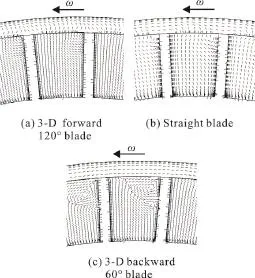
Fig. 11 Axial vortices in 3-D-blade vortex pumps

Fig. 12 Radial vortices in 3-D-blade vortex pumps
Since the investigated 3-D corner blades share the same blade angles at the hub (β= 90°), no significant differences are observed for the flow incidences near the entry region. Attention is thus directed towards the relative velocities in Plane C-C located at 50 percent point of the blade height, as shown in Fig.11. In this figure, the axial vortices within the impeller blade passage and the tip clearance vortices can be observed. Since the axial vortices are bounded by the blade surfaces and the impeller hub, they make small contributions to the momentum exchange of the fluids between the side channel and the impeller blade passage. Instead, the presence of the axial vortices disturbs the flow, with increased flow losses within the pump. Among the three blade types, the 3-D forward 120° blade is found to have the smallest axial vortex region, which helps to maintain a high pump efficiency. The tip clearance flow, driven from the blade pressure surface to the suction surface by the pressure difference, implies that the forward blade induces a smaller relative flow velocity and thus a larger absolute flow velocity in the tip clearance. This explains the relatively large design flow rate for the 3-D forward 120° blade as listed in Table 4. Figure 12 shows the relative velocities in Plane A-A of the three pumps, from which the structures of the radial vortices can be observed. Being bounded by the blade surfaces and the impeller disc, the radial vortices also contribute little to the momentum exchange but with flow losses, especially in the case of the 3-D backward 60°blade. Overally, the 3-D backward blade induces larger axial and radial vortices, with larger flow losses and thus a lower pump efficiency in comparison with the 3-D forward blade.
To sum up, the longitudinal vortices are mainly responsible for the head of the vortex pump while the pump efficiency is closely related to the flow incidences at the hub as well as the axial and radial vortices. A high-performance vortex pump should be characterized by well-organized longitudinal vortices,minimized flow incidences at the hub as well as minimized axial and radial vortices within the impeller blade passage.
3. Conclusions
A new design concept, namely the corner blade,is proposed for the vortex pump. Compared with the traditional radial straight blade, the 2-D and 3-D forward corner blades can be used to improve the hydraulic performance of the vortex pump in terms of efficiency and head while both 2-D and 3-D backward corner blades show a degraded hydraulic performance.
The pump head can be increased by strengthening the well-organized longitudinal vortices to drive more fluids to leave from the blade tip rather than from the blade side. The pump efficiency can be increased by reducing the incidence angle at the hub and by weakening the axial and radial vortices within the impeller blade passage.
The above findings are useful for improving the hydraulic performance of vortex pumps. Future work will take advantage of the modern design optimization methods to develop advanced vortex pumps.
[1] Tan P., Sha Y., Bai X. et al. A Performance test and internal flow field simulation of a vortex pump [J].Applied Sciences, 2017, 7(12):1273.
[2] Sha Y. Experiments on performance and internal flow of a vortex pump [J].Transactions of the Chinese Society of Agriculture Engineering, 2011, 27(4): 141-146.
[3] Mihalic T., Guzovic Z., Predin A. Performances and flow analysis in the centrifugal vortex pump [J].Journal of Fluid Engineering, 2013, 135(1): 011107.
[4] Shirinov A., Oberbeck S. High vacuum side channel pump working against atmosphere [J].Vacuum, 2011, 85(12):1174-1177.
[5] Song J. W., Engeda A., Chung M. K. A modified theory for the flow mechanism in regenerative flow pump [J].Proceedings of the Institution of Mechanical Engineers,Part A: Journal of Power and Energy, 2003, 217(3):311-321.
[6] Yoo I. S., Park M. R., Chung M. K. Improved momentum exchange theory for incompressible regenerative turbomachines [J].Proceedings of the Institution of Mechanical Engineers, Part A: Journal of Power and Energy, 2005,219(7): 567-581.
[7] Meakhail T., Park S. O. An improved theory for regenerative pump performance [J].Proceedings of the Institution of Mechanical Engineers, Part A: Journal of Power and Energy, 2005, 219(3): 213-222.
[8] Quail F. J., Stickland M. T., Scanlon T. J. Design optimisation of a regenerative pump using numerical and experimental techniques [J].International Journal of Numerical Methods for Heat and Fluid Flow, 2011, 21(1):95-111.
[9] Quail F. J., Scanlon T. J., Baumgartner A. Design study of a regenerative pump using one-dimensional and threedimensional numerical techniques [J].European Journal of Mechanics-B/Fluids,2012, 31: 181-187.
[10] Liu S. Investigation on performance prediction and design methods for vortex pumps [D]. Master Thesis, Xi’an,China: Xi’an Jiaotong University, 2013(in Chinese).
[11] Badami M., Mura M. Comparison between 3D and 1D simulations of a regenerative blower for fuel cell applications [J].Energy Conversion and Management,2012, 55: 93-100.
[12] Song J. W., Raheel M., Engeda A. A compressible flow theory for regenerative compressors with aerofoil blades[J].Proceedings of Institution of Mechanical Engineers,Part C: Journal of Mechanical Engineering Science, 2003,217(7): 1241-1257.
[13] Ju Y., Qin R., Kipouros T. et al. A high-dimensional design optimisation method for centrifugal impellers [J].Proceedings of Institution of Mechanical Engineers, Part A: Journal of Power and Energy, 2016, 230(3): 272-288.
[14] Ju Y. P., Zhang C. H. Multi-point and multi-objective optimization design method for industrial axial compressor cascades [J].Proceedings of Institution of Mechanical Engineers, Part C: Journal of Mechanical Engineering Science, 2011, 225(6): 1481-1493.
[15] Ju Y. P., Zhang C. H., Chi X. L. Optimization of centrifugal impellers for uniform discharge flow and wide operating range [J].AIAAJournal of Propulsion and Power, 2012, 28(5): 888-899.
[16] Jiang D. L., Lu J. X., Dai L. et al. A numerical simulation of and experimental research on optimum efficiency of vortex pumps [J].China Rural Water and Hydropower,2012, 4: 92-98.
[17] Kang S. H., Rye S. H. Reynolds number effects on the performance characteristics of a small regenerative pump[J].Journal of Fluid Engineering, 2009, 131(6): 061104.
[18] Karanth K. V., Manjunath M. S., Kumar S. et al. Numerical study of a self priming regenerative pump for improved performance using geometric modifications [J].International Journal of Current Engineering and Technology, 2015, 5(1): 104-109.
[19] Quail F. J., Stickland M., Scanlon T. Numerical and experimental design study of a regenerative pump [C].World Congress on Engineering 2009, London, UK, 2009.
[20] Angela G., Paul U. T., Sebastian W. et al. Design parameters of vortex pumps: a meta-analysis of experimental studies [J].Energies, 2017, 10(1): 58.
猜你喜欢
杂志排行

水动力学研究与进展 B辑的其它文章
- Numerical simulation of wave-current interaction using the SPH method *
- The coupling between hydrodynamic and purification efficiencies of ecological porous spur-dike in field drainage ditch *
- Simulation of violent free surface flow by AMR method *
- Experimental research on kinematics of breaking waves *
- Fundamental problems in hydrodynamics of ellipsoidal forms *
- Case study on wave-current interaction and its effects on ship navigation *