An integrated model for predicting the flame propagation in crimped ribbon flame arresters☆
2018-06-29ZhengWangBingSunQingshanHuangFuhuaJiang
Zheng Wang ,Bing Sun ,Qingshan Huang ,Fuhua Jiang *
1 Qingdao Institute of Bioenergy and Bioprocess Technology,Chinese Academy of Sciences,Qingdao 266101,China
2 State Key Laboratory of Safety and Control for Chemicals,SINOPEC Research Institute of Safety Engineering,Qingdao 266000,China
3 Key Laboratory of Green Process and Engineering,Institute of Process Engineering,Chinese Academy of Sciences,Beijing 100190,China
1.Introduction
Crimped ribbon flame arresters are usually installed in the pipelines of the flammable and combustible gas or on the top of the storage tank[1,2].They allow the gas to pass through and prevent the passage of the burning flame.Improper design of the flame arresters may give rise to flameproof failure,which can result in a fire disaster and even lead to a great loss of lives and properties.The design method of numerical simulation is promising;however,its reliability and accuracy are greatly influenced by the mathematical model.An accurate mathematical model should be set up to help designing the crimped ribbon flame arresters.
Many experimental studies[3-5]have been conducted on the flame arresters,but numerical studies are less.To the best of our knowledge,only Wanget al.[6]did a pioneering experimental and numerical study to investigate flame propagation and quenching in the microchannel of crimped ribbon flame arresters.There are few studies on the microchannel of flame arrester;however,many studies[7-9]have been done on the micro-combustor.Since both microchannels of flame arresters and micro-combustors are micro-size space involving flame propagation,some important conclusions obtained in the microcombustors can be learned and extended for studying the microchannel in flame arresters.The laminar model was usually assumed in the predictions of micro-combustor[10-12].Wanget al.[6]also used the laminar model to predict the flame characteristics in the microchannel of crimped ribbon flame arrester.The fuel enters the micro-combustor with tens of centimeters per second,but the fluid velocity at the entrance of the microchannel of flame arresters is more than tens of meters per second.That is to say,the fluid velocity at the inlet of the microchannel in the flame arresters is more than hundreds of times greater than that of the micro-combustor.Additionally,because the triangle microchannel yields the highest flame turbulence intensity[13],mixing between the components is enhanced.Moreover,violent chemical reaction flow is usually in a chaotic flow pattern[14,15].Thus,whether the laminar model is suitable to predict the flame propagation in the microchannel of the flame arresters or not,especially for the triangle mircochannel of crimped ribbon flame arresters,is worth discussing,and more studies on the flow regime of the flame propagation in the microchannel of the flame arresters need to be carried out.
Since there are violent combustion reactions in the crimped ribbon flame arresters,the chemical kinetics mechanism of flammable mixtures is very important to establish the accurate mathematical model.Propane has been widely used in applications such as gas turbines and water heating due to advantages of cost savings,widely available and convenient storage[16-19].Owing to its importance,oxidation of propane has therefore been intensively investigated by experiments since 1980s[20-24].Scholars have proposed a variety of kinetics mechanisms for the system of propane-air,and some numerical studies[25,26]containing the chemical kineticsmechanisms of propane-air mixtures have been conducted in recent years.For example,Wanget al.[6]utilized a single step mechanism for propane-air to study the relationship between the flameproof velocity and the arrester structure;Mansouriet al.[27]employed a simplified chemical kinetics mechanism of propane-air,which consists of 3 chemical reactions and 5 species,to investigate the effect of hydrogen addition and equivalence ratio on characteristics of premixed propane-air flame in a burner;Konakovet al.[28]used a one step global mechanism to investigate the flame shape and its long term stability;Luoet al.[29]adopted a simplified propane oxidation reaction kinetics to investigate the transition from deflagration to detonation in an explosive vessel with three barriers.Although great achievements have been made,few comparative studies of the sensitivity of the chemical kinetics mechanisms on the accuracy of numerical prediction have been taken yet.To the best of the authors' knowledge,only Gutkowski[30]compared the performance between the one step and two steps propane-air chemical kinetics mechanisms on the flame behaviour under quenching conditions for the flame propagating of propane-air mixtures in square cross-sections channels.Therefore,further studies of the sensitivity of chemical kinetics mechanisms on the prediction of flame quenching in the flame arresters should be undertaken.Since it is difficult to determine whether the flame is extinguished or not in the microchannel with the numerical method,scholar gave a very wide temperature range[6]as the judging criterion of quenching.Since it is not suitable for industrial applications,a scientific criterion for the flame quenching in numerical simulation should be established.
In the present work,an integrated mathematical model for the prediction of the reactive flow under high temperature in the microchannel of the crimped ribbon flame arresters isestablished,and the sensitivities of four chemical kinetics mechanisms of propane-air on the accuracy of flame propagation characteristics are investigated.An accurate chemical kinetics mechanism is identified and recommended for predicting the violent combustion reaction in the microchannel of the crimped ribbon flame arresters.The fluid flow regime of the flame propagation in the microchannel of the crimped ribbon flame arresters under the deflagration and detonation condition is determined,and a judging criterion of the flame quenching for the numerical method is proposed.The details of the flame propagation in the triangle microchannel including the distributions of temperature and species mass fraction are captured.The deep understanding of propane-air combustion and extinction characteristics in the microchannel is also obtained.It is indicated that the integrated mathematical model validated in this work can be used as a reliable tool for the modeling,designing and selecting of the industrial crimped ribbon flame arresters.
2.Physical Structure and Mathematical Model
2.1.Physical structure
A crimped ribbon flame arrester,as described in Fig.1(a),consists of an arrester housing,an arrester element and other associated fittings.When the flame passes through the arrester,it penetrates into the microchannels of the arrester element which consisted of many isosceles triangular microchannels.Meanwhile,the flame is split into small flamelets.Since the microchannel could efficiently absorb heat,the flame could be quenched successfully.Hence,the microchannelis the critical part to quench the flame.The microchannel,as presented in Fig.1(b),was investigated as the physical structure in this work.
Two microchannels(physical structures A and B)with different structure parameters were extracted from the literature[6]to verify the mathematical model in this work,and the basic parameters of the microchannel were illustrated in Table 1.

Table 1 The basic parameters of physical structures A and B
The arrester housing has an expansion ratio β [β =D/d,wheredis the diameter of the pipeline,andDis the diameter of the arrester element as shown in Fig.1(a)].The flame enters the pipeline with the velocityV.Since the mass is conserved,the flame velocity at the entrance of the microchannel,uin,can be calculated asV/β2.
2.2.Mathematical model
For the purpose of reducing the computational cost and get an efficient and reliable solution,steady mathematical models are taken here[31].

Fig.1.The sketch of the crimped ribbon flame arrester:(a)crimped ribbon flame arrester;(b)the microchannel.
2.2.1.Governing equations
The conservations of continuity,momentum,and energy are kept in control volume,and these mathematical models can be expressed with the following equations.
(1)Continuity equation

The gas density is calculated using the ideal gas law.
(2)Momentum equation

wherepis the static pressure,ρg is the gravitational body force;is the stress tensor,and it is given by

where μ is the laminar viscosity;μtis the turbulent viscosity;Iis the unit tensor.For laminar simulation,ρk=0 and μt=0.
A standardk-ε equations is used here to solve the turbulent flow[32].

where

In the above equations,μ is the molecular viscosity.Gkrepresents the generation of turbulent kinetic energy due to the mean velocity gradients.C1ε=1.44,C2ε=1.92,σk=1.0,σε=1.3 andCμ=0.09.
(3)Energy equation

wherekeffis the effective conductivity.keff=k+kt,wherektis turbulent thermal conductivity andkt=Pr=0.85.Eis the total energy,tand it is defined as

whereh issensible enthalpy andh=∑jYjhj.For individual species,

whereTref=298.15 K.
The gas viscosity,specific heat and thermal conductivity are calculated as a mass fraction-weighted average of all species.The specific heat of each species is calculated using a piecewise polynomial fit of temperature.
2.2.2.Modeling of chemical reaction
The mixing and transport of chemical species were modeled by solving species transport conservation equations which described the convection,diffusion,and reaction sources for each component species.The local mass fraction of each speciesYi,is predicted through the solution of a convection-diffusion equation for theith species.The conservation equation takes the following form:

whereRiis the net production rate of speciesiby chemical reaction.

In Eq.(10),Jiis the diffusion flux of speciesi,which arises due to gradients of concentration and temperature.The dilute approximation(also called Fick's law)is utilized to model mass diffusion due to concentration gradients,in which the diffusion flux can be written as,

whereDi,mis the mass diffusion coefficient or speciesiin the mixture.DT,iis the thermal diffusion coefficient,andSct=0.7.
Though detailed chemical kinetic calculations are computationally expensive,in order to predict precisely the effect of turbulent fluctuations on the chemical reaction,detailed Arrhenius chemical kinetics are incorporated in the turbulent flame by the Finite Rate/Eddy Dissipation Model(FR/EDM).
For the finite rate model,Ri,ris given by

The rate constant for reactionr,kf,ris computed using the Arrhenius expression:

The EDM is based on the hypothesis that the chemical reaction is fast in relation to the transport processes of the turbulent fluid flow.The reaction rate is assumed to be proportional to a mixing time defined by the turbulent kinetic energy(k)and the specific dissipation rate(ε).Based on the contribution of Magnussen and Hjertager[33],the net production rate of speciesidue to reactionr,Ri,r,is given by the smaller of the two expressions below
whereAis an empirical constant equal to 4.0;Bis an empirical constant equal to 0.5.
In Eqs.(15)and(16),the chemical reaction rate is governed by the large-eddy mixing time scale,k/ε,proposed in the eddy-breakup model of Spalding[34].The finite-rate/eddy-dissipation model,in which both the Arrhenius(Eq.(13)and eddy-dissipation(Eqs.(15)and(16))reaction rates are calculated,were employed.The netreaction rate is taken as the minimum of these two rates.For the laminar flow,the Arrhenius rate is taken.
Four different mechanisms(Jones and Lindstedt[23],Konakovet al.[28],Luoet al.[29],Mansouriet al.[27]),as presented in Tables 2-5,respectively,were applied to simulate propane-air combustion in the microchannel of crimped ribbon flame arresters.

Table 2 Oxidation kinetics of propane in Jones and Lindstedt[23]

Table 3 Oxidation kinetics of propane in Konakov et al.[28]

Table 4 Oxidation kinetics of propane in Luo et al.[29]
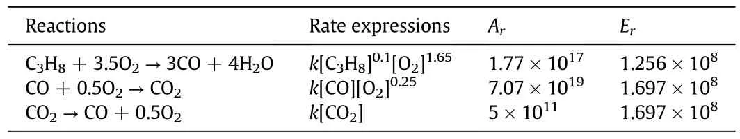
Table 5 Oxidation kinetics of propane in Mansouri et al.[27].
2.3.Boundary conditions
The boundary conditions are very important for getting correct simulation results of fluid flow[35,36].On the wall,no slip boundary condition is applied and the standard wall functions are adopted for all species at the solid wall[37-39],and a zero-gradient(zero- flux)boundary condition is set for all species.The temperature of the wall is isothermal(Twall=300 K).The boundary conditions at the inlet are set as a fixed inlet velocity,which is normal to the boundary of the inlet.The flame velocity at the entrance of the microchannel,uin,isV/β2.The inlet conditions for the turbulent kinetic energy and the dissipation rate are estimated by[31,40]

whereDHis the hydraulic diameter of the inlet.
The inlet temperature of the species was chosen to be 2300 K and the mass fractions of the reactants(C3H8and O2)were 0.064 and 0.232,respectively.
The outlet of the microchannel is treated as a fully developed boundary,and all the variables are subject to

Second order upwind scheme is used to discretize convective terms of all the governing equations,and the traditional SIMPLE(Semi-Implicit Method for Pressure Linked Equations)algorithm is adopted to deal with the pressure-velocity coupling.A 3D segregated solver with the under-relaxation method is employed to solve the conservation equations.The simulation convergence is judged by the residuals of the whole governing equations and the convergence criteria for the residuals are set to be 1.0×10⁻⁶for all the equations.
3.Results and Discussion
The experimental data in the contribution of Wanget al.[27]were used to verify the mathematical model.First,grid independence was conducted to ensure the results independent on the grid size.The flow pattern of the flame propagation in the microchannel was determined.Second,the mathematical model was verified and the most accurate chemical kinetics mechanism was screened.Third,temperature and species mass fraction profiles predicted by different chemical kinetics mechanisms for the physical structure A were compared.Finally,the temperature and species mass fraction profiles predicted by the most accurate chemical kinetics mechanism for the physical structure B were presented.
3.1.Grid independence
A fine grid size is essential for computational accuracy during the simulation,and correspondingly the computational cost is sharply increased.Therefore,a balance should be taken between the accuracy and the computational time.The grid independence study was performed for both physical structures A and B.Set the physical structure A as an example to illustrate this process.The predicted static temperature along the axial direction of the microchannel at the centerline is plotted in Fig.2.Preliminary computations with two folds finer grids were also conducted.As presented in Fig.2,there is no significant difference between the results obtained by these two sets of grids.Accordingly,the mesh intervals of 0.04 mm and 0.1 mm in the cross-section and the axial direction respectively are employed here to ensure higher accuracy as well as to reduce the computational time.

Fig.2.Study of grid independency.
3.2.Flow regime determination

Fig.3.μt/ μat the center surface:(a)the physical structure A;(b)the physical structure B.
The flow regime of the flame propagation in the microchannel is worth discussing.Because the inlet velocity is much smaller than that of the microchannel in the crimped ribbon flame arresters,some scholars utilized a laminar model to predict the flame characteristics in the micro-combustors.Since the inlet velocity of the flame entering the microchannel is up to tens of meters per second and there is violent combustion in the microchannel of the crimped ribbon flame arresters,the fluid flow regime may be turbulent.When the inlet velocity is equal to the flameproof velocity,the ratio of μt/ μ in the center surface of physical structures A and B are depicted in Fig.3.It is shown that the value ofμt/ μ is higher than 1 in the vast majority of zones.It is indicated that the flow pattern is turbulent in the microchannel of the crimped ribbon flame arresters.
In addition,when the inlet velocity is equal to the flameproof velocity,profiles of the predicted outlet temperature at the centerline in the axial direction of the physical structure A with the turbulent and laminar model are presented in Fig.4.It can be seen that the temperature predicted by the laminar model is much higher than that predicted by the turbulent one.The temperature profile predicted by the turbulent model is much closer to the experimental results.

Fig.4.Predicted outlet temperature profiles at the axial centerline of the physical structure A.
For the above two reasons,the flow regime of the flame propagation in the microchannel under the deflagration and detonation conditions is inferred to be turbulent.
3.3.Comparison with the experimental results
Three operating conditions(V<Vf,V=Vf,V>Vf, whereVandVfrepresent the flame velocity in the inlet of the pipeline and the flameproof velocity,respectively)were utilized to verify the mathematical model established here.The experimental data ofVandVfare extracted from the literature[6].
In this work,the auto-ignition temperature is adopted as the judging criterion,which is recommended as the quenching criterion by Zhouet al.[41]in the experiments.It is noteworthy that the auto-ignition temperature is the minimum temperature required to ignite the flammable mixture without a spark or flame being present.In other words,if the temperature of the hot products is higher than the auto-ignition temperature,the unburned gas behind the flame arrester can be ignited and thus a flame reemerges,which means the flame is failed to be quenched in the flame arresters.In contrast,if the outlet temperature is lower than the auto-ignition temperature,the flame could be quenched successfully.However,the temperature is uneven in the outlet,if one part or even one point of the outlet temperature is higher than the auto-ignition temperature,the flammable mixture can also be reignited,even though the temperature of all the other parts in the outlet are lower than the auto-ignition temperature.Therefore,the highest temperature value at the outlet surface is chosen here for comparing with the auto-ignition temperature of propane to verify the reliability of the mathematical model.

Fig.5.Predicted outlet temperatures for the physical structure A.

Fig.6.Predicted outlet temperatures for the physical structure B.
Figs.5 and 6 present the predicted outlet temperatures with different inlet velocity and chemical kinetics mechanisms for physical structures A and B,respectively.As illustrated in Fig.5,for the deflagration flame,whenV<Vf, the predicted outlet temperature is lower than the auto-ignition temperature,and vice versa.For the detonation flame,the predicted results of this integrated model show the same performance,as depicted in Fig.6.When the flame velocity is equal to the flameproof velocity[6],the predicted outlet temperature using the four kinetic models aforementioned is approximately equal to the auto-ignition temperature of propane-air with the deviation range of 0.11%-12.87%and 1.23%-8.92%for physical structures A and B,respectively.It is shown that the kinetics mechanisms are all good for industrial design if a turbulent model is applied.However,different kinetics mechanisms bring about different degrees of deviations.Therefore,with the aim of getting the reliable predicted results,it is essential to find the most accurate one to be integrated in the model of fluid flow.The computed values of deviations are depicted in Table 6.
相丰委员的问题很直接:“近几年市政府及有关部门在违建治理方面力度大、手段硬,效果明显,但个别区域违建现象仍然存在。创城成功之后,一些区域占道经营、店外经营现象有所反弹。对这些违法行为,条例都有明确规定,处罚措施也很具体。请问执法部门如何加大执法监管力度,加强违建治理,规范经营行为,保持市容市貌的整洁有序?”

Table 6 Deviations between the predicted outlet temperature and the auto-ignition temperature of propane-air
The deviation of prediction may be caused by the following reasons.First,the turbulent model is not accurate enough,and more studies are demanded.Second,there is a deviation between the inlet velocity adopted in the numerical simulation and the actual value in experiments.Since the inlet velocity of the microchannel is too difficult to measure due to the tiny dimension of the microchannel in the experiments,it is postulated as a uniform value ofV/β2in the numerical study.However,in the real system the velocity at the inlet of each microchannel has a slight difference from the postulated value because the velocity is uneven resulted from the influence of the physical structure of the arrester housing.As a consequence,these differences induce a deviation between the predicted outlet temperature and the autoignition temperature of propane-air.

Fig.7.Temperature distribution in the physical structure A with different kinetics:(a)Jones and Lindstedt[23];(b)Konakov et al.[28];(c)Luo et al.[29];(d)Mansouri et al.[27].
Although there are some deviations between the predicted values and the experimental values,the deviations are all within the range for the engineering applications,and it is indicated that the integrated model established here is reliable.The deviations presented in Table 6 are different for these four chemical kinetics mechanisms.It should be noted that though the deviation is small in the relative proportion,the absolute value is much higher.For example,the maximum deviation for the physical structure A predicted by the mechanism of Jones and Lindstedt[23]is-12.87%,and it means the predicted outlet temperature is 93.05 K lower than the auto-ignition temperature of propane-air.This indicates the chemical kinetics mechanism integrated in the mathematical model has great influence on the accurate prediction of the flame propagation in the microchannel.Since the outlet temperature predicted by the chemical kinetics mechanism of Mansouriet al.[27]among the four kinetics at the flameproof velocity has the relatively small deviation with the auto-ignition temperature of propaneair for both physical structures A and B,it is identified as the most accurate one to be integrated with the fluid flow model to predict the flame propagation in the microchannel.Consequently,it can be applied for the further industrial applications.
3.4.Results for the physical structure A
The integrated mathematical model could predict the temperature distribution and species mass fractions distribution accurately for both physical structures A and B,and the results indicate the integrated model is robust.Since the effect of chemical kinetics mechanisms on the distributions of temperature and the species mass fraction in two physical structures(A and B)is similar,only the results in the physical structure A are compared.In addition,to facilitate the comparison of the species mass fraction distribution predicted by different chemical kinetics mechanisms,only the common components(C3H8,H2O,CO2and H2O)in the four mechanisms are revealed.Some specific species(CO,H2)in the chemical kinetics mechanisms of Jones and Lindstedt[23],Luoet al.[29]and Mansouriet al.[27]are not presented.
3.4.1.Effect of chemical kinetics mechanism on temperature
In order to show vividly the simulation results,the center surface at the axial direction in the physical structure A is extracted.
Fig.7 shows the temperature distribution predicted by different chemical kinetics mechanisms in the center surface of the physical structure A when the inlet velocity is equal to the flameproof velocity.Fig.7(a)-(d)represents the predicted results by chemical kinetics mechanisms from Jones and Lindstedt[23],Konakovet al.[28],Luoet al.[29]and Mansouriet al.[27],respectively.It is shown that the temperature rises first in all simulations because the flammable gas releases a significant amount of heat through combustion.Then it drops greatly due to heat loss from the cold wall.However,different chemical kinetics mechanisms give different temperature distributions.Since there are 6 steps of reactions and 2 steps of them are reverse reactions that absorbed the heat,the temperature distribution predicted by the chemical kinetics mechanism from Luoet al.[29]is more uniform than the others.In contrast,there is only 1 step reverse reaction in the model from Mansouriet al.[27],and no reverse reaction in the other two chemical kinetics mechanisms and hence a relatively sharp change of temperature is observed.
3.4.2.Effect of chemical kinetics mechanism on species mass fraction distribution
The comparison of species mass fraction distributions predicted by different chemical kinetics mechanisms for the physical structure A at the flameproof velocity is presented in Figs.8-11,where(a)-(d)represent the chemical kinetics mechanism from Jones and Lindstedt[23],Konakovet al.[28],Luoet al.[29]and Mansouriet al.[27],respectively.

Fig.8.Mass fraction of C3H8 for the physical structure A:(a)Jones and Lindstedt[23];(b)Konakov et al.[28];(c)Luo et al.[29];(d)Mansouri et al.[27].

Fig.9.Mass fraction of O2 for the physical structure A:(a)Jones and Lindstedt[23];(b)Konakov et al.[28];(c)Luo et al.[29];(d)Mansouri et al.[27].
As revealed in Fig.8,the mass fraction of C3H8is the highest at the inlet of the microchannel,and then it decreases drastically due to consumption of propane as the chemical reaction goes on.Finally,mass fraction of C3H8tends to be stable because the stop of the reactions in the microchannel of the crimped ribbon flame arresters when the flame is quenched.This is consistent with the law of the propane combustion.
3.4.2.2.Reactant of O2.The mass fractions for reactant of O2predicted by different chemical kinetics mechanisms are presented in Fig.9.
As shown in Fig.9,the mass fraction of O2is the highest at the inlet of the microchannel,and then it decreases due to the reaction of propane oxidation.The mass fraction of O2is different along the axial direction due to the different consumption rates of O2.For the Konakovet al.[28],O2is consumed quickly due to the fact that C3H8reacts with O2to produce CO2and H2O.However,for the chemical kinetics mechanisms from Luoet al.[29]and Mansouriet al.[27],O2is consumed smoothly because C3H8is oxidized to CO at first,and then to CO2.The mass fraction of O2predicted by the chemical kinetics mechanism from Jones and Lindstedt[23]is bigger than the other three,as a result of the reason is that CO,which needs less O2,is the main product.
3.4.2.3.Product of CO2.The mass fractions for product of CO2predicted by different chemical kinetics mechanisms are revealed in Fig.10.
As presented in Fig.10,there is no product of CO2at the inlet of the microchannel.As the reaction goes on,the mass fraction of CO2increases with different rates.On one side,for the chemical kinetics mechanism of Mansouriet al.[27],there is little CO2in the first half position of the microchannel,and CO2is produced in the second half of the microchannel.The reason is that C3H8is oxidized to be CO at first,and then CO is oxidized to CO2finally.For Konakovet al.[28],the mass fraction of CO2tends to remain a high value at the distance not far from the entrance of the microchannel.On the other side,for the chemical kinetics mechanisms from Luoet al.[29]and Jones and Lindstedt[23],the mass fraction of CO2increases first and then declines since the CO2decomposes to produce CO and O2.In particular,the mass fraction of CO2predicted by the chemical kinetics mechanism from Jones and Lindstedt[23]is much smaller than the other three,because CO is the main product and CO2is the by-product.
3.4.2.4.Product of H2O.The mass fractions for product of H2O predicted by different chemical kinetics mechanisms are illustrated in Fig.11.
As presented in Fig.11,there is no H2O at the inlet of the microchannel.As the reaction goes on,the mass fraction of H2O increases noticeably.Finally,mass fraction of H2O tends to keep unchanged.
The fundamental data depicted in Figs.8-11 are valuable since they are too difficult to get in the experiments due to the tiny dimensions of the microchannel.As a result,the understanding of propane-air combustion in the microchannel is deepened in this work.

Fig.10.Mass fraction of CO2 for the physical structure A:(a)Jones and Lindstedt[23];(b)Konakov et al.[28];(c)Luo et al.[29];(d)Mansouri et al.[27].
3.4.2.5.Influence of chemical kinetics mechanisms on the final position of reaction.Distributions of species mass fraction in the centerline of physical structure A predicted by four chemical kinetics mechanisms are plotted in Fig.12.For Mansouriet al.[27]and Konakovet al.[28],CO2is the main product.On the contrast,CO is the main product predicted by the chemical kinetics mechanism from Jones and Lindstedt[23].Apparently,for the chemical kinetics mechanism from Luoet al.[29],the final mass fraction of CO and CO2is approximately equal.Additionally,species mass fractions of the other products are different.Besides,if a chemical reaction is in progress in the microchannel,the concentrations of the reactants will reduce and the product concentration will increase[30].When the mass fractions of species reduce to be a constant,the reaction is complete.From Fig.12,we can infer that different chemical kinetics mechanisms bring about different final position of reaction.The final positions of reaction are 4 mm,4 mm,8 mm and 10 mm for the mechanisms from Jones and Lindstedt[23],Konakovet al.[28],Luoet al.[29]and Mansouriet al.[27],respectively.
3.5.Results for the physical structure B
Because the chemical kinetics mechanism of Mansouriet al.[27]among the four chemical kinetics models is the most accurate one to predict the flame propagation in the microchannels,the temperature and species mass fraction profiles at the center surface of the physical structure B with the chemical kinetics mechanism of Mansouriet al.[27]are revealed in Fig.13.The temperature rises first since propane combustion releases heat,and then declines enormously by the wall cooling effect.The propane is oxidized to the intermediate product of CO in the first half length,and finally CO is oxidized to produce the final product of CO2in the second half.
It can be inferred that the prediction with the integrated mathematical model established in this work agrees well with the experimental results qualitatively and quantitatively and the verified mathematical model can be applied for further design of the crimped ribbon flame arresters.
4.Conclusions
In this work,a reliable and accurate mathematical model including steady fluid flow at elevated temperatures,violent combustion reaction and heat transfer was set up.The turbulent model was used to predict the flame propagation in the microchannels of the crimped ribbon flame arresters under the deflagration and detonation conditions.Four chemical kinetics mechanisms on the prediction accuracy of the flame characteristics in the microchannel were investigated.
The following conclusions can be obtained in this work.First,the pattern of fluid flow in the microchannel of the crimped ribbon flame arresters with flame propagation is con firmed to be turbulent under the deflagration and detonation conditions.Second,the auto-ignition temperature of flammable gas instead of a wide range of temperatures could be taken as the judging criterion to determine whether the flame is quenched or not.Third,chemical kinetics mechanisms have a significant impact on the accuracy of prediction,and the kinetics mechanism of Mansouriet al.[27]among the four ones is the most accurate.The temperature and species mass fraction distributions in microchannels,which are too difficult to measure by the experimental method due to the tiny dimension of microchannels,are revealed.In other words,the fundamental insights into chemical reactions and heat loss are well portrayed and the effect of the cold wall for quenching the deflagration and detonation flames in the microchannels is also determined.Fourth,the final position of reaction in the microchannel could be predicted with the integrated model,but different chemical kinetics mechanisms give different final positions of reaction in the microchannel.
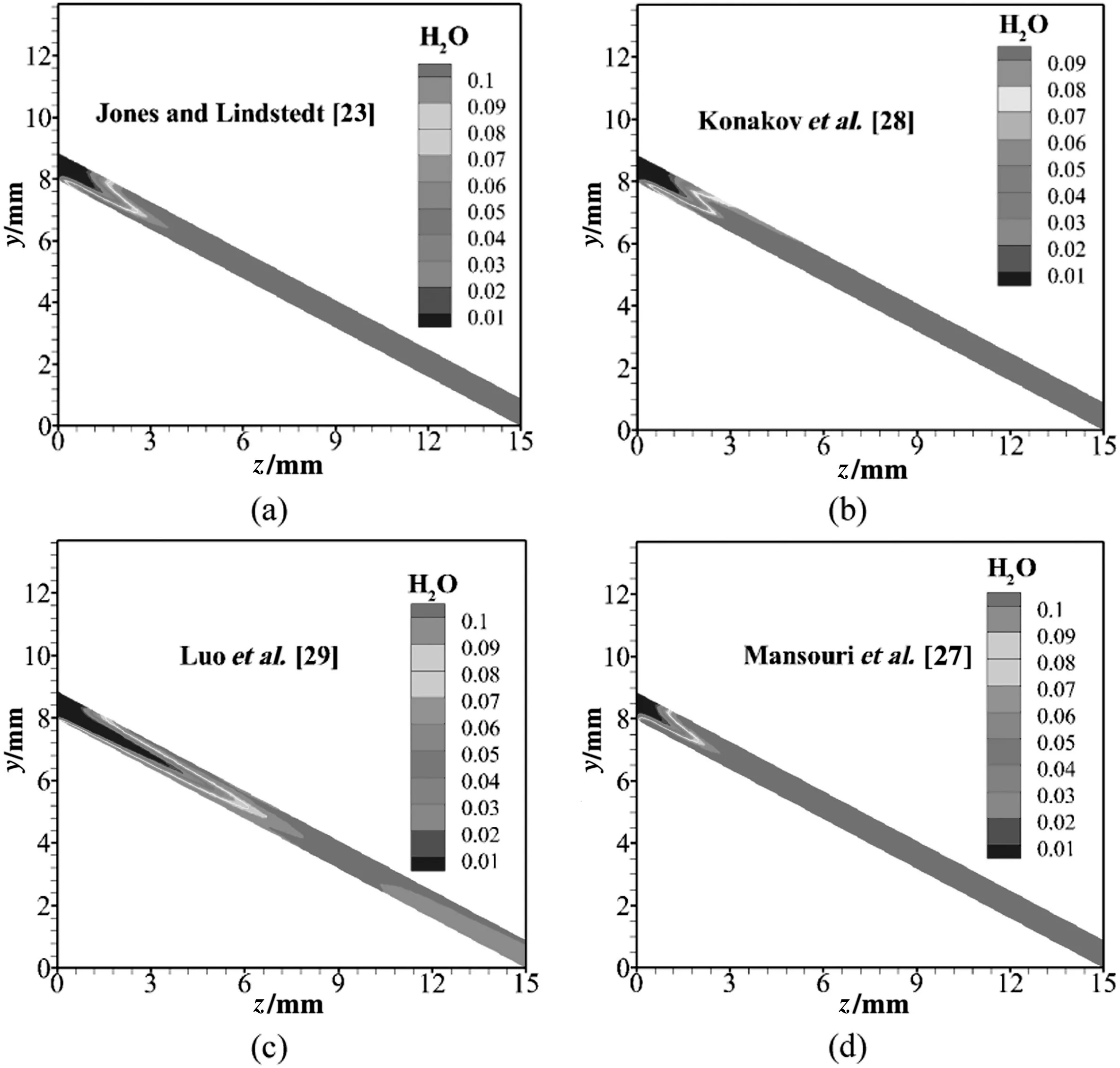
Fig.11.Mass fraction of H2O for the physical structure A:(a)Jones and Lindstedt[23];(b)Konakov et al.[28];(c)Luo et al.[29];(d)Mansouri et al.[27].

Fig.12.Species mass fraction profiles with different mechanisms for the physical structure A:(a)Jones and Lindstedt[23];(b)Konakov et al.[28];(c)Luo et al.[29];(d)Mansouri et al.[27].

Fig.13.Temperature and species mass fraction profiles predicted by the chemical kinetics mechanisms of Mansouri et al.[27]for the physical structure B:(a)temperature;(b)C3H8;(c)O2;(d)CO;(e)CO2;(f)H2O.
The obtained results demonstrate the capability of numerical approach in predicting the behavior of real accidental explosions.The integrated mathematical model verified in this work can be used as an effective tool for modeling,designing and choosing such type of crimped ribbon flame arresters with the propane-air medium in the future.
Nomenclature
Arpre-exponential factor,consistent units
athe bottom side length of the isosceles triangle,mm
Cj,rmolar concentration of speciesjin reactionr,kmol·m-3
Cp,jthe specific heat capacity of speciesj,J·(kg·K)-1
Dthe diameter of the arrester element,mm
dthe diameter of the pipeline,mm
Eractivation energy for the reaction,J·kmol-1
hthe height of the isosceles triangle,mm
hsensible enthalpy,h=∑jYjhj,J
hjthe sensible enthalpy of speciesj,J
Jjthe diffusion flux of speciesj,kg·(m-2·s)-1
kturbulent kinetic energy,m2·s3
kf,rforward rate constant for reactionr,kg·(m-3·s)-1
Mw,ithe molecular weight of speciesi
Mw,jthe molecular weight of speciesj
Mw,Rthe molecular weight of reactantR
NRNumber of reactions
pthe static pressure,Pa
Runiversal gas constant,J·(kmol-1·K)-1
Rithe net source of chemical speciesi,consistent units
Ri,rthe Arrhenius molarrate of creation/destruction of speciesiin reactionr,consistent units
Shthe heat of chemical reaction,J
uinvelocity at the entrance of the microchannel,m·s-1
uoverall velocity vector,m·s-1
Vvelocity at the pipeline,m·s-1
Vfflameproof velocity,m·s-1
Yjthe mass fraction of speciesj
YPthe mass fraction of any product speciesP
YRthe mass fraction of a particular reactantR
α the deflecting angle between the narrow channel and axial direction,(°)
β expansion ratio of flame arresters,dimensionless
γ the basic angle of the isosceles triangle,(°)
ε turbulent dissipation rate,m2·s3
η′j,rrate exponent for reactant speciesjin reactionr
η″j,rrate exponent for product speciesjin reactionr
ν′i,rstoichiometric coefficient for reactantiin reactionr
v″i,rstoichiometric coefficient for productiin reactionr
v″j,rstoichiometric coefficient for productjin reactionr
ν′R,rstoichiometric coefficient for reactantRin reactionr
ρ density,kg·m-3
the stress tensor,Pa
φ general variable
Subscripts
eff effective
f flameproof
H hydraulic
in inlet
ref. reference
tturbulent
Acknowledgments
Our gratitude goes to the Supercomputing Center of USTC(University of Science and Technology of China).
[1]D.Lietze,Crimped metal ribbon flame arrestors for the protection of gas measurement systems,J.Loss Prev.Process Ind.15(1)(2002)29-35.
[2]A.A.Pekalski,J.F.Zevenbergen,S.M.Lemkowitz,H.J.Pasman,A review of explosion prevention and protection systems suitable as ultimate layer of protection in chemical process installations,Process Saf.Environ.Prot.83(1)(2005)1-17.
[3]P.Bauer,Experimental investigation on flame and detonation quenching:applicability of static flame arresters,J.Loss Prev.Process Ind.18(2)(2005)63-68.
[4]C.Kersten,H.Förster,Investigation of deflagrations and detonations in pipes and flame arresters by high-speed framing,J.Loss Prev.Process Ind.17(1)(2004)43-50.
[5]Y.Okawa,C.Youn,T.Kagawa,A study of the characteristics of flow rate and extinction in a flame arrester with radial slit structure,J.Loss Prev.Process Ind.25(2)(2012)242-249.
[6]L.Wang,H.Ma,Z.Shen,The quenching of propane deflagrations by crimped ribbon flame arrestors,J.Loss Prev.Process Ind.43(2016)567-574.
[7]A.C.Benim,S.Iqbal,W.Meier,F.Joos,A.Wiedermann,Numerical investigation of turbulent swirling flames with validation in a gas turbine model combustor,Appl.Therm.Eng.110(2017)202-212.
[8]M.Choi,Y.Sung,M.Won,Y.Park,M.Kim,G.Choi,D.Kim,Effect of fuel distribution on turbulence and combustion characteristics of a micro gas turbine combustor,J.Ind.Eng.Chem.48(2017)24-35.
[9]J.Wan,W.Yang,A.Fan,Y.Liu,H.Yao,W.Liu,Y.Du,D.Zhao,A numerical investigation on combustion characteristics of H2/air mixture in a micro-combustor with wall cavities,Int.J.Hydrog.Energy39(15)(2014)8138-8146.
[10]V.Giovannoni,R.N.Sharma,R.R.Raine,Premixed combustion of methane-air mixture stabilized over porous medium:A 2D numerical study,Chem.Eng.Sci.152(2016)591-605.
[11]X.Li,J.Zhang,H.Yang,L.Jiang,X.Wang,D.Zhao,Combustion characteristics of nonpremixed methane micro-jet flame in co flow air and thermal interaction between flame and micro tube,Appl.Therm.Eng.112(2017)296-303.
[12]S.Raimondeau,D.Norton,D.G.Vlachos,R.I.Masel,Modeling of high-temperature microburners,Proc.Combust.Inst.29(1)(2002)901-907.
[13]M.Yu,K.Zheng,T.Chu,Gas explosion flame propagation over various hollowsquare obstacles,J.Nat.Gas Sci.Eng.30(2016)221-227.
[14]J.Miao,C.W.Leung,C.S.Cheung,Z.Huang,W.Jin,Effect of H2addition on OH distribution of LPG/Air circumferential inverse diffusion flame,Int.J.Hydrog.Energy41(22)(2016)9653-9663.
[15]C.M.R.Vendra,J.X.Wen,V.H.Y.Tam,Numerical simulation of turbulent flame-wall quenching using a coherent flame model,J.Loss Prev.Process Ind.26(2)(2013)363-368.
[16]M.Bin Shams,E.M.Elkanzi,Z.Ramadhan,S.Rahma,M.Khamis,Gas turbine inlet air cooling system for enhancing propane recovery in a gas plant:Theoretical and cost analyses,J.Nat.Gas Sci.Eng.43(2017)22-32.
[17]I.Dincer,C.Zamfirescu,A review of novel energy options for clean rail applications,J.Nat.Gas Sci.Eng.28(2016)461-478.
[18]R.K.Abdrakhmanov,B.F.Boyarshinov,S.Y.Fedorov,Investigation of the local parameters of a cellular propane/butane/air flame,Int.J.Heat Mass Transf.109(2017)1172-1180.
[19]B.Mohammadreza,T.Sadegh,F.L.Morteza,Experimental study on the effects of mixture flow rate,equivalence ratio,oxygen enhancement,and geometrical parameters on propane-air premixed flame dynamics in non-adiabatic meso-scale reactors,Energy121(2017)657-675.
[20]M.Cathonnet,Chemical kinetic modeling of combustion from 1969 to 2019,Combust.Sci.Technol.98(4-6)(1994)265-279.
[21]J.Simmie,Detailed chemical kinetic models for the combustion of hydrocarbon fuels,Prog.Energy Combust.Sci.29(6)(2003)599-634.
[22]M.Cord,B.Husson,H.Lizardo,C.Juan,O.Herbinet,P.A.Glaude,R.Fournet,B.Sirjean,B.L.Frédérique,R.L.Manuel,Z.Wang,Study of the low temperature oxidation of propane,J.Phys.Chem.A116(50)(2012)12214-12,228.
[23]W.Jones,R.Lindstedt,Global reaction schemes for hydrocarbon combustion,Combust.Flame73(3)(1988)233-249.
[24]Y.Jiang,R.Qiu,Areduced mechanism for flame inhibition by phosphorus-containing compounds based on level of importance analysis,Chin.J.Chem.Eng.18(5)(2010)711-720.
[25]M.Bahmani,J.Shariati,A.N.Rouzbahani,Simulation and optimization of an industrial gas condensate stabilization unit to modify LPG and NGL production with minimizing CO2emission to the environment,Chin.J.Chem.Eng.25(3)(2017)338-346.
[26]N.Zhang,T.Qiu,B.Chen,CFD simulation of propane cracking tube using detailed radical kinetic mechanism,Chin.J.Chem.Eng.21(12)(2013)1319-1331.
[27]Z.Mansouri,M.Aouissi,T.Boushaki,Numerical computations of premixed propane flame in a swirl-stabilized burner:Effects of hydrogen enrichment,swirl number and equivalence ratio on flame characteristics,Int.J.Hydrog.Energy41(22)(2016)9664-9678.
[28]S.A.Konakov,S.V.Dzyubanenko,V.V.Krzhizhanovskaya,Computer simulation õapproach in development of propane-air combustor microreactor,Procedia Comput.Sci.101(2016)76-85.
[29]C.Luo,J.Zanganeh,B.Moghtaderi,A 3D numerical study on the effects of obstacles on flame propagation in a cylindrical explosion vessel connected to a vented tube,J.Loss Prev.Process Ind.44(2016)53-61.
[30]A.Gutkowski,Numerical analysis of effect of ignition methods on flame behavior during passing through a sudden contraction near the quenching conditions,Appl.Therm.Eng.54(1)(2013)202-211.
[31]Q.Huang,W.Zhang,C.Yang,Modeling transport phenomena and reactions in a pilot slurry airlift loop reactor for direct coal liquefaction,Chem.Eng.Sci.135(2015)441-451.
[32]B.Lauder,D.Spalding,Lectures in Mathematical Models of Turbulence,Academic Press,London,UK,1972.
[33]B.F.Magnussen,B.H.Hjertager,On mathematical modeling of turbulent combustion with special emphasis on soot formation and combustion,Symp.Combust.16(1)(1977)719-729.
[34]D.Spalding,Mixing and chemical reaction in steady con fined turbulent flames,Symp.Combust.13(1)(1971)649-657.
[35]Q.Huang,T.Liu,J.Yang,L.Yao,L.Gao,Evaluation of radiative transfer using the finite volume method in cylindrical photoreactors,Chem.Eng.Sci.66(17)(2011)3930-3940.
[36]Q.Huang,L.Yao,T.Liu,J.Yang,Simulation of the light evolution in an annular photobioreactor for the cultivation ofPorphyridium cruentum,Chem.Eng.Sci.84(2012)718-726.
[37]H.K.Versteeg,W.Malalasekera,An Introcuction to Computional Fluid Dynamics:The Finite Volume Method,Wiley,New York,1995.
[38]Q.Huang,C.Yang,G.Z.Yu,Z.Mao,3-D simulations of an internal airlift loop reactor using a steady two-fluid model,Chem.Eng.Technol.30(7)(2007)870-879.
[39]Q.Huang,C.Yang,G.Yu,Z.S.Mao,Sensitivity study on modeling an internal airlift loop reactor using a steady 2D two-fluid model,Chem.Eng.Technol.31(12)(2008)1790-1798.
[40]Q.Huang,C.Yang,G.Yu,Z.Mao,CFD simulation of hydrodynamics and mass transfer in an internal airlift loop reactor using a steady two-fluid model,Chem.Eng.Sci.65(20)(2010)5527-5536.
[41]K.Zhou,Z.Li,Z.Zhou,The quenching of deflagration by crimped ribbon flame arresters,J.Chin.Univ.Sci.Technol.27(4)(1997)449-454.
猜你喜欢
杂志排行

Chinese Journal of Chemical Engineering的其它文章
- Bioregeneration of spent activated carbon:Review of key factors and recent mathematical models of kinetics
- CFD simulations of quenching process for partial oxidation of methane:Comparison of jet-in-cross- flow and impinging flow configurations☆
- Quantifying growth and breakage of agglomerates in fluid-particle flow using discrete particle method☆
- Coupling simulation of fluid structure interaction in the stirred vessel with a pitched blade turbine☆
- Assessment of k-ε models using tetrahedral grids to describe the turbulent flow field of a PBT impeller and validation through the PIV technique
- Super-hydrophobic and super-lipophilic functionalized graphene oxide/polyurethane sponge applied for oil/water separation☆