Coupling simulation of fluid structure interaction in the stirred vessel with a pitched blade turbine☆
2018-06-29YangyangLiangZhengmingGaoDaienShiWanliZhaoZiqiCai
Yangyang Liang ,Zhengming Gao ,Dai'en Shi,Wanli Zhao ,Ziqi Cai,*
1 State Key Laboratory of Chemical Resource Engineering,Beijing University of Chemical Technology,Beijing 100029,China
2 Mechanical Engineering School,Yancheng Institute of Technology,Yancheng 224051,China
1.Introduction
Stirred vessel is extensively used in chemical engineering for reaction process with various physical properties and operating conditions.The motor drives the impeller to forms an appropriate flow field and thus to achieve the desired effects,such as miscible mixing,gas dispersion,particle suspension,and chemical reaction.
The interaction between fluid and structure,called fluid structure interaction(FSI),is a common phenomenon during the operation of stirring system.The impeller obtains energy from the motor and transfers it to fluid,and then a specified flow field is formed.However,the flow field is not symmetric due to the macro-instabilities with low frequency[1,2],pseudo-turbulence with blade passing frequency[3,4]and turbulent motions with high frequency[5].Such flow field exerts unstable reactive loads on the structures like stirring shaft,impeller and baffles,leading to the structure deformation,and further disturbing the surrounding fluid thus shows complex FSI behaviors.
The FSI in stirred vessel is embodied not only in the flow field and pressurefield,but also in the loads on structure and their deflection,such as the loads on impeller,the reactive force and bending moment on the support point of shaft.All of these loads result from fluid and structure,such as the unsteady fluid motion and the structure rotary motion,especially the centrifugal force due to the manufacture tolerance[6].
FSI behaviors in stirred vessel have been researched experimentally in recent decades,such as the shaft deflection orbits[7],the shaft bending moment[6,8]and the pressure distribution on blade surface[9].However,much detailed information is still hardly obtained in experiment,such as various loads on the impeller and the proportion of fluid and structure on these loads.The numerical simulation of FSI in stirred vessel makes it possible in recent years.One common method is the coupling simulation of Computational Fluid Dynamic(CFD)based on Finite Volume Method(FVM)and Computational Structural Dynamic(CSD)based on Finite Element Method(FEM).Bergeret al.[10,11]embedded the dynamic model based on Newmark's integration scheme in a commercial CFD code to simulate the critical rotational speed and shaft deflection in stirred vessel and showed good agreement with the experimental results.Mohamedet al.[12]established the structural dynamics model based on a 2-DOF damped spring-mass oscillator system and applied it to CFD model to simulate fluid force acting on impeller,further,the fluid force was extracted to added mass,damping,and stiffness coefficients.Cud moreet al.[13]took the large eddy simulation to capture the three kinds of coefficient same as Mohamedet al.[12].Shiet al.[14]used the coupling CFD and CSD codes to simulate the FSI in stirred tank equipped with a Rushton Turbine.Karrayet al.[15,16]used the similar method to solve FSI in stirred vessel with flexible blades.Young[17]took the CFD based on boundary element method(BEM)and FEM to simulate the FSI of flexible composite marine propellers.
In this paper,a coupling simulation comprised of CFD and CSD is used to simulate the FSI in the stirred vessel agitated by a downpumping pitched blade turbine(PBTD).First of all,the simulation is verified by the agreement of toque and shaft bending moment with experimental data.Then the shaft bending moment,and the lateral force,axial force and bending moment acting on impeller are discussed in detail.The fluid and structural components from those loads are separated and extracted to have a deep insight into the characteristics of the components.Finally,the relationship among these loads is presented.This work provides information for the mechanical design of mixing equipment.
2.Model and Method
2.1.Physical model
The experiments were carried out in a cylindrical tank with flatbottom and four equispaced baffles,and a PBTD was mounted at the end of the shaft,as shown in Fig.1.The shaft was designed to be slim(length/diameter=50)to enhance FSI behaviors in stirred vessel.The geometrical details are listed in Table 1,and the sketch and physical map of the PBTD are shown in Fig.2.The mass imbalance of impeller was achieved by the additional weight on one blade.The mass imbalance of impeller is defined as

Fig.1.Schematic diagram of the stirred vessel.
wheremuandruare the mass of additional weight,the distance between the centers of additional weight and impeller geometry respectively.The distance between centers of gravity and geometry of impeller is defined as

wheremimpis the mass of impeller.The liquid level was high enough to eliminate the surface effect on FSI.The fluid flow was in the completely turbulent regime since the Reynolds number exceeds 120000,which is defined as

where ρ is the fluid density,kg·m-3;Nis the rotation speed,s-1;Dis the impeller diameter,m;and μ is the dynamic viscosity of fluid,Pa·s.
The physical model of shaft and impeller is shown in Fig.3.The mass of the shaft and impeller are equivalent to a point mass at the geometric centerO.The loads acting on impeller are integrated to the lumped mass pointO,and the reactive loads on shaft and impeller are exerted on the overhung pointO0.The equilibrium equations and the loads correlations are defined as

whereFOi(i=x,y,z)andMOi(i=x,y)are the force and bending momentacting on impeller respectively,FO0i(i=x,y,z)andMO0i(i=x,y)are the reactive force and reactive bending moment acting on the overhung pointO0respectively,ri(i=x,y)is the lateral displacement of impeller.
2.2.Computational method and model
The coupling simulation in solving FSI behaviors refers to not only the CSD and CFD,but also the communication and control between them.Here,the commercial software ABAQUS,FLUENT and MPCCI(Mesh based Parallel Code Coupling Interface)are used in the coupling and the MPCCI is responsible for data communication and control.Such simulation method is widely used and proved in the study of FSI[14,18-20].
2.2.1.Computational structural dynamics
In CSD,some simplifications are listed as follows:
1)The structure internal damping is ignored.
2)The impeller is regarded as a rigid body since the impeller is rigid enough and the deformation could be neglected.

Table 1 Main information of the stirred vessel

Fig.2.Sketch(a)and physical map(b)of the PBTD.

Fig.3.Physical model of shaft and impeller.
3)The slender shaft(L/D=50)is simplified as a 3D cantilever beam with five fixed degrees of freedom at the overhung point,and the only allowable is the spinning about rotating axis.
In ABAQUS the solid element C3D8R and beam element B32 are respectively selected for impeller and shaft,and the element size are about 2 mm and 8 mm,respectively.The dynamic equation to solve CSD model is given by
where q is a response vector and M,G,K are the mass matrix,gyroscopic matrix and shaft stiffness matrix,respectively.Qeis the loads vector on the shaft end,including structure excitation and fluid loads.More information about Qeand the boundary condition about Eq.(7)can be referred to Shiet al.[14].The implicit time integration algorithm is used to solve the dynamic equation.
2.2.2.Computationalfluid dynamics
The shaft diameter is so small that the effect of shaft on fluid is neglected in CFD.The fluid zone is divided into two parts,the steady zone and dynamic zone.The government equations of the two zones are solved in Euler coordinate and Arbitrary Lagrangian-Eulerian coordinate,respectively.The continuity equations for the two zones are same and are given by Eq.(8),while the momentum equations are given by Eqs.(9)and(10)for the steady and dynamic zone,respectively.

In Eq.(10),uGis the mesh moving velocity in dynamic zone.As for CFD simulation without coupling,the mesh moving velocityuGis determined by the given angular velocity in FLUENT.However,for the coupling simulation of fluid structure interaction comprised of CFD and CSD,the motion of structure boundary is derived from the results of CSD,and will lead to the motion of dynamic mesh on the coupling surface(the surface of the PBTD)in FLUENT.Then theuGon the coupling surface is the resultant velocity of this dynamic mesh velocity in FLUENT and the given angular velocity in FLUENT.The computational grids in dynamic and steady zone are defined by approximately 500000 tetrahedral cells and 1300000 hexahedral cells,respectively.The cell size in the impeller discharge region is about 2 mm,and the sizes in the rest of the domain are about 4-5 mm.The ReNormalization Group(RNG)k-ε two-equation is selected as the turbulence model and the enhanced wall function is selected as the boundary layer model.The transient simulation is modeled using the sliding mesh model and the initial flow filed is obtained by a steady-state MRF method.The total impeller revolution is up to 120,and 360 time steps is defined in each impeller revolution,which means that a single step is corresponding to 1 spinning degree.The second order upwind scheme is used for the spatial discretization of the momentum equations,and the first order accurate implicit scheme is selected for time discretization.The coupling between the continuity and momentum equations is realized by the Coupled algorithm.
2.2.3.Coupling dynamics
Because the current solutions could reach a quasi-steady after about 20 revolutions,the data obtained by the subsequent100 revolutions are used in this work.More detailed information on coupling dynamics,especially the control and communication between the CFD code and CSD code,can be referred to Shiet al.[14].
2.3.Experimental method
The reactive bending moment and torque acting on the overhung point of shaft in experiment were measured by a three-component moment sensor with high response and high precision,and will be used to check the validity of simulation in the following section.More information about the experiment setup can be referred to Shiet al.[6,8].
The natural frequencies of shaft-impeller derived from experiment and simulation are 8.6 Hz and 9.2 Hz,respectively.In simulation,the lateral constraint condition at the overhung point is completely fixed.However,the bearing constraint in experiment could not be completely fixed due to the bearing clearance.Therefore,the stiffness and the corresponding natural frequency of shaft-impeller in experiment are lower than those in simulation.
3.Results and Discussion
3.1.Verification of simulation
3.1.1.Impeller torque
The torque(Mt) reflects the magnitude of circumferential fluid forces on the impeller.The consumed power of impeller could be calculated by impeller torque and the impeller angular velocity,and could be characterized by a dimensionless power numberNp,given by

TheNpobtained by experiment and simulation as a function ofReare shown in Fig.4,and approach to 1.25 and 1.33,respectively.The relative errors ofNpby simulation to those by experiment are about6%,indicating that the circumferential fluid forces on the impeller could be well predicted by such coupling simulation.

Fig.4.Np from experiment and simulation.
3.1.2.Shaft bending moment
The dimensionless coefficient α is the characterization of shaft bending moment amplitude(Mb) ,which could be used in the strength check of stirring shaft and is crucial in the design of stirring shaft and even the whole stirring equipment.It is defined as the ratio of mean lateral force to mean circumferential force as given by Eq.(12).
Another dimensionless coefficientRSD(relative standard deviation)represents the intensity of the amplitude fluctuation of shaft bending moment,and is defined as the ratio of the standard deviation to the mean shaft bending moment as given by Eq.(13).

The dimensionless coefficient α andRSDobtained by experiment and simulation are respectively shown in Figs.5 and 6.Both of them decrease with the rise of speed.The average relative errors of α andRSDby simulation to those by experiment are about 15%and 4%respectively.Compared to completely fixed lateral constraint in simulation,the incompletely fixed lateral constraint due to the bearing clearance in experiment not only reduces the natural frequency but also increases the lateral deflection of shaft and impeller,and thus increases the shaft bending moment on the overhung shaft.Therefore,the dimensionless coefficient α obtained by simulation is smaller than that by experiment.Furthermore,the decline trend of α andRSDwith speed is resulted from the FSI resonance in stirred vessel when blade passing frequency approaches the natural frequency of shaft-impeller(FSI resonance takes place at 129 r·min-1).

Fig.5.α from experiment and simulation.

Fig.6.RSD from experiment and simulation.
3.2.Simulation results
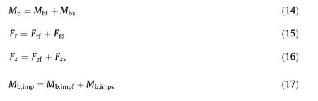
Since the validity of simulation has been verifed by the good agreement of the power number,dimensionless shaft bending moment and its relative standard deviation compared to the experiment,the following analyses focus on the coupling simulation results,including shaft bending momentMb, and loads acting on impeller(including impeller lateral forceFr, impeller axial forceFz,and bending moment on impellerMb,imp).The relations between the four kinds of loads are given by Eqs.(5)and(6)and all of these loads can be divided into fluid and structural components,which could not be distinguished in experiment,and are presented by subscript f and s respectively in Eqs.(14)-(17).
The fluid components of the impeller force in three direction vectors are given by Eqs.(18)-(20),respectively.Thex-andy-are the two components of impeller lateral force defined by Eq.(21)and thez-is the impeller axial force(the gravity of shaft and impeller is ignored in axial force).Besides of the dimensionless shaft bending moment defined by Eq.(12),the corresponding dimensionless coefficients of the rest three loads are given by Eqs.(22)-(24),respectively.

3.2.1.Shaft bending moment
Fig.7 shows the contour of the dimensionless coefficient α of shaft bending moment as a function of rotation speed and angle phase relative to baffle.The angle phase of0°,90°,180°and 270°mean that the center of a fixed blade coincides with the centers of four baffles,and forUb=1800 mm·g-1the fixed blade is the unbalanced.The overall downtrend of α with rotation speed is obvious just as shown in Fig.5.The α is higher at some particular phases and the phase intervals are about90°,especially forUb=0,which means the four times of speed frequency(4N)is a dominant frequency,named as blade passing frequency.However,some higher frequencies are still not clear in Fig.7.The periodic characteristic of αresults from its periodic fluid and structural components and will be discussed in detail in the following Sections 3.2.2 and 3.2.3.
The dimensionless coefficient α with rotation speed is shown in Fig.8.The resulting moment and the structural component forUb=1800 mm∙g are larger than those forUb=0 because the centrifugal force is much smaller for the perfectly balanced case.However,the fluid component changes slightly with rotation speed for two cases and both approximate 0.024.This is because the fluid motion is completely turbulent and the dimensionless fluid component is hardly related to the rotation speed.Besides,the fluid moment is hardly affected by the impeller mass imbalance,and thus the similar trend with rotation speed between resulting moment and its structural component.For low rotation speed,the structural component is larger than fluid component which means the structural component is dominant,but the difference is getting smaller with the rise of speed.However,if rotation speed continues increasing,the difference would get larger because the centrifugal force will be increasing and the structural component will increase since the speed frequency is getting close to the natural frequency of shaft impeller,and the self-excited resonance will take place.

Fig.8.Dimensionless coefficient of shaft bending moment.
3.2.2.Impeller lateral force
It is found that the dimensionless coefficientCrof impeller lateral force and its components shown in Fig.9 are similar to the dimensionless coefficient α of shaft bending moment in Fig.8.The resultingCrand its structural component decrease with the rise of rotation speed,while the fluid component remains constant.Such similar trend will be explained in the following Section 3.2.5.

Fig.9.Dimensionless coefficient of impeller lateral force.

Fig.7.Contour of dimensionless coefficient of shaft bending moment.
The frequency analysis is helpful to understand the fluctuating characteristics of impeller loads.There are mainly three groups of frequencies contributing to the fluctuation of impeller loads,which are the impeller speed frequency caused by the imbalance of stirred structure,the frequencies below impeller speed caused by macro-instabilities in the bulk flow and the frequencies higher than impeller speed which mainly consist of the blade passing frequency due to the pseudoturbulence originating from the trailing vortex behind impeller blades and the interaction between the blade and baffle.Furthermore,the multiple natural frequencies of stirring shaft could be stimulated.The behaviors of these frequencies depend on the operating conditions,the properties of fluid and the structure.The Yule-Walker autoregressive model is used to get the Power Spectral Density(PSD)of impeller loads in this paper.
The PSD of X-component of the impeller lateral structure and fluid force are shown in Figs.10 and 11,respectively.As shown in Fig.10 there are two evident peaks at each speed forUb=1800 mm·g-1and are marked by letter A and B respectively.The first peak marked by letter A is the impeller speed frequency caused by the impeller mass imbalance.The second peak marked by letter B locates around blade passing frequency,which is resulted from the unstable blade passing frequency of fluid motion near impeller.The blade passing frequency could transfer to the stirring structure via FSI and induce the vibration of stirring structure at this frequency.However,for the perfectly balanced impeller,the speed frequency disappears,and the blade passing frequency is the unique dominant frequency.
Compared to the PSD of lateral structure force,another two peaks are found in the PSD of lateral fluid force shown in Fig.11.The first peak marked by letter C locates at low frequencies,which is resulted from low-frequency macro-instability in the bulk flow in stirred vessel.The second peak marked by letter D locates around 0.51-0.52N,which could be related to the dynamic vortex shedding behind the blade.Similar to the PSD of structure force,the speed frequency disappears in perfectly balanced impeller as well,which indicates that dominant speed frequency is induced by the rotation of the unbalanced impeller and transfer to the fluid motion via the FSI.As a result,fluid pressure vibrates at speed frequency and therefore such dominant speed frequency will not be found,if impeller is perfectly balanced.
3.2.3.Impeller axial force
The dimensionless coefficientCzof impeller axial force is shown in Fig.12.The structural component of the axial force on impeller are nearly zero,the resultingCzand its fluid component are almost the same and remain a constant about 0.48,which indicates that the axial force on impeller almost comes from the fluid axial impact.In addition,the resultingCzand its two components are almost the same forUb=1800 mm·g-1andUb=0,indicating that theCzmatters little to the impeller mass imbalance.
The PSD of X-component of the impeller axial structure and fluid force are shown in Figs.13 and 14,respectively.In the PSD of axial structure force in Fig.13,the unique dominant frequency is blade passing frequency.Similar to the PSD of lateral fluid force in Fig.11,another dominant frequency locates at low frequencies marked by letter C is found in the PSD of axial fluid force in Fig.14.However,the speed frequency is not found in the PSD of both axial structure and fluid forces,even in the case of unbalanced impeller.This may be because that the impeller axial forces are much less sensitive to impeller mass imbalance than impeller lateral force,and the effect of impeller mass imbalance on the PSD of axial forces is too slight to be observed.Besides,we can see that the fluctuating intensity of impeller axial force around blade passing frequency is stronger than that of impeller lateral force,which demonstrates that compared to lateral force,the axial forces are more sensitive to the pseudo-turbulence originating from the trailing vortex behind blade.

Fig.11.PSD of X-component of the impeller lateral fluid force.

Fig.12.Dimensionless coefficient of impeller axial force.
3.2.4.Bending moment on impeller
The dimensionless coefficientCbof bending moment on impeller is shown in Fig.15.Similar to the dimensionless impeller lateral forceCrin Fig.9,the resultingCband its structural component decrease with the rise of rotation speed,while the fluid component remains constant about 0.0017 at each speed.Besides,t he effects of impeller mass imbalance on the resulting moment and its two components are negligible.Furthermore,the impeller is so rigid that the impeller axial vibration is much weaker and thus the lateral bending moment on impeller is much smaller.
3.2.5.Loads comparison

Fig.15.Dimensionless coefficient of bending moment on impeller.
As defined in Eqs.(5)and(6),the reactive shaft bending momentMbon the overhung point is a comprehensive effect of impeller lateral forceFr,impeller axial forceFzand bending moment on impellerMb,imp.The corresponding resulting dimensionless coefficient α,Cr,CzandCbare shown in Fig.16 to see the relative magnitude clearly.
It is clear that theCzis much larger thanCrsince the PBTD is an axial impeller rather than radial impeller in some extent,so the axial flow and the corresponding axial force on impeller are much larger than those of the lateral.However,the α is more closes toCrwhich indicating that the impeller lateral force is the key factor to shaft bending moment.This is because the bending moment on impeller is rather small and the effect of impeller axial force on shaft bending moment is rather weak since the force arm of impeller axial force to the overhung shaft is much smaller than that of impeller lateral force.Therefore,the dimensionless coefficientCrof impeller lateral force in Fig.9 is similar to the dimensionless coefficient α of shaft bending moment in Fig.8.

Fig.13.PSD of X-component of the impeller axial structure force.

Fig.14.PSD of X-component of the impeller axial fluid force.
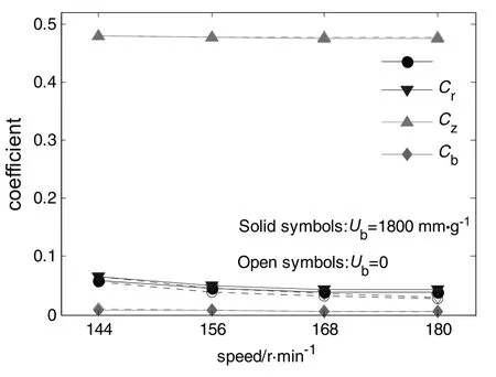
Fig.16.Dimensionless coefficient of four loads.
4.Conclusions
This paper reports a coupling simulation of the FSI in the stirred vessel agitated by a pitched blade turbine.The shaft bending moment,and the lateral forces,axial force and bending moment acting on impeller are discussed in detail.Particularly,the fluid and structural components from these loads are separated and extracted.
高校基层行政人员的职业生涯基本都是单调无趣的。这就要求高校在工作之余,为他们搭建其他兴趣交流平台,让他们在工作的同时学习到自身感兴趣的知识和能力,只有这种氛围持续存在,员工才会自我要求进步,只有进步才能推动工作的动力,提高工作效率。
Compared to the case of perfectly balanced impeller,the mass imbalance increases the shaft bending moment and lateral force on impeller,but the effects of it on the axial force and bending moment on impeller are negligible.The dimensionless coefficients of the fluid component of these four loads change slightly with rotation speed and hardly affected by the impeller mass imbalance.The shaft bending moment is a reactive load of other three loads acting on impeller,and mainly results from the impeller lateral force though the impeller axial force is much larger.
The fluctuating characteristics of impeller forces are induced by several dominant frequencies.The fluid component of impeller lateral force at the speed frequency is induced by the rotation of the unbalanced impeller via the FSI.However,the fluid component of impeller axial force at speed frequency disappears.The structural component of impeller lateral and axial force around blade passing frequency is induced by the trailing vortex behind blade via the FSI.The fluctuating intensity of impeller axial force around blade passing frequency is stronger than that of impeller lateral force.
Nomenclature
Cclearance of impeller off bottom of vessel,mm
Cbcoefficient of bending moment on impeller
Crcoefficient of impeller lateral force
Czcoefficient of impeller axial force
ddiameter of shaft,mm
Frimpeller lateral force,N
Fzimpeller axial force,N
fnthe first order laterally natural frequency,Hz
Hheight of liquid free surface,mm
Loverhung length of shaft,mm
Mbbending moment acting on shaft,N·m-1
Mb,impbending moment acting on impeller,N·m-1
Mtimpeller torque,N·m-1
mimpmass of impeller,kg
mshaftmass of shaft,kg
muunbalanced mass of impeller,g
Nrotation speed frequency,s-1
Nppower number
PSD power spectral density,N-2·m-2·s-1
ReReynolds number
RSD relative standard deviation
ruthe distance between the centers of additional weight and impeller geometry,mm
Tdiameter of stirred vessel,mm
Ubmass imbalance of impeller,mm⋅g-1
Wbwidth of baffle,mm
α coefficient of shaft bending moment
δ distance between centers of gravity and geometry,mm
μ dynamic viscosity of fluid,Pa·s
ρ density of fluid,kg·m-3
σ standard deviation of shaft bending moment,N·m-1
Subscripts
f fluid
s structure
xxdirection
yydirection
zzdirection
Superscript
—time-averaged
[1]S.Roy,S.Acharya,M.D.Cloeter,Flow structure and the effect of macro-instabilities in a pitched blade stirred tank,Chem.Eng.Sci.65(2010)3009-3024.
[2]P.Hasal,I.Fort,J.Kratena,Force effects of the macro-instability of flow pattern on radial baffles in a stirred vessel with pitched-blade and Rushton turbine impellers,Chem.Eng.Res.Des.82(2004)1268-1281.
[3]K.V.Riet,W.Bruijn,J.M.Smith,Real and pseudo-turbulence in the discharge stream from a Rushton turbine,Chem.Eng.Sci.31(1976)407-112.
[4]R.Escudie,A.Line,Experimental analysis of hydrodynamics in a radially agitated tank,AICHE J.49(2003)585-603.
[5]X.H.Liu,Y.H.Bao,Z.P.Li,Z.M.Gao,J.M.Smith,Particle image velocimetry study of turbulence characteristics in a vessel agitated by a dual Rushton impeller,Chin.J.Chem.Eng.16(2008)700-708.
[6]D.E.Shi,Y.Y.Liang,A.Eaglesham,Z.M.Gao,Effect of the impeller imbalance on the bending moment acting on an overhung shaft in a stirred vessel,Chem.Eng.Res.Des.92(2014)2191-2200.
[7]N.R.Kippers,A.G.L.Holloway,Experiments on the whirling of pitched blade impellers in baffled mixing vessels,J.Fluid Struct.49(2014)29-52.
[8]D.E.Shi,T.Lu,A.Eaglesham,Z.M.Gao,Characteristics of the bending moment acting on an overhung shaft in a stirred vessel,Int.J.Chem.React.Eng.12(2014)135-150.
[9]G.L.Lane,G.D.Rigby,G.M.Evans,Pressure distribution on the surface of Rushton turbine blades-experimental measurement and prediction by CFD,J.Chem.Eng.Jpn34(2001)613-620.
[10]T.Berger,M.Fischer,K.Strohmeier,Fluid-structure interaction of stirrers in mixing vessels,Trans.ASME125(2003)440-445.
[11]T.Berger,K.Strohmeier,Numerical simulation of stirrer oscillations in consideration of fluid-structure-interaction and flexible restraint systems,Proceedings of the ASME Pressure Vessels and Piping Division Conference,AICHE J,Cleveland Ohio,2003 pp.
[12]K.M.Mohamed,A.G.Gerber,G.A.L.Holloway,Modelling of hydrodynamic forces on a whirling mixing vessel stirrer including fluid-structure interaction,Proceedings of the ASME Pressure Vessels and Piping Division Conference,J.Chem.Eng.Jpn,Prague,Czech Republic,2009 pp.
[13]G.C.Cudmore,A.G.L.Holloway,A.G.Gerber,Whirlinstability of a rotating impeller in a baffled mixing vessel,Proceedings of the ASME Pressure Vessels and Piping Division Conference,J.Chem.Eng.Jpn,Paris,France,2013(pp.).
[14]D.E.Shi,Z.Q.Cai,A.Eaglesham,Z.M.Gao,Coupling simulation of lateral fluid structure interaction in a stirred vessel with a Rushton turbine,J.Chem.Eng.Jpn48(2015)147-157.
[15]S.Karray,Z.Driss,A.Kaffel,H.Kchaou,M.S.Abid,Fluid-structure interaction in a stirred vessel equipped with a Rushton turbine,Int.J.Mech.Appl.2(2012)129-139.
[16]S.Karray,Z.Driss,A.Kaffel,H.Kchaou,M.S.Abid,Numerical simulation of fluidstructure interaction in a stirred vessel equipped with an anchor impeller,J.Mech.Sci.Technol.25(2011)1749-1760.
[17]Y.L.Young,Fluid-structure interaction analysis of flexible composite marine propellers,J.Fluids Struct.24(2008)799-818.
[18]C.Y.Khor,M.Z.Abdullah,F.C.Ani,Study on the fluid/structure interaction at different inlet pressures in molded packaging,Microelectron.Eng.88(2011)3182-3194.
[19]B.Landvogt,L.Osiecki,P.Patrosz,T.Zawistowski,B.Zylinski,Numerical simulation of fluid-structure interaction in the design process for a new axial hydraulic pump,Prog.Comput.Fluid Dyn.14(2014)31-37.
[20]C.H.Lim,M.Z.Abdullah,I.A.Azid,M.S.A.Aziz,Experimental and numerical investigation of flow and thermal effects on flexible printed circuit board,Microelectron.Reliab.72(2017)5-17.
杂志排行

Chinese Journal of Chemical Engineering的其它文章
- Bioregeneration of spent activated carbon:Review of key factors and recent mathematical models of kinetics
- CFD simulations of quenching process for partial oxidation of methane:Comparison of jet-in-cross- flow and impinging flow configurations☆
- Quantifying growth and breakage of agglomerates in fluid-particle flow using discrete particle method☆
- An integrated model for predicting the flame propagation in crimped ribbon flame arresters☆
- Assessment of k-ε models using tetrahedral grids to describe the turbulent flow field of a PBT impeller and validation through the PIV technique
- Super-hydrophobic and super-lipophilic functionalized graphene oxide/polyurethane sponge applied for oil/water separation☆