Proton Beam Generated by Multi-Lasers Interaction with Rear-Holed Target
2018-01-22PengYang杨鹏DaPengFan范大鹏andYuXiaoLi李玉晓
Peng Yang(杨鹏),Da-Peng Fan(范大鹏),and Yu-Xiao Li(李玉晓)
School of Physics and Engineering,Zhengzhou University,Zhengzhou 450001,China
1 Introduction
Proton beams generated in the laser-foil interaction can be applied at different fields of engineering,such as bench-top particle accelerators,new ignition scheme of inertial confinement fusion(ICF),medical isotope production,and tumor therapy,etc.[1−3]However,the actual proton beams generated in the experiments are not yet of sufficient quality for practical use.In recent experiments,high energy protons have been observed by the development of the ultra-short,ultra-intense laser technology.[4−5]But the system is very complex and the volume is very huge,which limit its application. Furthermore,with the development of the micro-nano fabrication technology,it is possible to improve proton beam quality by designing special target geometries.[6−7]To absorb more laser energy,various targets with tailored front surfaces have been designed,such as rippling front surface,[8]concave front surface,[9−10]nano-brush target,[11]and nanostriped target.[12]To suppress the proton beam divergence,various targets with tailored rear surfaces have been proposed,such as holed rear surface,[13−14]umbrella-like rear surface,[15]and funnel-shaped rear surface.[16]
During the past decades,some mechanisms for the generation of laser-driven proton beam have been proposed.For example,the target normal sheath acceleration(TNSA),[17]radiation pressure acceleration(RPA),[18]shock wave acceleration(SWA),[19]and so on.Among them,the TNSA is widely used,which is easier to be realizable experimentally.In this mechanism,a thin foil target is ionized after illuminating by a laser pre-pulse,and the plasma electrons are pushed forward by the ponderomotive force of the main-pulse,forming a hot electron cloud at the rear surface of target. This electric charge separation generates a strong electric field(the order of the sheath field is 1012V·m−1)which accelerates the protons.[20]The sheath field has been found to scaled asE∝(nhTh)1/2,wherenhis the hot electron number density andThis the hot electron temperature.Therefore,to enhance the sheath field,one can use ultra-intense lasers or longer duration laser pulses to increase the electron density at the rear of target.However,the lateral diffusion of electron cloud decreases the electron density and leads to the divergence of proton beam in transverse.Sonobeet al.concluded that the proton beam divergence can be suppressed when the target has a hole in rear.[21−22]The hole reshapes the electron cloud but reduces the electron density.Toncianet al.achieved simultaneous focusing and energy selection of laser-driven proton beams by using a hollow microcylinder which illuminated by an additional laser pulse.[23]However,the maximum proton energy was not improved.
In this work,we propose a scheme to increase the electron cloud density by using a rear-holed target,which irradiated by multi-lasers from three different directions.The maximum energy of proton beam is increased signi ficantly,and the divergence is suppressed.The paper is organized as follows.Targets and simulation parameters are described in Sec.2,results and discussion are presented in Secs.3 and 4,and conclusion is given in Sec.5.
2 Targets and Simulation Parameters
In the scheme we proposed,three lasers(I1,I2andI3)are used to illuminate a rear-holed target at the same time.The linearly polarized laser pulseI1ofxdirection incident normally onto the target front surface att=0 fs.At the same time,I2andI3(ydirection linearly polarized)irradiate normally onto the sidewall of hole,as shown in Fig.1.The laser peak intensities areI1=1.0×10²⁰W/cm2,I2=I3=1.0×1019W/cm2,respectively.All lasers have a Gaussian envelope,and the laser FWHM is 20 fs.The laser focal spot diameter(FWHM)areD1=3λ,andD2=D3= Δh,hereλ=1µm is the laser wavelength and Δh=h−1µm is the length of the sidewall.The width of the Aluminum target front layer is 5µm;the thickness of the front layer and the sidewall are both 1µm.The Hydrogen layer of 30 nm thickness covers the bottom of the hole,and the width is 3µm,which is the same with the diameter of the cylinder hole.
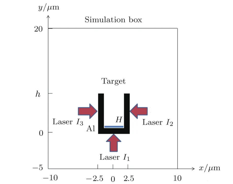
Fig.1(Color online)Location of the target in the simulation box.The calculation area is 20µm×25µm.Three lasers(I1,I2,and I3)are used to illuminate a rear-holed target at the same time.The H layer locates at the bottom of the hole.
Based on particle-in-cell(PIC)concept,[24−25]we developed a 2-dimensional PIC code ZZUPIC2D[26]to demonstrate the scheme.The simulation area is 20µm×25µm and free boundary conditions are used.The calculation mesh size is Δx= Δy=0.02λand the integration time step is Δt=0.0125T,hereTis the laser period.The ionization degree of the Al layer is 10,the density of ionized Al ions is 20nc,and the electron density is 200nc,herenc=meω20/4πe2stands for the critical density.The plasma density of theHlayer isnp=ne=nc.The initial electrons and ions temperature are set as 5.0 keV and 1.0 keV,respectively.The simulated particles mass ratios aremp/me=1836 andmAl/mp=27.The numbers of aluminum,hydrogen,and electrons micro-particles per cell are 24,22,and 52,respectively.
3 Effect of Multi-lasers on Electron Sheath and Proton Beam
A single laser target interaction(Case 1)which has only one laser(I1)to illuminate the target front surface is simulated as a comparison with the multi-lasers target interaction(Case 2),and the same targets of Δh=5µm are used in the two cases.Figure 2 shows the distributions of the longitudinal electrostatic fieldEygenerated by the hot electron cloud att=150 fs.Panels a-b correspond to Cases 1–2,respectively.The positiveEyaccelerates protons in the+ydirection.The maximum ofEyis in the center of the field,meaning that protons which locate in the center of the hole will be accelerated to the highest energy.Figure 3 demonstrates the number density distributions of hot electrons along the axis of hole(x=0µm)for Cases 1–2 at 150 fs.The definition of c is the number of electrons in a cell around a certain position.In Case 1,the electrons from the front layer are attracted by the positively charged sidewall,the edge of the electron cloud expands slightly in transverse and the hot electrons move into the sidewall gradually.The hot electrons,which moved into the sidewall,have no contribution to the proton acceleration.Therefore,the electron density decreases and the accelerating field is reduced.In Case 2,the hot electrons of sidewall are pushed into the hole and converge with those from the front layer,and the electron cloud density is increased.The maximum ofEyfield is 6.9 MV/µm in Case 2 and 3.8 MV/µm in Case 1,which shows significantly improvement of the accelerating field by using additional laser beamsI2andI3.
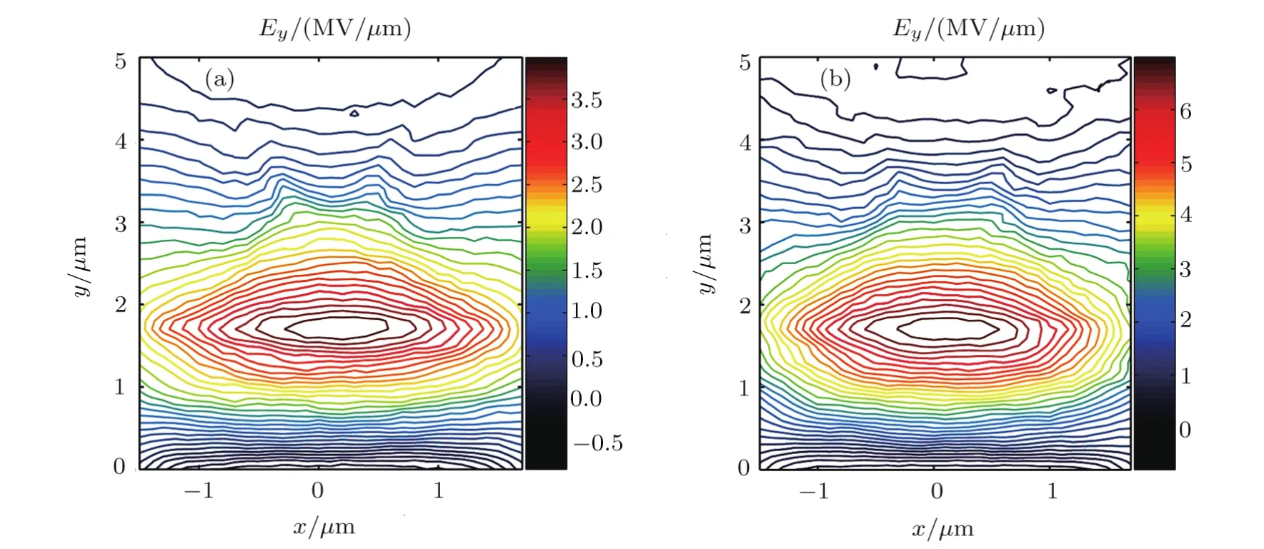
Fig.2 (Color online)The contour maps of longitudinal accelerating electric field generated by electron sheath in the single laser target interaction(a)and the multi-lasers target interaction(b)at 150 fs.The maximum of Eyis in the center of the field,meaning that protons,which locate in the center of the hole will be accelerated to the highest energy.
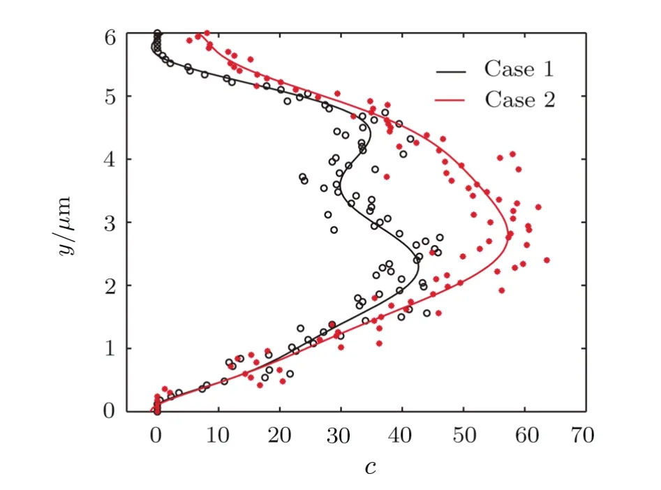
Fig.3 (Color online)Distributions of electron number density along the axis of hole(x=0 µm)for Cases 1–2. The electron density is significantly enhanced at y=1+Δh/2 in Case 2,which indicates that an electron cloud of greater density is formed.
The suppression of proton beam divergence in a rearholed target is due to the transverse electric field induced by the positively charged sidewall of hole,which does not exist in a plain target.Figure 4 shows the distributions ofExfield generated by the sidewall att=150 fs.Panels a-b correspond to Cases 1–2,respectively.The sign ofExindicates the direction of the field along thexaxis.When protons propagate toward the sidewall,their transverse velocity is reduced and eventually eliminated by theExfield.TheExfield in Case 2 is greater and wider than Case 1,indicating a better focusing effect on the protons.The proton energy spectra are given in Fig.5.The number of energetic protons from Case 2 is significantly more than that from Case 1 and the spectrum has a higher cutoff.The maximum proton energies of Case 1 and 2 are 14.3 MeV and 20.8 MeV,respectively.In Case 2,the widely distributedExfield has a remarkable effect on restricting protons,and a higher population of protons are confined transversely in the center of the hole,where the maximum of the accelerating field locates(Fig.2);these protons can be accelerated to higher energies than those locate at the edge of the sheath field.Consequently,higher populations of higher energy protons are produced in Case 2.However,theExfield in Case 1 is narrower and smaller than Case 2,which restricts less protons in the center of the accelerating field.Furthermore,in Case 1,the electric sheath has a smallerEyfield due to the sparse electron cloud.Therefore,much fewer energetic protons are produced in Case 1.
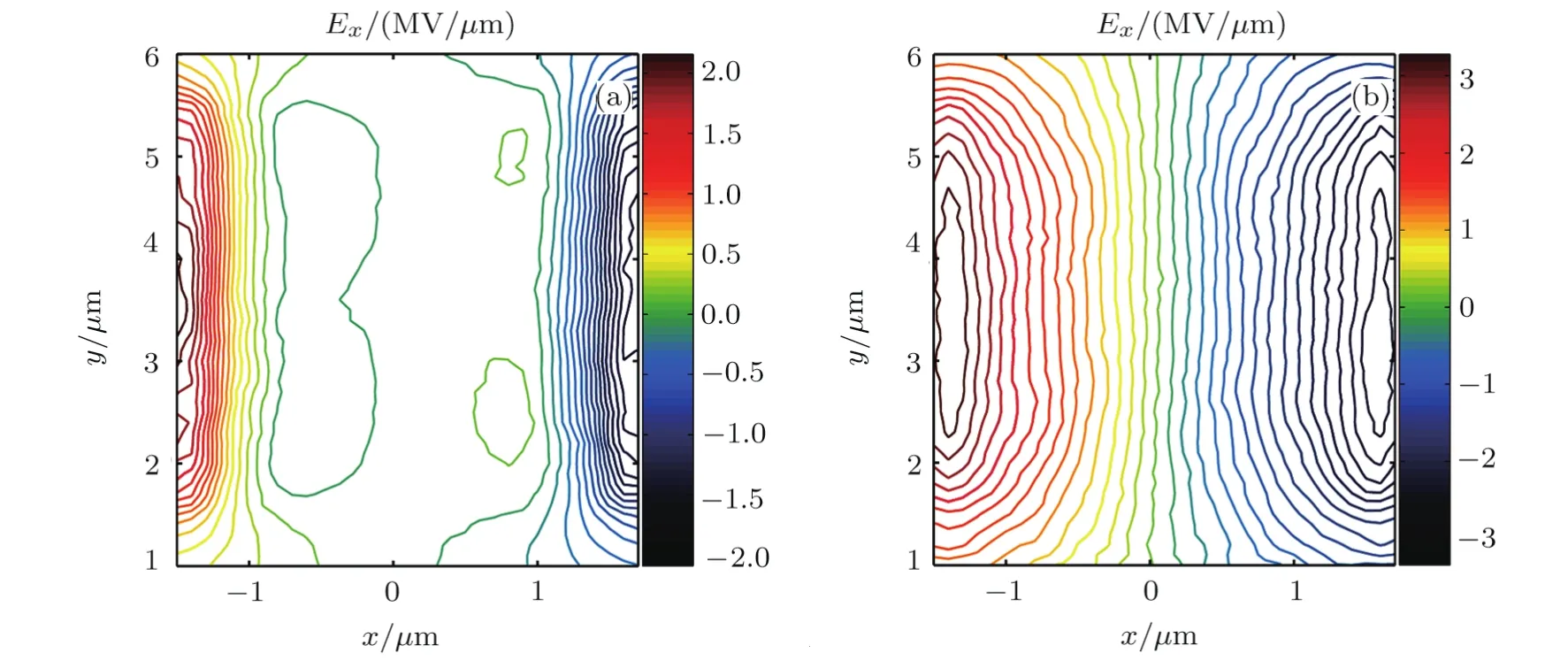
Fig.4(Color online)The contour maps of transverse electric field generated by the sidewall of hole in two cases at 150 fs.(a)In the single laser target interaction,the Ex field distribution is very narrow;(b)In the multi-lasers target interaction,the Ex field is greater and wider than Case 1,indicating a better focusing effect on the protons.
In Toncian’s research(Ref.[23]),the beam tailoring stage is decoupled from the acceleration stage,which results in a portion of the electrons failing to enter the cylinder,and can not converge with the electrons generated by the sidewall.The thickness of the cylinder sidewall is twice of the front layer,therefore the electric field is triggered by the CPA2laser pulse∼20 ps after the maximum protons(9 MeV)exit the cylinder.These explain why there is no increase in the maximum energy of protons in Toncian’s research.In the scheme we proposed,the cylinder is integrated with the front layer,and they have the same thickness,which ensure most of the hot electrons generated by the front layer can enter the cylinder(a part of electrons enter the hole directly,and the other part enters the side wall and then accelerates back to the hole by the transverse lasers),contribute to the increase of the electron number density and the peak proton energy.
The average divergence angles of the proton beams from two cases are calculated.The angle is defined by the following formula
hereNis the total number of protons;θi=arctan(Vx/Vy)is the divergence angle of one proton particle,whereVxandVyare the proton transverse and longitudinal velocity,respectively.The average divergence angles of Case 1 and 2 are 27.3°and 22.5°,respectively.It demonstrates that the transverse electric fieldExinduced by laserI2andI3has a remarkable effect on the suppression of proton beam divergence.
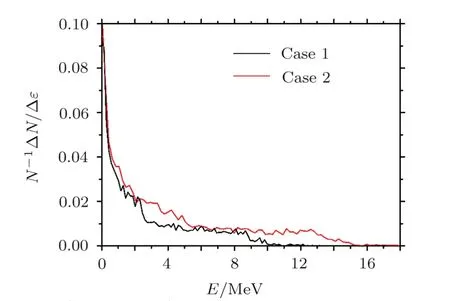
Fig.5(Color online)Energy spectra for the accelerated protons in two cases.The number of energetic protons from Case 2 is significantly more than that from Case 1 and the spectrum has a higher cutoff;for more protons are confined in the center of the hole,where protons can be accelerated to higher energies.
4 Dependence of Proton Beam on the Length of Sidewall
To investigate the dependence of proton beam on the length of sidewall,the interaction of multi-lasers with targets ranging in sidewall length(Δh)from 1µm to 10µm are simulated,respectively.Figure 6(a)shows the maximumExandEyof different targets,and Fig.6(b)demonstrates the characteristics(energy and divergence)of the accelerated proton beams.Since the laser focal spot diameter ofI2andI3is the same with Δh,theExfield decreases with increasing sidewall length.However,the divergence is optimized(22.3°)at Δh=4µm,because the shape of the electron cloud need to be controlled by a hole of sufficiently depth.The trend of the proton energy is the same as theEyfield,optimized both at Δh=3µm,and peaking at 23.7 MeV and 8.3 MV/µm,respectively.On the one hand,the hot electrons from the front layer of the target are mainly distributed between 1.5µm and 5µm in the longitudinal direction(Fig.3).On the other hand,the density of the side electrons peaking at the midpoint(y=1+Δh/2)of the sidewall.The convergence of the hot electrons is optimized when Δh=3µm,and theEyfield is maximized.
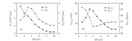
Fig.6 (Color online)(a)The maximum of Exand Ey field from targets with different sidewall length.(b)The characteristics(energy and divergence)of the accelerated proton beams from different targets.
The laser-proton energy conversion efficiency is also investigated(Fig.7).The conversion efficiency is defined byf=Eprotons/(EI1+EI2+EI3),which peaking at 3.9%when Δh=4µm(Case 4).Although theEyfield is the greatest when Δh=3µm(Case 3),the accelerating distance and time which protons experiencing in Case 4 are relatively longer than that in Case 3(due to the longer sidewall andExfield in Case 4),and the difference of theEyfields between Case 3 and 4 is small((8.3 and 7.9)MV/µm,respectively).As a result,the protons in Case 4 absorb more energy from lasers than Case 3.Consequently,for the parameters we use in the multi-lasers target interaction,the optimal length of sidewall is 4µm.The proton beam generated in the optimal target has the smallest average divergence angle(22.3°),and the highest laser-proton energy conversion efficiency(3.9%);the maximum proton energy is 22.9 MeV.We also calculate the energy conversion efficiency of proton production in the case of one pulse(laserI1).The energy conversion effi-ciencyEproton/EI1=4.1%,which is higher than that in the case of three pulseEproton/(EI1+EI2+EI3)=3.9%.However,in the case of three pulseEproton/EI1=4.7%,which means that the pulseI2andI3help transferring more energy ofI1to protons.
To investigate the dependence of proton beam on the width of the front layer,targets of front layer width from 5µm to 10µm are simulated.Figure 8 demonstrates the average divergence angle and the maximum energy of protons from different targets.The results show that the divergence angle increases and the maximum energy decreases with the width increasing.This is due to the increased width of the front layer that allows more hot electrons to propagate out of the cylinder.The electrons diverging outside of the cylinder take away a portion of the laser energy and are not used to accelerate protons.
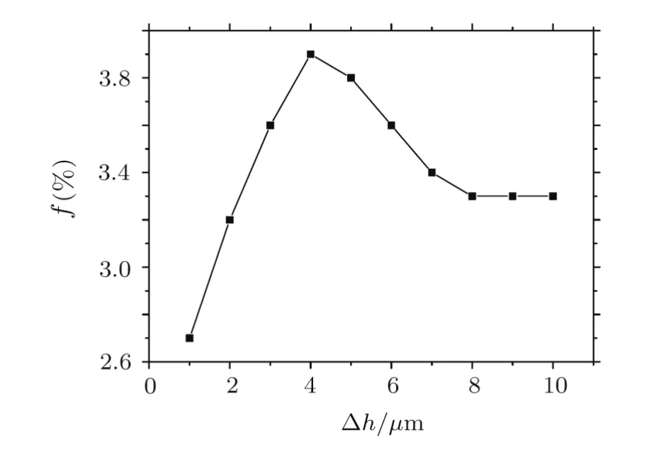
Fig.7 The laser-proton energy conversion efficiency of targets with different sidewall length.The peak of the efficiency is at Δh=4µm,indicating that the optimal length of sidewall is 4µm.
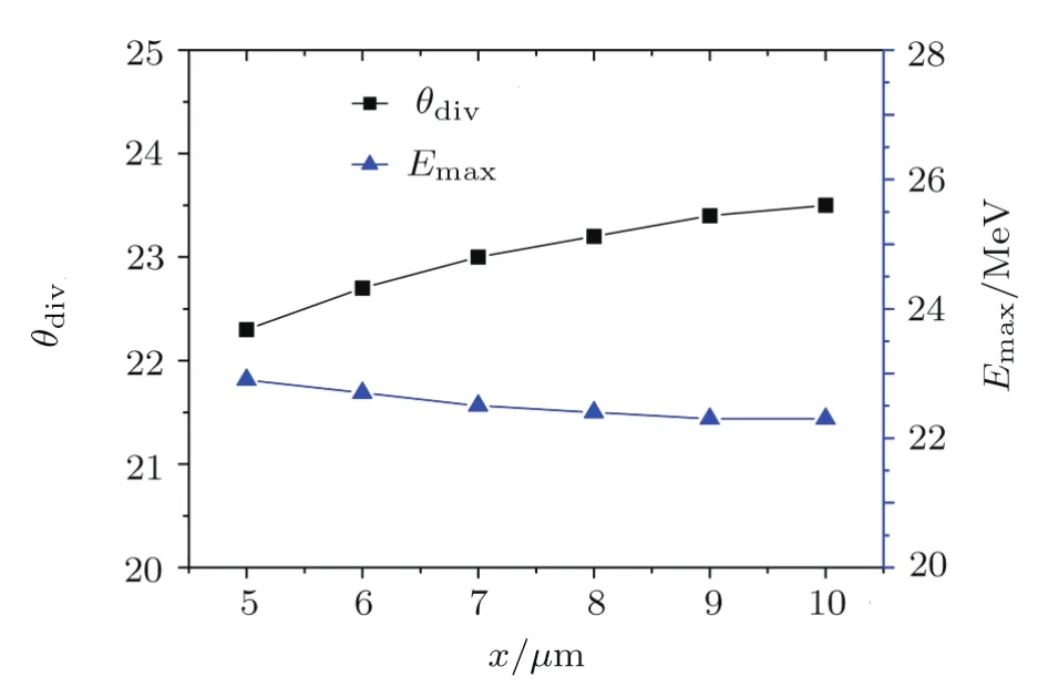
Fig.8 The average divergence angle and the maximum energy of protons from targets with different front layer width.As the increased width of the front layer allows more hot electrons to propagate out of the cylinder,the divergence angle increases,and the maximum energy decreases.
5 Conclusion
In summary,the interaction of multi-lasers and the rear-holed target is investigated by 2D PIC simulations.On the one hand,theExfield generated by the target sidewall is enhanced by the lasers irradiate from the side,and protons are focused transversely in the center of hole,where the maximum of the longitudinal sheath field locates.On the other hand,the hot electrons from the sidewall converge with those from the target front layer,and the density of the electron cloud is increased,promoting the accelerating field and the maximum energy of the obtained proton beams.Consequently,higher populations of higher energy protons are produced.The dependence of proton beam energy and divergence on the length of the sidewall is investigated in detail,and the optimal length of the sidewall is 4µm for the parameters we used in the simulations.The intensity of side laser is one order of magnitude smaller than the front laser,which is feasible in the experiment.The study demonstrated that the laser design is as important as the target design in laserdriven ion accelerator and the multi-lasers serves as a new method to enhance the proton acceleration in laser plasma interaction.
[1]K.W.D.Ledingham and W.Galster,New J.Phys.12(2010)045005.
[2]H.Daido,M.Nishuichi,and A.S.Pirozhkov,Rep.Prog.Phys.75(2012)056401.
[3]M.Mehrangiz,et al.,Commun.Theor.Phys.65(2016)761.
[4]M.E.Foord,et al.,Phys.Plasmas 19(2012)056702.
[5]J.Papeer,et al.,Appl.Phys.Lett.107(2015)124102.
[6]L.H.Cao,et al.,Phys.Plasmas 17(2010)043103.
[7]E.Schleifer,et al.,J.Phys.D 48(2015)085502.
[8]W.Q.Wang,et al.,Phys.Plasmas 21(2014)123112.
[9]L.H.Cao,et al.,Phys.Plasmas 18(2011)054501.
[10]M.A.Bake,B.S.Xie,S.Zhang,and H.Y.Wang,Phys.Plasmas 20(2013)033112.
[11]Z.Q.Zhao,et al.,Phys.Plasmas 17(2010)123108.
[12]J.W.Wang,et al.,Plasma Phys.Control.Fusion 57(2015)115009.
[13]T.P.Yu,et al.,Phys.Plasmas 16(2009)033112.
[14]K.D.Xiao,et al.,Phys.Plasmas 22(2015)093112.
[15]Y.Y.Ma,et al.,Phys.Plasmas 16(2009)034502.
[16]P.Yang,D.P.Fan,and Y.X.Li,Physica A 457(2016)183.
[17]S.C.Wilks,et al.,Phys.Plasmas 8(2001)542.
[18]H.B.Sang,S.Q.Deng,and B.S.Xie,Commun.Theor.Phys.59(2013)205.
[19]F.Fiuza,et al.,Phys.Rev.Lett.109(2012)773.
[20]E.d’Humiére,et al.,Phys.Plasmas 12(2005)062704.
[21]R.Sonobe,et al.,Phys.Plasmas 12(2005)073104.
[22]M.Nakamura,et al.,J.Appl.Phys.101(2007)113305.
[23]T.Toncian,et al.,Science 312(2006)410.
[24]G.M.Petrov and J.Davis,Comput.Phys.Commun.179(2008)868.
[25]G.M.Petrov and J.Davis,Phys.Plasmas 18(2011)073102.
[26]P.Yang,D.P.Fan,and Y.X.Li,Int.J.Mod.Phys.B 30(2016)1650045.
猜你喜欢
杂志排行

Communications in Theoretical Physics的其它文章
- Self-similar Solution of a Cylindrical Shock Wave under the Action of Monochromatic Radiation in a Rotational Axisymmetric Dusty Gas
- Advanced Study of Unsteady Heat and Chemical Reaction with Ramped Wall and Slip Effect on a Viscous Fluid
- Solutions to Forced and Unforced Lin–Reissner–Tsien Equations for Transonic Gas Flows on Various Length Scales
- Electrostatic Surface Waves on Semi-Bounded Quantum Electron-Hole Semiconductor Plasmas
- Quantum Spin Transport in Rashba Spin-Orbit-Coupled Graphene Nanoflakes∗
- Hypergeometric Series Solution to a Class of Second-Order Boundary Value Problems via Laplace Transform with Applications to Nanofluids