Interference Level Simulation and Analysis of the Power-frequency Parameter Measurement for UHVDC Transmission Lines
2018-01-09ZHANGQingqingWEIJingZHANGYanWANGHuajiaLIChangwei
ZHANG Qingqing,WEI Jing,ZHANG Yan,WANG Huajia,LI Changwei
(1.State Grid Shandong Electric Power Research Institute,Jinan 250003,China;2.State Grid Jining Electric Power Supply Company,Jining 272023,China;3.Shandong Zhongshi Yitong Group Co.,Ltd.,Jinan 250003,China)
Interference Level Simulation and Analysis of the Power-frequency Parameter Measurement for UHVDC Transmission Lines
ZHANG Qingqing,WEI Jing,ZHANG Yan,WANG Huajia,LI Changwei
(1.State Grid Shandong Electric Power Research Institute,Jinan 250003,China;2.State Grid Jining Electric Power Supply Company,Jining 272023,China;3.Shandong Zhongshi Yitong Group Co.,Ltd.,Jinan 250003,China)
By analyzing operating conditions of the parallel lines near the UHVDC transmission line,considering the geographical environment,phase sequence,tower type,wire erection mode,soil resistivity and other related factors,the interference level of the power-frequency parameter measurement for the Zhalute-Qingzhou UHVDC transmission line is calculated.The calculation results can help providing a theoretical guidance for the power-frequency parameter measurement scheme and guarantee the safety of personnel and equipment.
UHVDC;transmission line;power-frequency parameter measurement;interference level
0 Introduction
The±800 kV Zhalute-Qingzhou UHVDC transmission project is the first UHV DC transmission project inShandong,whichpassesthroughInnerMongolia,Hebei,Tianjin and Shandong,adding up to 3 provinces and 1 municipality.The length of the transmission line is 1 240 km,which is closely parallel to a number of 1 000 kV UHV AC lines and 500 kV EHV lines,and is parallel to±800kV Ximeng-Taizhou UHV DC transmission line within the same corridor in a long distance.
The induced voltage of the transmission lines can be up to tens of thousands of volts[1].Therefore,in the situation of large amount neighboring lines,high voltages,long parallel distance and small spacing between lines,the line parameter tester and the testing equipment of±800 kV Zhalute-Qingzhou UHVDC transmission are facing severe challenges.In order to develop a scientific DC transmission line parameter test scheme and guarantee the safety of UHVDC transmission line parameter testers and test equipment,it is necessary to understand the interference level in the first step before site operation.
By analyzing of the design data of the±800 kV Zhalute-Qingzhou UHVDC transmission line and its adjacent lines,the interference level of the ±800 kV Zhalute-Qingzhou UHVDC transmission line was simulated and analyzed before the test,which provides significant technical support for the scheme establishment of safety measurement and company outage.
1 Distribution of the Adjacent Lines of the UHVDC Transmission Lines
There are 4 main lines that are parallel to the Zhalute-Qingzhou UHVDC transmission line,including the±800 kV Ximeng-Taizhou UHVDC transmission line,the 1 000 kV Mengxi-Tianjin Nan UHVAC transmission line,the 1 000 kV Ximeng-Shandong UHVAC transmission line,500 kV Binyou I,II EHVAC transmission lines.
The parallel distribution situation of the±800 kV Zhalute-Qingzhou UHVDC transmission line with its adjacent UHVDC lines are shown in Table 1.The parallel distribution situationof its main adjacent AC lines are listed in Table 2.

Table1 The parallel distribution of the±800 kV Zhalute-Qingzhou UHVDC transmission line

Table2 TheparalleldistributionofthemainadjacentAClines of the±800 kV Zhalute-Qingzhou UHVDC transmission line
2 Simulation
2.1 The main parameters of the line
The wire type of the±800 kV Zhalute-Qingzhou UHVDC transmission line is 8 ×JL1 /G3A-1250 /70 and 8×JL1/G2A-1250/70.The split distance of the 8×JL1 /G3A-1250 /70 wire is 550 mm,DC resistance is 0.023 Ω /km.The split distance of the 8 ×JL1 /G2A-1250/70 wire is 550mm,DC resistance is 0.02291Ω /km.Oneground wiretypeisJLB20A-150,theDC resistance is 0.580 7 Ω /km.the other ground wire type is OPGW-150,the DC resistance is 0.558 Ω /km.The soil resistivity is 2.83~5 580 Ω·m.
2.2 Simulation and modeling method
Parallel line induced voltage calculation applies the method of modeling and simulating the AC and DC part separately.The influence caused by the interaction of all the AC lines is considered in the AC induced voltage modeling and simulation.The DC induced voltage modeling and simulation applies the same principle.
The simulation of the induced voltage uses the segmentation modeling method.The geo-environment along the transmission line,phase sequence,tower type,lead-erection mode,soil resistivity and other factors are comprehensively considered.
The operation conditions of the parallel operating line is simulated using the power flow and terminal voltage[2].
The voltage difference between the head and the end of the line should be considered in the simulation.Induced voltage observation devices model are applied at both ends of the line.
Due to the large cross-over angle of the adjacent spanned lines,its impact on the UHV transmission line is not considered[3].
The calculation and simulation method of the AC induced voltage is detailed in reference[4-5].In the calculation of the DC induced voltage,the distance between polar conductors of the Zhalute-Qingzhou UHVDC transmission line is 18~22 m.The line uses the Bergeron model.The detailed line model is illustrated in Fig.1,the model for the induced voltage calculation of the DC line is illustrated in Fig.2.

Fig.1 The model of the DC transmission line
3 Calculation Results and Analysis
3.1 Calculation results
According to the simulation results,the calculation results of induced voltage of the Zhalute-Qingzhou UHVDC transmission line are shown in Table 3~4.(Since the electromagnetic induced voltage is much smaller than the electrostatic induced voltage[4],the influence of electromagnetic induced voltage is not considered in the calculation).

Table 3 The calculation value of the AC induced voltage before parameters test kV

Table 4 The calculation value of the DC induced voltage before parameters test kV
3.2 Calculation results analysis
It can be seen from Table 3 and Table 4 that the DC induced voltage of Zhalute-Qingzhou UHVDC transmission line is very large,the maximum value of Zhalute side can reach 40,000 volts,and the maximum value of Qingzhou side can reach 60000 volts,which will cause great potential risks to the testers and the testing equipment.Therefore,the company outage scheme of the Zhalute-Qingzhou parallel DC line before the testing work is considered,and the simulation ofthecompanyoutage schemeisconducted,the detailed results is listed in Table 5.

Table 5 The calculation value of the accompany outage DC line kV
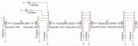
Fig.2 The model for the induced voltage calculation of the DC transmission line
It can be seen from Table 5 that stop the operation of a single line of the positive or negative pole of Xitai line (single pole operation) will cause a greater induced voltage value.In order to meet the needs of the field test,both lines of the positive and negative pole should quit from operation.
4 Conclusions
This paper simulates the interference level before the UHVDC line parameter testing by modeling and simulation,and provides theoretical guidance for the formulation of safety measures,safety equipment deployment,and the establishment of the company outage scheme.
According to the analysis of the simulation results,the DC induced voltage of the±800kV Zhalute-Qingzhou UHV line can reach 46.94 kV when the±800 kV Xitai line is operating with no load,and the AC induced voltage is over 2 000 V.Thus the main problem in line parameter testing is the high DC induced voltage.The connection and removal of the test lines and the frequent operation of switches during the line parameter testing procedure bring the risk of electric shock.
Therefore,it is necessary to stop the operation of the ±800 kV Ximeng-TaizhouUHVDC line.After the accompany outage,DC induced voltage will be reduced to a very smallvalue,which meets the testing requirements,and the operation of both poles should be stopped.According to the simulation results,the single pole operation will increase the induced voltage of the Zhalute-Qingzhou UHV line.
Reference
[1]LIU Haojun,YAN Guozeng,WANG Shaohua.Analysis of Electrostatic Induced Voltage on 1 000 kV Wannan-Zhebei UHV AC Transmission Line[J].High Voltage Engineering, 2015, 41(11):3687-3693.
[2]GUO Zhihong,YAO Jinxia,CHENG Xueqi,et al.Study and Measurement of Induced Voltage and Current for 500 kV Doublecircuit Line on Same Tower[J].High Voltage Engineering,2006,32(5):11-14,50.
[3]WANG Shaohua,HU Wentang,ZOU Guoping,et al.Influence of Adjacent Transmission Lines on Power Frequency Parameter Measurement for Anhui-to-East UHV Transmission Line [J].Power System Technology,2014,38(5):1 163-1 168.
[4]ZHANG Qingqing,WEI Jing,ZHANG Gaofeng,et al.Interference Level Calculation and Measurement of UHV Transmission Line Frequency Parameters Test[J].Shandong Electric Power,2016,43(12):12-14,33.
[5]ZHAO Songtao.Simulation of electromagnetic induction between parallel AC and DC Transmission lines[D].Baoding:North China Electric Power University,2006.
特高压直流输电线路工频参数测试干扰水平仿真分析
张青青1,韦 景2,张 岩1,王华佳1,李昌卫3
(1.国网山东省电力公司电力科学研究院,山东 济南 250003;2.国网山东省电力公司济宁供电公司,山东 济宁 272023;3.山东中实易通集团有限公司,山东 济南 250003)
通过分析特高压直流输电线路并行线路运行工况,综合考虑输电线路沿线地理环境、相序、塔型、导线架设方式、土壤电阻率等因素,对扎鲁特—青州特高压直流输电线路工频参数测试的干扰水平进行仿真计算,为特高压直流输电线路工频参数测试方案制定提供参考,保障了该线路工频参数测试人员及设备的安全。
特高压直流;输电线路;工频参数测试;干扰水平
TM744
A
1007-9904(2017)12-0012-04
date:2017-09-20 ZHANG Qingqing(1984),
M.Sc.Degree in Electrical Engineering from Xi'an Jiaotong University.She’s currently an engineer of State Grid Shandong Electric Power Research Institute.Her research interests include power quality problems and transmission line parameter measurement.