Matching mechanism analysis on an adaptive cycle engine
2017-11-20ZhengJunchaoChenMinTangHailong
Zheng Junchao,Chen Min,Tang Hailong
School of Energy and Power Engineering,Beihang University,Beijing 100083,China
Matching mechanism analysis on an adaptive cycle engine
Zheng Junchao,Chen Min,Tang Hailong*
School of Energy and Power Engineering,Beihang University,Beijing 100083,China
Adaptive cycle engine;Matching relationship;Matching mechanism;Performance;Variable geometries
As a novel aero-engine concept,adaptive cycle aero-engines(ACEs)are attracting wide attention in the international aviation industry due to their potential superior task adaptability along a wide flight regime.However,this superior task adaptability can only be demonstrated through proper combined engine control schedule design.It has resulted in an urgent need to investigate the effect of each variable geometry modulation on engine performance and stability.Thus,the aim of this paper is to predict and discuss the effect of each variable geometry modulation on the matching relationship between engine components as well as the overall engine performance at different operating modes,on the basis of a newly developed nonlinear component-based ACE performance model.Results show that at all four working modes,turning down the high pressure compressor variable stator vane,the low pressure turbine variable nozzle,the nozzle throat area,and turning up the core-driven fan stage variable stator vane,the high pressure turbine variable nozzle can increase the thrust at the expense of a higher high pressure turbine inlet total temperature.However,the influences of these adjustments on the trends of various engine components’working points and working lines as well as the ratio of the rotation speed difference are different from each other.The above results provide valuable guidance and advice for engine combined control schedule design.
1.Introduction
For the purpose of obvious reduction on R&D cost and cycle,design objectivesinclude all-weather,long-range,multimission,and so on for next-generation affordable aircraft.These design objectives lead to new requirements on aircraft engine design.On one hand,a newly designed engine should have turbojet features such as higher specific thrust in order to qualify forthruststringentmissionssuch asnonaugmented supersonic cruising and transonic climbing.On the other hand,it should also have the turbofan feature of lower specific fuel consumption to compete in fuel cost missions such as long-range reconnaissance.Clearly,to achieve these conflicting goals in an engine,a variable cycle engine1is undoubtedly an ideal propulsion device.
As a new concept of variable cycle engine,an ACE consists of a typical double-bypass VCE(variable cycle engine)2surrounded by a third bypass duct(shown in Fig.1).3The third bypass duct contains a row of variable inlet guide vanes and a single compression stage through extending one row of main fan blades into the stream.In essence,it is a triple-bypass VCE.It contains four different operating modes through different combined modulations of several variable geometries while a VCE contains double modes.4When both the third bypass and the second bypass are open,it operates at a triple-bypass mode named Mode M3.When the third bypass is closed while the second bypass is open,it operates at a double-bypass mode named Mode M2.On the contrary,if the third bypass is open while the second bypass is closed,it operates at another different double-bypass mode named Mode M13.When neither the second bypass nor the third bypass is open,it is called one-bypass mode named Mode M1.5When an ACE operates at Mode M1 or Mode M13,the third bypass is just open a little which guarantees the flow compatibility and contributes little to the power-balance.The Flade(fan on blade)is regarded as being closed.The gas paths of an ACE at variable modes are shown in Fig.2.
Owning to the complexity of an ACE which has three bypasses,the split ratio is more proper than the bypass ratio for their definitions.
The first bypass split ratio is defined as below:

whereB1is the first bypass split ratio,Wa24(kg/s)is the first bypass air flow,andWa23(kg/s)is the HPC(high pressure compressor)air flow.
The second bypass split ratio is defined as below:
whereB2is the second bypass split ratio,Wa22(kg/s)is the second bypass air flow,andWa21(kg/s)is the CDFS(core driven fan stage)air flow.
The third split bypass ratio is defined as below:
whereB3is the third bypass split ratio,Wa12is the third bypass air flow,andWa2(kg/s)is the fan air flow.
Through the combined modulation of various variable geometries,an ACE has four different working modes alternatives to guarantee superior performance along a wide flight regime.The available variable geometries are shown in Fig.3.It contains these variable geometries including the CDFS variable stator vane(VSVCDFS6),the Flade variable stator vane(VSVFlade7),the HPC variable stator vane(VSVHPC),the HPT (high pressure turbine)variable area nozzle(VANHPT),the LPT(low pressure turbine)variable area nozzle(VANLPT),the front VABI(variable area bypass injector(Pro-VABI),the rear VABI(Rear-VABI),8and the nozzle throat section(A8).
With the support of the AETD(Adaptive Engine Technology Development)plan,ACEs have made great progress.The core engine of an ACE has been tested by GEAE(General Electric Aircraft Engine Group).9According to the public literature,3avoiding severe inlet spillage drag at a supersonic part-load operation and greater variable cycle characteristics are the two obvious advantages of ACEs compared to other traditional aero-engines.Specially,by allowing an engine to pass as much amount of air as possible at a part-load operation during supersonic cruise,an ACE can avoid severe inlet spillage drag compared to a typical VCE such as F120.10In addition,the alternatives of four different working modes can extend the range of engine bypass ratio variation enormously.These two advantages can only be demonstrated through proper combined variable geometries control schedule design.Thus,there is an urgent need to investigate the effect of each variable geometry modulation on engine performance and stability.Research on variable geometries of a turbofan engine has already been done.11However,little literature has been published on the understanding of components matching mechanisms of this ACE concept,which is essential to design a proper control schedule to release the performance potential of ACEs around a wide flight regime.
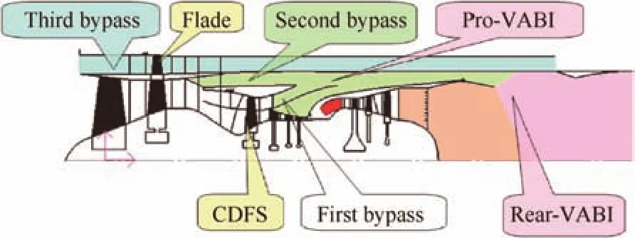
Fig.1 Configuration of an adaptive cycle engine.

Fig.2 Flow path characteristics of an ACE at variable modes.
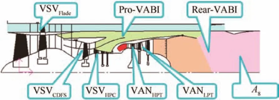
Fig.3 Variable geometries of an ACE.
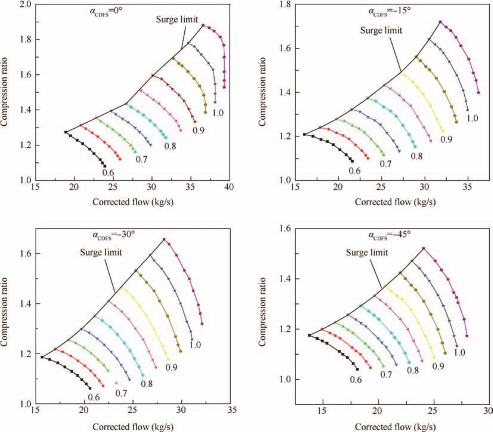
Fig.4 Multi-angle characteristic maps of the CDFS.

Fig.5 Introduction of the related sections of an ACE.
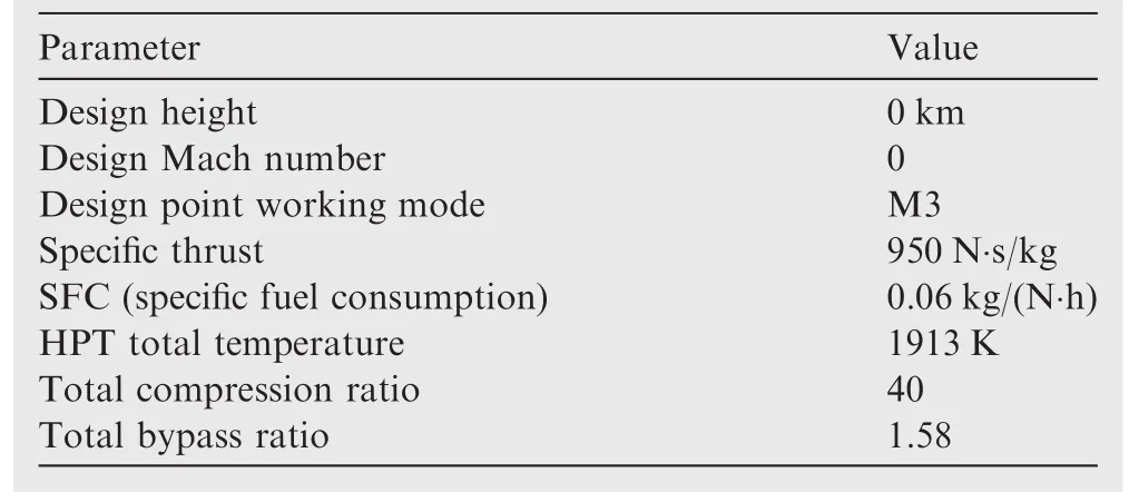
Table 1 Related design point parameters.
Therefore,this paper aims at investigating the effect of each variable geometry modulation on the matching relationship between engine components as well as the overall engine performance at different operating modes.To analyze the effect of geometries scrupulously,ACE performance modeling is required to be developed firstly.
In this article,Section 1 gives a brief introduction on the background of ACEs.The section following it presents the ACE performance model.Section 3 discusses the effects of geometric variations at various modes of an ACE via a combination of theoretical analysis and calculation results verification via the ACE performance model.The final section draws the conclusions.
2.ACE performance model
Every component has one inlet section and one exit section.The related sections of an ACE are shown in Fig.5.At each section,an array of gas thermodynamic parameters in terms of pressure,temperature,velocity,area,mass flow,fuel-air ratio,enthalpy,entropy,etc.,are defined and used to pass information from one component to the next.These thermodynamic and performance parameters can be solved numerically when the control schedule is given.More details about general engine performance simulation can be found in the literature.12,13The modeling theory and method have been tested and verified accurately.14,15
Gas property differences,caused by the variations of gas ingredients,ambient temperature,and ambient humidity,are considered in the model.Other factors are also taken into account,such as the effect of altitude,Mach number,extraction and return of cooling air,power set aside for aircraft accessories,and so on.
The performance model mainly has two modules,which are the design module and off-design module.First of all,the design module mainly works out engine key geometric parameters and design point thermal dynamic parameters as well as performance parameters.Then,the off-design module evaluates the performance at other operating conditions and working modes.
Compared to a typical turbofan performance model,its differences are listed below:
(1)It contains 4 different working modes;
(2)The LP(low pressure)power-balance equation includes the term of the Flade consumed compression power;
(3)There are two static pressure balance equations in both the front flow mixed zone and the rear flow mixed zone;
(4)It contains more variable geometries including VSVFlade,VSVCDFS,VSVHPC,VANHPT,VANLPT,andA8(Pro-VABI and Rear-VABI are not discussed here).
2.1.Design performance parameters
To calculate the engine design performance,specific parameters such as the engine cycle parameter and components parameters should be given in advance.Some important design parameters at the design point are shown in Table 1.
2.2.Solving working point
As to the off-design performance modeling,the related gas components are coupled together through the balance equations.The equations considered included the power-balance equation for each rotor,the flow compatibility equation between connected gas components,and the static pressure balance equation at the mixing surface boundary of the duct and core flows.These equations in essence are implicit and nonlinear.The number of balance equations varies with different engine constructions.For example,a single-spool turbojet has 3 equations;a double-spool turbofan has 6 equations;while an ACE has 7 equations.It must also be noted that these equations of an ACE vary with different working modes.The difference is shown as below.
2.2.1.Balance equations of an ACE on Mode M1
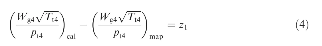
a.Flow compatibility equation of the HPT:
b.Power-balance equation of the HP(high pressure)rotor:

wherePHPT(kW)is the HPT power,gmHis the high pressure rotor mechanical efficiency,PHPC(kW)is the HPC power,PCDFS(kW)is the CDFS power,andz2is the second residual value.
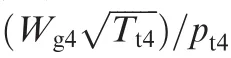
c.Flow compatibility equation of the LPT:
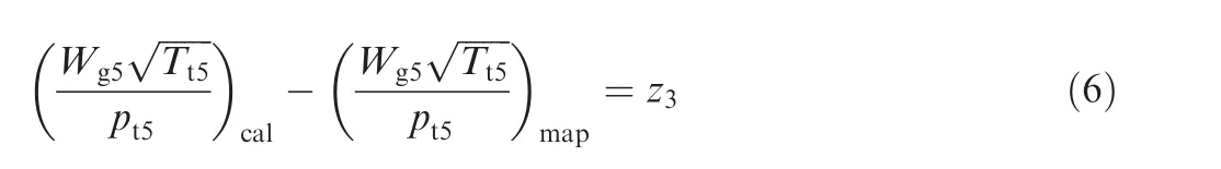
whereWg5(kg/s)is the LPT inlet gas flow,Tt5(K)is the LPT inlet total temperature,pt5(Pa)is the LPT inlet total pressure,

d.Power-balance equation of the LP rotor:

wherePLPT(kW)is the LPT power,gmLis the low pressure rotor mechanical efficiency,PFan(kW)is the fan power,andz4is the fourth residual value.When an ACE works at Mode M1,the power of the Flade can be neglected relative to that of the fan.
e.Flow compatibility equation of the CDFS:

wherez5is the fifth residual value.
f.Static pressure balance equation of the Rear-VABI:

g.Flow compatibility equation of the nozzle throat section area:

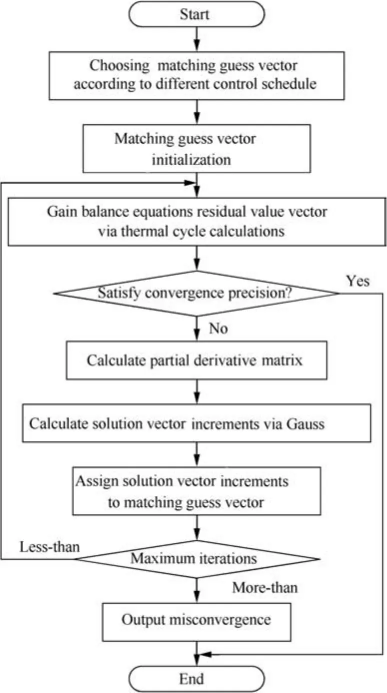
Fig.6 Off-design performance calculation logic flow chat.
whereA8(m2)is the nozzle throat section area,z7is the seventh residual value.
2.2.2.Balance equations of an ACE on Mode M13
When an ACE works at Mode M13,the third bypass is open and the Flade operates.The power-balance equation of the LP rotor is different from that at Mode M1(shown in Eq.(11)).The other equations are consistent with the ones at Mode M1:

wherePFlade(kW)is the Flade power.
2.2.3.Balance equations of an ACE on Mode M2
When the second bypass is open at Mode M2,the flow compatibility equation of the CDFS at Mode M1 changes into the static pressure balance equation of the Pro-VABI at Mode M2.The other equations are also consistent with the ones at Mode M1:

whereps22(Pa)is the second bypass outlet static pressure andps24(Pa)is the first bypass outlet static pressure.
2.2.4.Balance equations of an ACE on Mode M3
算法中使用双口RAM对参数进行存储,寄存器用于流水线中的数据缓存,通过表1可以看出本文提出的算法占用硬件资源极少,有效地节约了硬件成本。
When both the second and third bypasses are open at Mode M3,the power-balance equation of the LP rotor and the flow compatibility equation of the CDFS at Mode M1 change as shown in Eq.(11)and Eq.(12),respectively.Other equations are consistent with the ones at Mode M1.
During the off-design performance simulation,maps based on parameter groups represent each engine rotated component.For given flight conditions and engine control schedule,such as 100%power,the operating point on each component map is also unique,being dependent on the maps of the components that it is either connected or matched to.The search for the engine match operating point is highly iterative.It requires successive ‘guesses’of the operating point on some component maps.For each engine,there are several matching guesses and an equal number of balance equations.Values of these guesses are updated as iterations continue until all the balance equations are satisfied.Once the iterations are complete,overall cycle parameters such as thrust or fuel flow can be easily worked out.The gas thermodynamic parameters can also be derived,such as gas temperature,pressure,mass flow,and enthalpy,in the inlet and outlet of each engine component.
As to an ACE,the residual values of each balance equation form the residual value vector Z as follows:

In order to calculate the corresponding 7 equations,it needs the corresponding control schedule and the same number of matching guesses which form the matching guess vector.The matching guess vector X is

The residual value vector Z can be described as the implicit and nonlinear function of the matching guess vector X as follows:

As an ACE has four different working modes and greater variable cycle characteristics,its performance model affords variable control schedules to give a full play to the potential of the ACE.The available different main control schedules of an ACE are listed as below:
(1)LP relative speed to be kept consistent;
(2)HP relative speed to be kept consistent;
(3)LP corrected speed to be kept consistent;
(4)Total temperature at a related section such as the HPT inlet section to be kept consistent.

Supposing that thek-iteration has proceeded,thekiteration matching guessvectorXkand thek-iteration matching residual value vector Zkare already calculated,thek+1-iteration matching guess vector is

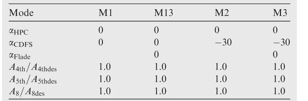
Table 2 Variable geometries’original values at various modes.

Table 3 Changes of VSVHPCat various modes.
The matrix A in Eq.(16)is a partial derivative matrix which is Jacobian as follows:

Then,thek+1-iteration matching guess should be substituted into Eq.(15)to proceed to thek+1-iteration calculation untiltheresidualvaluevectorsatisfiesthegiven convergence precision.The flowchart of the computational procedure is shown in Fig.6.
3.Effects of geometric variation at various modes of an ACE
In order to analyze the components matching mechanisms of an ACE at four different operating modes and the effects of variable geometries’modulations on the matching relationship,variable geometries analysis at various modes is done.In engineering practice,the 6 variable geometries(VSVFlade,VSVCDFS,VSVHPC,VANHPT,VANLPT,andA8)should be adjusted simultaneously to make the ACE work both in good performance and steadily.To study the influences of multivariable geometries,single-variable analysis should be done initially.This analysis is very important to design the control schedules of the ACE.With the help of the ACE performance model introduced above,variable geometries analysis can be done efficiently.The analytical method is the control variate method.6 variable geometries are analyzed on 4 working modes in this article.The 6 variable geometries have an original value on each working mode(shown in Table 2).When one of the 6 variable geometries is adjusted,the other variable geometries keep unchanged.
The working condition is set as 0 km andMa¼0,which is the design point’s working condition.The control schedule is to keep the LP speed constant as 1.0.
3.1.VSVHPCon different modes
When VSVHPCis adjusted,the other variable geometries remain fixed.The original and adjusted aHPCare shown in Table 3.Then,at each working mode,two working points named the original one and the adjusted one are simulated by the ACE performance model to investigate the VSVHPCeffect analysis.The histograms of related parameters of the ACE on different working modes are shown in Fig.7.The value of each parameter is the rate of relative change which is described as follows:

whereRis the rate of relative change,Yoriginalis the original value,andYadjustedis the adjusted value.
When the engine operates at Mode M1 and the LP speed is constant,a reduction of the HPC flow capacity by turning down VSVHPCcan increase the thrust at the expense of a higher HPT inlet total temperature.This reduction drives more air flowing into the first bypass,thus increasing the first bypass split ratio while decreasing the core flow.Then,a decreasing trend of the LP speed occurs because of the decline of the LPT work for a less core flow.Hence for a constant LP speed,more fuel should be injected.Further,the HPT inlet total temperature rises,leading to an increase of the HP speed.Increasing the HP speed improves the CDFS suction capacity and hence the air flow.However,as for the CDFS flow capacity,it is influenced by the HPC and the first bypass simultaneously.In this operating condition,the CDFS surge margin declines while the fan surge margin improves.
In Fig.7,F(N)is the thrust,Wf(kg/s)the fuel flow,Tt4(K)is the HPT inlet total temperature,n2is the high pressure rotor relative speed.
At Mode M13,the HPT inlet total temperature is higher and the thrust is larger than those at Mode M1 because of the Flade.The relative values of related parameters at Mode M13 versus Mode M1(described as Eq.(19))are shown in Fig.8.The remaining parameters at Mode M13 change similarly when compared to those at Mode M1.It is noteworthy that VSVHPCdoesn’t affect the Flade working point when the control schedule is to keep the LP speed constant.Hence,the Flade air flow,pressure ratio,and work parameters remain constant.

whereYM13is the Mode M13 value andYM1is the Mode M1 value.
At Mode M2,although the CDFS suction capacity increases,the fan flow capacity maintains constant due to the second bypass air flow split.In that case,the fan working point almost remains unchanged as well as the fan surge mar-gin for a constant LP speed.Moreover,the second bypass split ratio decreases as the CDFS air flow increases.The remaining parameters at Mode M2 change similarly when compared to those at Mode M1.
At Mode M3,the HPT inlet total temperature is higher and the thrust is larger than those at Mode M2 because of the Flade.The relative values of related parameters at Mode M3 versus Mode M2(described as Eq.(20))are shown in Fig.9.The remaining parameters change similarly when compared to those at Mode M2.
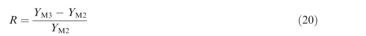
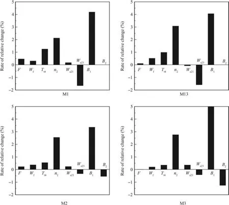
Fig.7 Related parameters of the ACE versus VSVHPC.
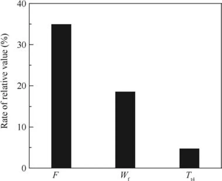
Fig.8 Related parameters at Mode M13 versus Mode M1.
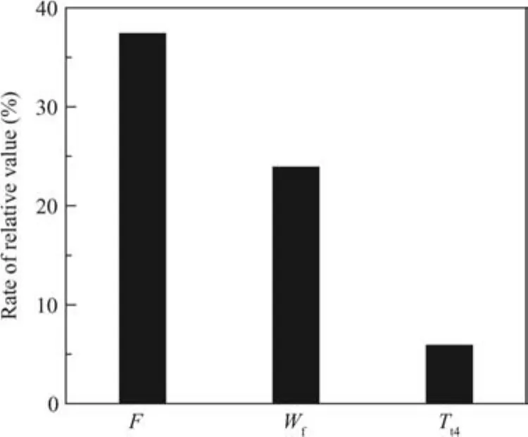
Fig.9 Related parameters at Mode M3 versus Mode M2.
whereYM3is the Mode M3 value andYM2is the Mode M2 value.
3.2.VSVCDFSon different modes
The original and adjusted values of VSVCDFSare shown in Table 4.The histograms of related parameters of the ACE on different working modes are shown in Fig.10.
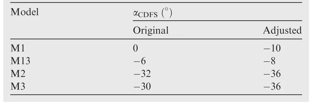
Table 4 Changes of VSVCDFSat various modes.
When the engine operates at Mode M1 and the LP speed is maintained constant,turning down VSVCDFSdecreases the HPT inlet total temperature,the thrust,the fan surge margin,as well as the CDFS surge margin,but increases the HPC surge margin.The relative changes of related surge margins which are the adjusted versus the original are shown in Fig.11.Directly,turning down VSVCDFSdecreases the CDFS flow capacity.The CDFS compression work drops when other parameters remain constant for a decrease of the CDFS flow capacity.Then,this drop increases the HP speed and hence the HPC suction capacity.As a result,there is more core flow driving the LPT.In this way,the LP speed tends to rise as the LPT output work improves.Hence,for a constant LP speed,fuel flow has to decrease,resulting in a decrease of the HPT inlet total temperature.According to the flow continuity relationship,the fan flow capacity drops a little for a decrease of the CDFS flow capacity.As for the fan,the working point moves up slightly along the referred speed line.The corrected flow of the fan decreases 0.08%,and the compression ratio increases 0.5%,which are not clear to be shown in Fig.10.
In Fig.11,SMFis the fan surge margin,SMCDFSis the CDFS surge margin,SMHPCis the HPC surge margin.
At Mode M13,the HPT inlet total temperature is higher and the thrust is larger than those at Mode M1 because of the Flade.At Mode M2,the fan working point almost remains unchanged as well as the fan surge margin for a constant LP speed.Meanwhile,the first bypass split ratio decreases as the CDFS air flow increases.The remaining parameters change similarly when compared to those at Mode M2.As for Mode M3,the HPT inlet total temperature is higher and the thrust is larger than those at Mode M2 because of the Flade.The remaining parameters change similarly when compared to those at Mode M2.
3.3.VSVFladeon different modes
Since the Flade is closed when the engine operates at Modes M1 and M2,this section only analyses the effect of VSVFladevariation at Modes M13 and M3.The original and adjusted values of VSVFladeare shown in Table 5.The histograms of related parameter of the ACE on different working modes are shown in Fig.12.
In Fig.12,pCDFSis the CDFS compression ratio,pHPCis the HPC compression ratio.
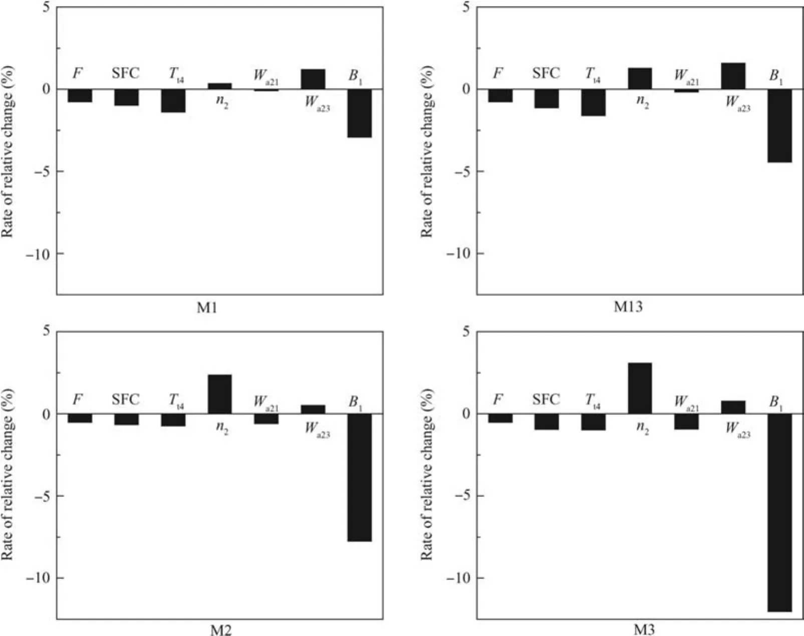
Fig.10 Related parameters of the ACE versus VSVCDFS.
When the engine operates at Mode M13 and the LP speed is maintained constant,turning down VSVFladedecreases the HPT inlet total temperature and the thrust,but the CDFS and the fan surge margin decrease a little.Directly,turning down VSVFladedecreases the Flade inlet flow and hence the Flade compression work.Then,the LP speed tends to rise up for less LP compression work.Thus for a constant LP speed,less fuel is injected.This results in declines of the HPT inlet total temperature and the HP speed.It follows that the HPC working point moves down along its working line.Further,a decrease of the HPC compression work occurs due to decreases of the HPC air flow and compression ratio.This drives more air to flow into the first bypass leading to an increase of the first bypass split ratio.Meanwhile,less fuel decreases the LPT expansion ratio.In that case,the LPT outlet pressure increases.The CDFS outlet back pressure also increases at rear-VABI.As a result,the CDFS compression ratio increases a little,but its flow capacity decreases a bit.According to the flow continuity relationship,the fan air flow decreases but its compression ratio increases.
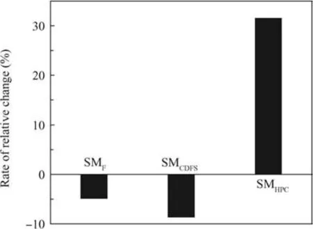
Fig.11 Related surge margins of the ACE versus VSVCDFS.
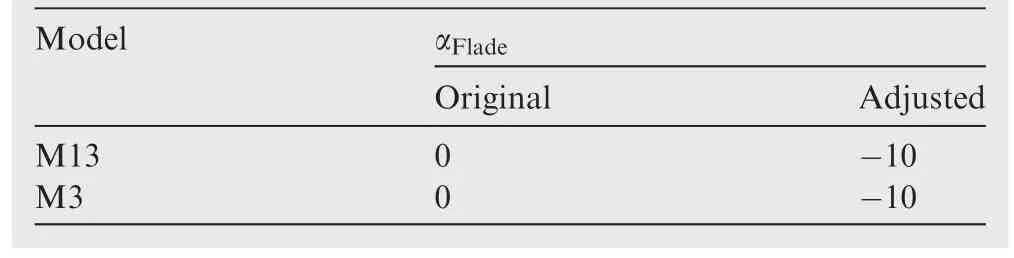
Table 5 The changes of VSVFladeat various modes.
At Mode M3,although the CDFS suction capacity increases,the fan flow capacity maintains constant due to the flow split effect of the second bypass air.Therefore,the fan working point almost remains unchanged as well as the fan surge margin when the LP speed is maintained constant.In the meantime,the second bypass split ratio increases for the same reason.The change of the first bypass split ratio is not obvious,since the CDFS and HPC flow capacities both decline.The other parameters change similarly when compared to those at Mode M13.
3.4.VANHPTon different modes
The original and adjusted values of VANHPTare shown in Table 6.The histograms of related parameter of the ACE on different working modes are shown in Fig.13.
When the engine operates at Mode M1 and the LP speed is maintained constant,turning up VANHPTcan increase the thrust at the expense of a higher HPT inlet total temperature and a lower fan surge margin(decreasing 13%).Initially,a decrease of the HPT expansion ratio occurs if VANHPTis turned up.It causes a decline of the HPT output work.Then,this decline breaks the HP work balance.As a result,the HP speed drops.The air flow and compression ratio of the HPC decrease as well as those of the CDFS.Meanwhile,the HPC suction capacity declines because of the dropping HP speed.In that case,the first bypass split ratio increases.The CDFS suction capacity also declines due to the decline of the HP speed.Thus,the fan flow capacity decreases but the fan pressure ratio increases according to the flow continuity relationship.Then the LP speed tends to drop down.Hence,for aconstant LP speed,more fuel has to be injected and the HPT inlet total temperature rises up.

Table 6 The changes of VANHPTat various modes.
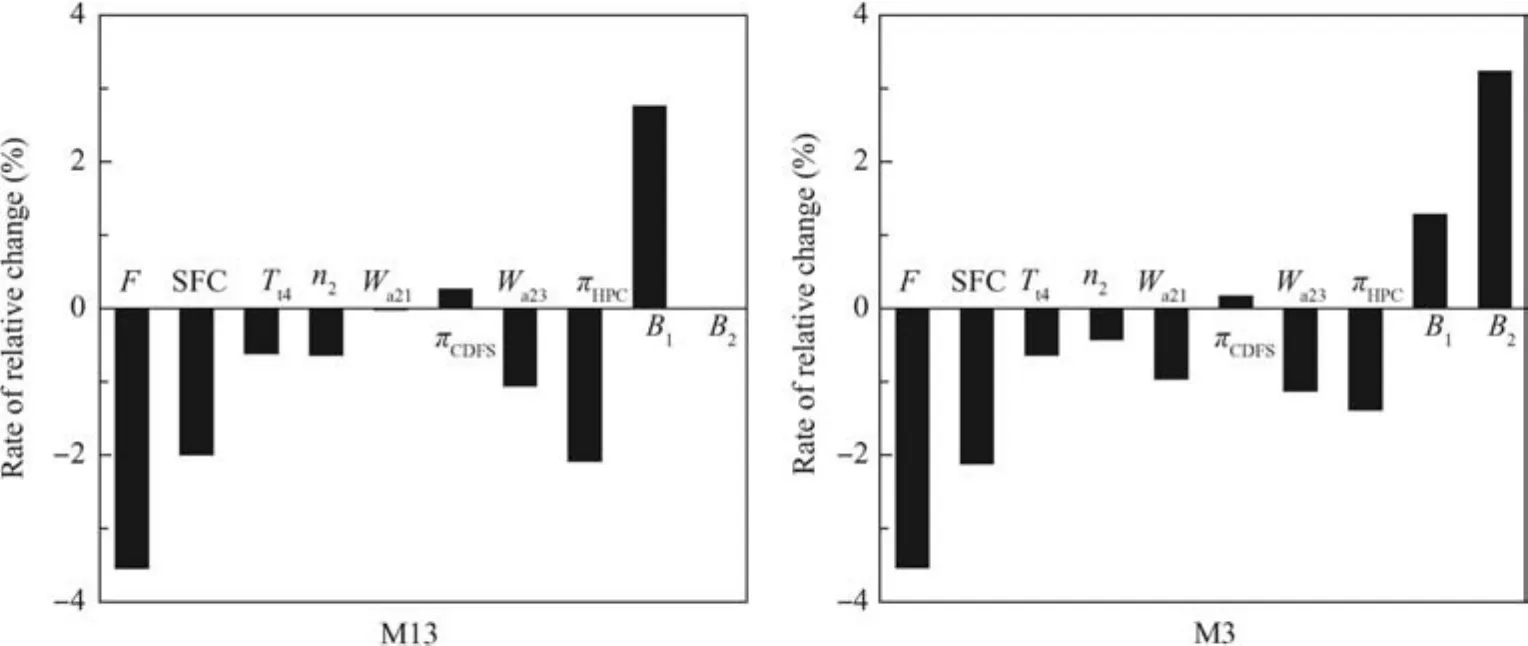
Fig.12 Related parameters of the ACE versus VSVFlade.
At Mode M13,the HPT inlet total temperature is higher and the thrust is larger than those at Mode M1 because of the Flade.At Mode M2,although opening the second bypass decreases the influence of the fan outlet flow capacity from the HP rotor,turning up VANHPTstill increases the fan outlet back pressure and decreases the fan surge margin.At Mode M3,the HPT inlet total temperature is higher and the thrust is larger than those at Mode M2.Compared to the other parameters at Mode M1,they change similarly at Modes M13 and M2.
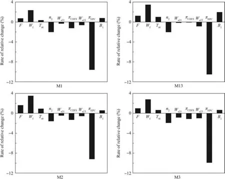
Fig.13 Related parameters of the ACE versus VANHPT.

Table 7 The changes of VANLPTat various modes.
3.5.VANLPTon different modes
The original and adjusted values of VANLPTare shown in Table 7.The histograms of related parameter of the ACE on different working modes are shown in Fig.14.
When the engine operates at Mode M1 and the LP speed is maintained constant,turning up VANLPTcan increase the ratio of the rotation speed difference,improve the fan and CDFS surge margins(shown in Fig.15),and decrease the HPT inlet total temperature and the thrust.Directly,turning up VANLPTleads to an increase of the HPT expansion ratio.This increase may improve the HPT output work.Then,the HP work balance is broken as a result that the HP speed tends to rise.The in fluence and the reason are shown as below:the flow capacity and compression ratio of the HPC increase;the CDFS flow capacity improves while the CDFS compression ratio deceases due to a decline of the CDFS outlet back pressure.As the CDFS compression ratio decreases,the fan outlet back pressure declines.Accordingly,a decrease of the fan compression ratio occurs.The LP speed tends to rise up as the fan compression work decreases.Hence,for a constant LP speed,less fuel should be injected,leading to a drop of the HPT inlet total temperature.The HPC working point moves down along its working line(shown in Fig.16).
At Mode M13,the HPT inlet total temperature is higher and the thrust is larger than those at Mode M1 because of the Flade.At Mode M2,the fan flow remains relatively constant when the second bypass is open.Less air flows into the first and second bypasses as the HPC and CDFS flow capacities improve which reduce the first and second bypass split ratio.Compared to the remaining parameters at Mode M1,they change similarly as at Modes M13 and M2.At Mode M3,the HPT inlet total temperature is higher and the thrust is larger than those at Mode M2 because of the Flade.

Fig.14 Related parameters of the ACE versus VANLPT.
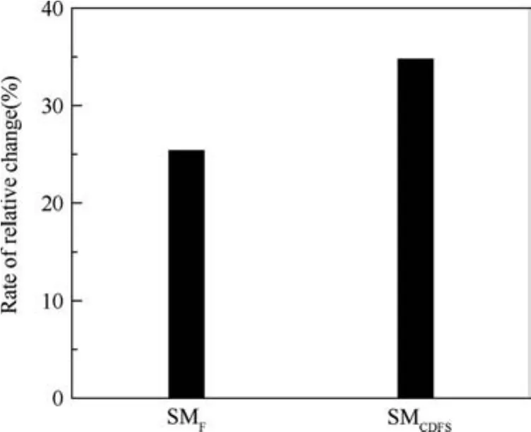
Fig.15 Related surge margins of the ACE versus VANLPT.
3.6.A8on different modes
The original and adjusted values ofA817are shown in Table 8.The histograms of related parameter of the ACE on different working modes are shown in Fig.17.
When the engine operates at Mode M1 and the LP speed is maintained constant,turning downA8increases the HPT inlet total temperature,improves thrust,but decreases the CDFS surge margin.Initially,turning downA8leads to a decrease of the LPT expansion ratio.As a result,the LPT output work decreases leading to a break of the LP work balance.A dropping trend of the LP speed occurs owning to this break.Hence,for a constant LP speed,more fuel should be injected.In this way,the HPT inlet total temperature and the HP speed rise up.The CDFS compression ratio increases due to an increase of the LPT outlet back pressure.Moreover,the CDFS air flow changes a little,while the CDFS working point almost moves up verticality.At the same time,the fan stays relatively stable owning to a nearly constant air flow of the CDFS.As for the HPC,its inlet temperature rises due to the increase of the CDFS compression ratio.Therefore,the HPC referred speed drops.The HPC working point moves down along its working line.
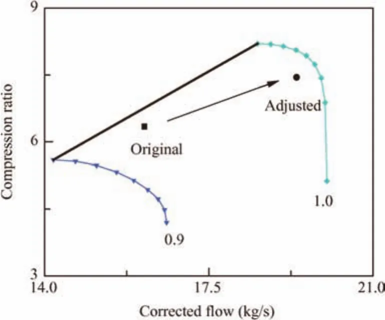
Fig.16 HPC working point versus VANLPT.
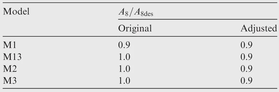
Table 8 The changes of A8at various modes.
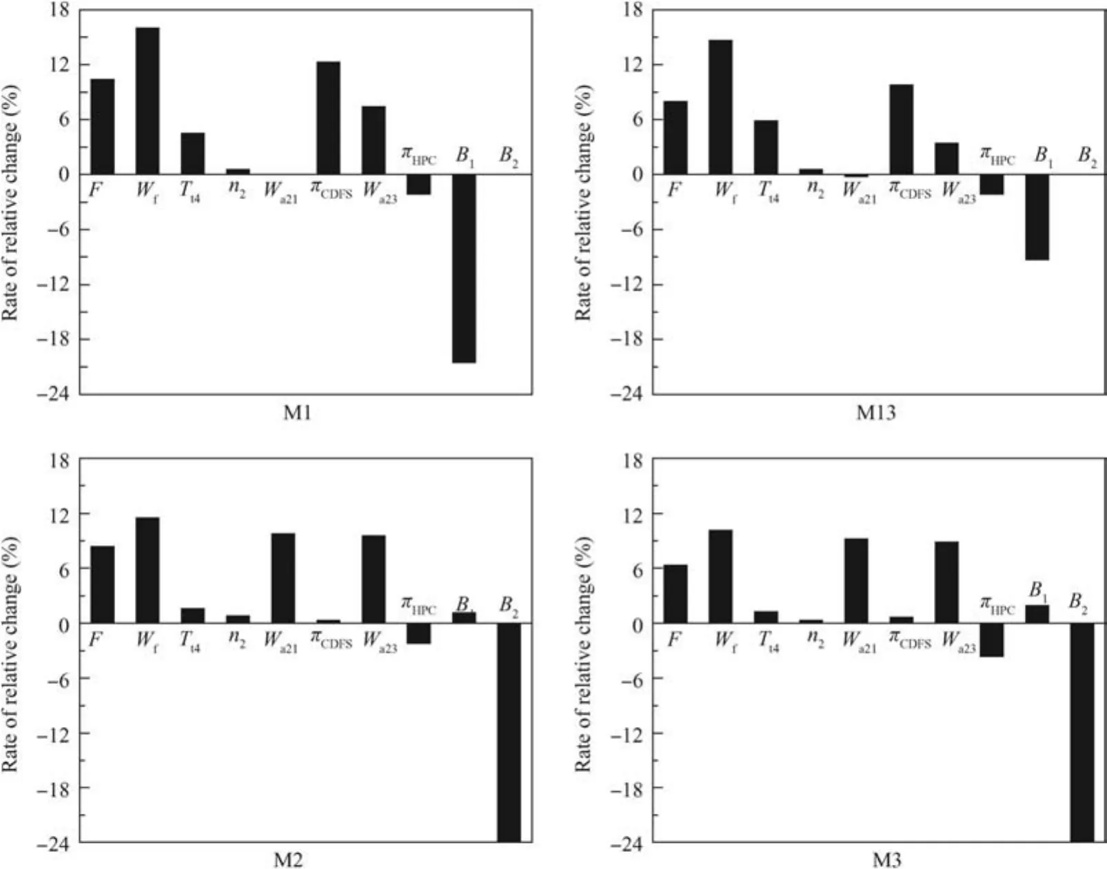
Fig.17 Related parameters of the ACE versus A8.
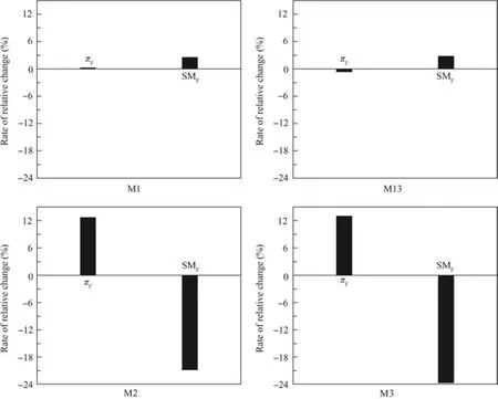
Fig.18 Compress ratio and surge margin of the fan versus A8.
In Fig.18,pFis the fan compression ratio.
At Mode M13,the remaining parameters except the Flade’s flow or compress ratio change similarly compared to those at Mode M1.The Flade working point does not move.In that case,the Flade air flow,pressure ratio,and compression work remain constant.At Mode M2,the fan is affected by turning downA8,which is different from those at Modes M13 and M1.The fan compression ratio increases and the fan surge margin declines seriously,which are shown in Fig.18.At Mode M3,the HPT inlet total temperature is higher and the thrust is larger than those at Mode M2 because of the Flade.
4.Conclusions
An adjustment of variable geometries changes the matching relationship of different components and then affects the engine matching performance of an ACE.This article discusses the influences of six different variable geometries on the performance of an ACE at variable modes and the conclusions are shown below:
(1)When the engine operates at Mode M1 and the LP speed is constant,respectively,turning down VSVHPC,VANLPT,A8,and turning up VSVCDFS,VANHPTcan increase the thrust at the expense of a higher HPT inlet total temperature.However,the influences of these adjustments on the trends of various engine components’working points as well as working lines,the ratio of the rotation speed difference,and the surge margins of compression components are diverse from each other.Therefore,proper adjustments of variable geometries should be done according to the practical requirements of the ACE.
(2)At Mode M13,Both the HPT inlet total temperature and the thrust are higher than those at Mode M1 because of the Flade.The remaining parameters change similarly compared to those at Mode M1.Turning down VSVFladedecreases the HPT inlet total temperature and the thrust,but the CDFS and Fan surge margins decrease a little.Variations of the other geometries do not affect the Flade working point.
(3)At Mode M2,despite of variations of most variable geometries exceptA8,the fan working point almost remains unchanged due to the second bypass air flow split.The remaining parameters change similarly compared to those at Mode M1.However,the fan working point is affected by turning downA8.The fan compression ratio increases and the fan surge margin declines seriously,which is different at Modes M13 and M1.
(4)At Mode M3,Both the HPT inlet total temperature and
the thrust are higher compared to those at Mode M2 also due to the Flade’s operation.The remaining parameters change similarly compared to those at Mode M2.
In a word,the above-mentioned research conclusions provide valuable guidance and advice to the adjustments of the related variable geometries of an ACE at variable modes.
Acknowledgement
This work was supported by the National Natural Science Foundation of China(No.51206005)and Collaborative Innovation Center of Advanced Aero-Engine of China.
1.Kurzke J.The mission defines the cycle:turbojet,turbofan and variable cycle engines for high speed propulsion.NATO;2010.Report No.:RTO Educational Notes,EN-AVT-185 Lecture.
2.Peter V,Walter B.Study of an airbreathing variable cycle engine.Reston:AIAA;2011.Report No.:AIAA-2011-5758.
3.Simmons R.J.Design and control of a variable geometry turbofan with an independently modulated 3rd stream[dissertation].Columbus,Ohio:Ohio State University;2009.
4.GE Co.,Aerodynamic/acoustic performance of YJ101/double bypass VCE with cannular plug nozzle.Washington,D.C.:NASA;1981.Report No.:NASA-CR-159869.
5.Li B,Chen M,Zhu ZL.Steady performance investigation at various modes of an adaptive cycle aero-engine.J Propul Technol2013;34(8):1009–15[Chinese].
6.Zhang X,Liu BJ.Analysis of aerodynamic design characteristics of core driven fan stage.J Aerospace Power2010;25(2):434–42[Chinese].
7.Liu HX.The development of variable cycle engine at GE.China Assoc Sci Technol2013;1–11[Chinese].
8.Chen ZG,Zhang ZS,Liang CY,Qu S.Research on the development of variable cycle engines from conventional turbofan engines.J Shenyang Inst Aeronaut Eng2013;30(3):10–3[Chinese].
9.Li WJ,Niu W.GE adaptive cycle engine test more than expected.Aerodyn Missile J2013;12:44–9[Chinese].
10.Li B,Zhao CW.Consider on variable cycle engine and adaptive cycle engine technology development.Aeronaut Manuf Technol2014(1);54–7[Chinese].
11.Zhu ZL,Zhang J.Performance analysis on variable geometries to turbofan engine.J Aerospace Power1994(4);353–6[Chinese].
12.Chen M,Zhu ZL,Zhu DM,Zhang J,Tang HL.Performance analysis tool for turbine based combined cycle engine concept.J Astro2006;27(5):854–9[Chinese].
13.NATO.Performance prediction and simulation of gas turbine engine operation for aircraft.Marine,Vehicular,and Power Generation,RTO;2007.Report No.:R-AVT-036.
14.Chen M,Tang HL,Zhang H.Turbine based combined cycle propulsion system integration concept design.J Aerospace Eng,Proc Inst Mech Eng,Part G:JAerospace Eng2012;227(7):1068–89.
15.Tang HL,Chen M,Jin DH,Zou ZP.High altitude low Reynolds number effect on the matching performance of a turbofan engine.J Aerospace Eng,Proc Inst Mech Eng,Part G:J Aerospace Eng2013;227(3):455–66.
16.Chen M,Zhu ZL.Goal programming for stable mode transition in tandem turbo-ramjet engines.Chinese J Aeronaut2009;22(5):486–92.
17.Kuo C-W,Veltin J,McLaughlin DK.Acoustic measurements of models of military style supersonic nozzle jets.Chinese J Aeronaut2014;27(1):23–33.
23 January 2016;revised 27 October 2016;accepted 21 November 2016
Available online 14 February 2017
*Corresponding author.
E-mail address:buaa_tang@126.com(H.Tang).
Peer review under responsibility of Editorial Committee of CJA.
猜你喜欢
杂志排行

CHINESE JOURNAL OF AERONAUTICS的其它文章
- Dynamics of air transport networks:A review from a complex systems perspective
- ATM performance measurement in Europe,the US and China
- Network analysis of Chinese air transport delay propagation
- Robustness analysis metrics for worldwide airport network:A comprehensive study
- Evolution of airports from a network perspective–An analytical concept
- Methods for determining unimpeded aircraft taxiing time and evaluating airport taxiing performance