齿轮泵侧隙卸荷的界定标准与验证
2017-11-13孙付春李玉龙文昌明
孙付春,李玉龙,文昌明,钟 飞
齿轮泵侧隙卸荷的界定标准与验证
孙付春,李玉龙,文昌明,钟 飞
(成都大学机械工程学院,成都 610106)
为解决当前泵用齿轮副侧隙大、小界定含糊的问题,基于侧隙传动与困油的性能要求,从双齿啮合区内的2困油容积连通和单齿啮合区卸荷的性能完善方面,通过困油循环及困油过程的分析,建立出2类区域内的困油流量及峰值,推导出卸荷用侧隙、连通用侧隙及其均值和峰值;并进行实例运算和验证分析。结果表明:卸荷区与连通区的困油流量峰值比为3,前者的卸荷负担最大;连通区的真正连通,所需侧隙高达2.41 mm,实际上并不存在;卸荷侧隙大于连通侧隙,以连通侧隙作为侧隙大与小的分界点,卸荷侧隙作为上限值的界定可行;计算与试验的侧隙误差为7.5%,比较吻合,且上限值有20%的安全裕度,比较可靠等。泵用侧隙的界定为大、小侧隙的正确区分提供了参考,也可为后续的相关研究提供参考。
泵;振动;齿轮泵;连通侧隙;卸荷侧隙;大小界定;困油流量
0 引 言
外啮合齿轮泵(简称齿轮泵)是一种用于泵送工作油液的动力泵,有着极其广泛的应用[1]。结构上,一对外啮合齿轮副为其核心部件。该齿轮副在常规的动力传递中,为利于啮合齿廓之间形成润滑油膜、避免因轮齿摩檫发热膨胀而卡死,非工作齿廓之间常留有一定的齿侧间隙,简称侧隙;但侧隙同时也会产生齿间冲击,影响齿轮传动的平稳性。故在满足传动性能要求的基础上,一般采用0.0050.01(为模数,mm)的小侧隙[2],但设计上仍按无侧隙对待。不过作为常规齿轮传动在泵中的特殊应用,虽然大侧隙能有效改善困油性能,却同时也造成了容积效率下降、振动加剧、噪声增加[3-5];反之,容积效率提高和振动减缓、噪声下降[6-8],同时也降低了困油性能[9-12],所以泵用侧隙同样会受到一定的限制,一般采用0.010.08的有侧隙[13],或参照推荐值选择[14]。
目前,在关于容积效率和困油性能等的文献研究中,一般都需要计算通过侧隙处的介质交换流量,但针对某一具体的侧隙值,文献[13]虽然给出了有侧隙或者无侧隙的界定标准,但侧隙究竟属于小侧隙还是大侧隙,一直很模糊。更多的是以小侧隙的名义默认双齿啮合区内2困油容积的非连通问题[15-17];或以大侧隙的名义默认双齿啮合区内2困油容积的连通、单齿啮合区域的无困油问题等[5,13,18]。而偏偏大、小侧隙的界定又直接涉及到后续不同的计算方法[13,19-20],例如,卸荷槽形位计算的不同方法[13,21-24]等,这些恰恰被大多数的研究所忽略。即针对泵用的这对齿轮副,何为侧隙的大、小,截至目前为止,学术界并没有给出具体的划分界定标准。为此,论文拟从双齿啮合内2个困油容积的连通和单齿啮合区内困油性能的完善角度,对此进行深入的研究,并给出相应的界定标准。
1 有无侧隙的现有界定
何谓有、无侧隙,文献[13]给出了如式(1)的界定式。设为公法线方向上的侧隙值,mm;0为有、无侧隙的分界值,mm。当<0时,由于工作介质通过侧隙的阻力相当大,介质的通过流量被认为是微乎其微接近于零,泵几何尺寸上的计算,可按无侧隙关系式来确定;否则,按有侧隙关系式来确定。而有侧隙又可分为大侧隙和小侧隙,但目前对此却没有明显的界定,大小之分比较含糊与笼统。
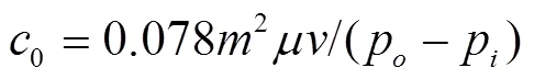
式中为介质动力黏度,(N·s)/m2;为节圆圆周速度,m/s;p与p为泵的高、低压腔的介质压力,Pa;为模数,mm。
2 困油循环及困油过程
图1描述了齿轮泵的困油循环及困油过程。轮心分别记为1、2,偏向1、2侧的2个困油容积、困油压力,分别记为1、2,mm3和1、2,Pa。其中,图1中a→b→c→d→e和d→e→f→a→b分别为1、2的困油循环;a→b→c→d→e→f→a为一个完整的困油过程。其中,a为1刚刚形成;b为2刚刚脱开;c为1在最小困油容积时的位置;d为2刚刚形成;e为1刚刚脱开;f为2在最小困油容积时的位置。a→b为单侧隙双齿啮合区间,简称为侧隙连通区;b→c→d和e→f→a为单侧隙单齿啮合区间,简称为侧隙卸荷区。设刚形成1的啮合点在1工作齿面上对应的曲率半径为,并以此作为困油过程的位置变量,记对应于图1中a~f的6个位置的分别用s~表示[1],mm。其中
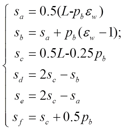
式中为理论啮合线的长度,mm;p为基节,mm;ε为根切重合度[25]。由于泵用齿轮副允许存在一定的根切现象,2上的齿顶点能否参与啮合,取决于根切程度[26];它们均为齿形参数的函数。
注:1、2表示主、从齿轮的轮心;表示啮合位置;表示侧隙位置;p表示进口压力,Pa;p表示出口压力,Pa;1、2表示偏向1、2侧的困油容积,mm3;1、2表示1、2的困油压力,Pa;为由主动轮上啮合点处的曲率半径所定义的位置变量,mm;s表示1刚刚形成位置,mm;s表示2刚刚脱开位置,mm;s表示1的最小容积位置,mm;s表示2刚刚形成位置,mm;s表示1刚刚脱开位置,mm;s表示2的最小容积位置,mm;下同。
Note:1and2indicate two center points of driving gear and driven gear;indicates meshing point;indicates backlash point;pindicates inlet pressure, Pa;pindicates outlet pressure, Pa;1and2indicate the two different trapped-oil volumes on1side and2side, mm3;1and2indicate trapped-oil pressure of1and2, Pa;indicates the location variables defined as the curvature radius of meshing point of driving gear, mm;sindicates the location of1just formed, mm;sindicates the location of2just disappeared, mm;sindicates the location of1with minimum volume, mm;sindicates the location of2just formed, mm;sindicates the location of1just disappeared, mm;sindicates the location of2with minimum volume, mm; similarly hereinafter.
图1 困油循环及困油过程
Fig.1 Trapped oil circulation and trapped oil process
3 困油流量及峰值
3.1 侧隙卸荷区
在侧隙卸荷区内,始终只存在由一个啮合点和一个侧隙点所围成的单一困油容积1或2。每单一的困油容积及其变化率为
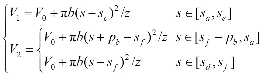
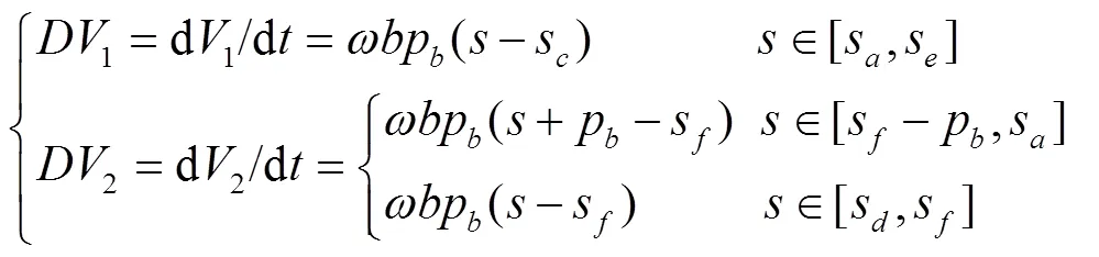
式中0为最小的困油容积,mm3;为齿数,称1、2为1、2对时间的变化率,称为困油流量,mm3/s,它们的峰值均为

式中Q为侧隙卸荷区内的困油流量峰值,mm3/s;为齿宽,mm;为角速度,rad/s。
3.2 侧隙连通区
小侧隙时,在图1中[s,s]区间内的1、2不能连成一体,并形成了2个单一的困油容积。此时,每个单一1或2均由一个啮合点和一个侧隙点所围成。其间的困油流量与式(4)相同,峰值与式(5)相同。
大侧隙时,1、2连成一体,该连体困油的体积、压力设为和,且该连体与高、低压油腔之间,分别被2个啮合点所隔开。由于该2个啮合点处的啮合间隙极小,此时虽为大侧隙,但困油现象仍始终存在。此时
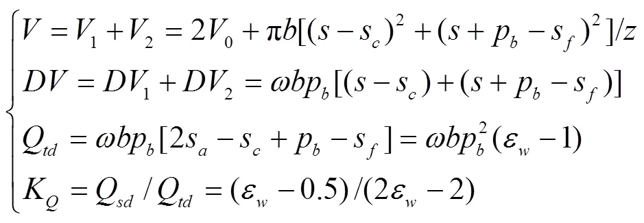
式中为1、2的连体体积,mm3;为对应于的困油流量,mm3/s;Q为侧隙连通的困油流量峰值,mm3/s;Q为侧隙卸荷的困油流量峰值,mm3/s;K为卸荷区和连通区困油流量的峰值比。
例取ε=1.1,则K=3,说明侧隙卸荷区比连通区内的困油压力卸荷的负担大很多。
4 侧隙界定的理论计算
如果设困油流量以困油容积的膨胀为正,压缩为负;困油压力的变化率以压力增大为正,降低为负;且仅考虑困油流量是产生困油压力的唯一主因。那么,困油的体积弹性模量可定义为[1]
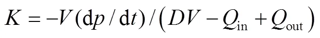
式中为体积弹性模量,Pa,in、Qout为外界流进、流出困油容积的交换流量,mm3/ s;且记以流入为正。则

式中为对时间的变化率,Pa/s。
在侧隙连通区内,对于2个单一的1、2,各自与外界交换的总流量,包括通过侧隙的流量(简称为侧隙流量)、轴向(间隙)流量、啮合(间隙)流量、卸荷槽的卸荷流量等,如将除侧隙流量外的其他流量均以侧隙流量的形式体现,则所折算出的连通侧隙,如图2所示,故该区间内的困油为一封闭容积。由2>1,得
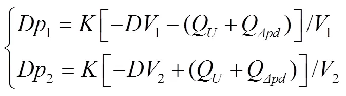
式中1、2为1、2对时间的变化率,Pa/s;Q、QΔpd为侧隙处的剪切流量和压差流量,mm3/s。
注:Q、Δpd表示侧隙处的剪切流量和压差流量,mm3·s-1;c表示连通侧隙,mm;1、2和表示压力变化率,Pa·s-1;1、2、表示容积变化率,mm3·s-1;下同。
Note:QandΔpdindicate shear flow and differential pressure flow through backlash gap, mm3·s-1; cindicates backlash for connection of two trapped-oil volumes, mm;1,2andindicate trapped-oil pressure rate of change over time, Pa·s-1;1and2,indicate trapped-oil volume rate of change over time, Pa·s-1; similarly here in after.
图2 连通侧隙的计算
Fig.2 Gap calculation of backlash for connection
在侧隙连通区内的任何位置,由于困油流量与流进、流出困油容积的各流量,始终处于平衡状态,即Δp=p1−2≈1−p始终为一确定值。则2≡1≡0。
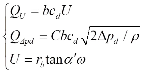
式中Δp为许可压差,Pa,为节圆压力角,rad,c为满足Δp的侧隙值,mm;为流量系数;为等效卷吸速度,mm/ s;为介质密度,kg/m3。得
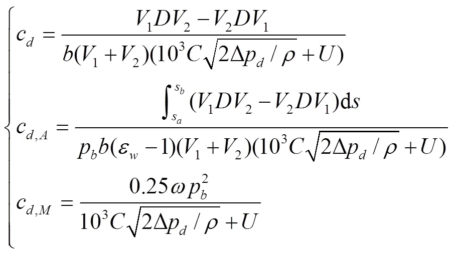
式中c,A和c,M为c均值和最大值,mm。其中,最大值的位置为=0.5(s+s)。
图2中2个单一的1、2如能实现真正的连通,即需满足Δp≡0,则真正连通下的侧隙为

式中c为实现零压差所需要的最小侧隙,mm,为分度圆压力角,rad。
例取=3 mm,=10,=20°,=30°,则c=2.41 mm,该值很大,小齿数的泵用齿轮副是无法实现的,即2个单一的1、2的真正连通是不存在的,只能是一定允许压差下的近似连通。
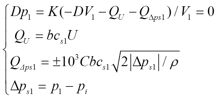
在侧隙卸荷区内,对于单一的1或2,各自与外界交换的总流量,同样也包括通过侧隙的侧隙卸荷流量、轴向流量、啮合流量、卸荷槽的卸荷流量等,如将除侧隙卸荷流量外的其他流量均以侧隙卸荷流量的形式体现,则可折算出相应的卸荷侧隙。对于1,由[27]
得
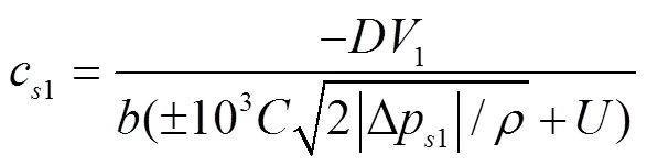
式中Δp1为许可压差,Pa,1为满足Δp1时1所需的折算侧隙的下限值,mm,当1>p,取“+”;否则,取“-”。
对于2,由
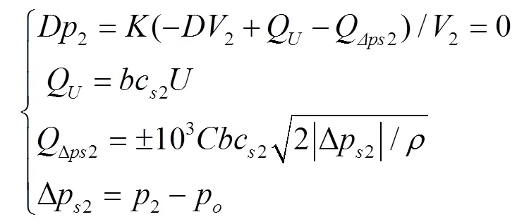
得
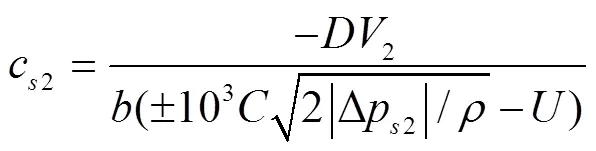
式中Δp2为许可压差,Pa,2为满足Δp2时2所需的折算侧隙的下限值,mm,当2>p,取“+”;否则,取“-”。
取
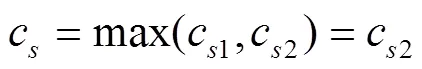
式中c为c1和c2中的最大值,mm。且
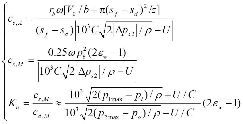
式中c和c为c的均值和最大峰值,mm;K为c与c的比值,1max、2max为困油压力1、2的最大峰值,Pa。
由于1max≈2max,所以K大于1,即c>c。定义
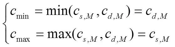
式中max与min为侧隙的上、下限。
由此定义出侧隙的大与小,
5 实例运算及验证
文献[17]提供了试验用侧隙=30、50、200m的一组试验结果,如图3a所示。试验用泵的几何参数为模数4.75齿数10,齿顶圆直径58 mm,中心距48.8 mm,=12.7 mm,由齿轮副三维模型测得0=20 mm3,对应于试验用侧隙分别为30、50、200m的压力角为23°50′、23°40′、23°10′,出口压力p为2、1、2 MPa。=870 kg/m3,=0.09 Pa·s,=0.62。由图3a中,知转速=1 000 r/min下困油压力的峰值为2.7、3.7、7.3 MPa。另外,由矩形卸荷槽距中心线的距离B=6.4 mm,经计算知采用的是大侧隙卸荷槽,其卸荷效果一般[13]。
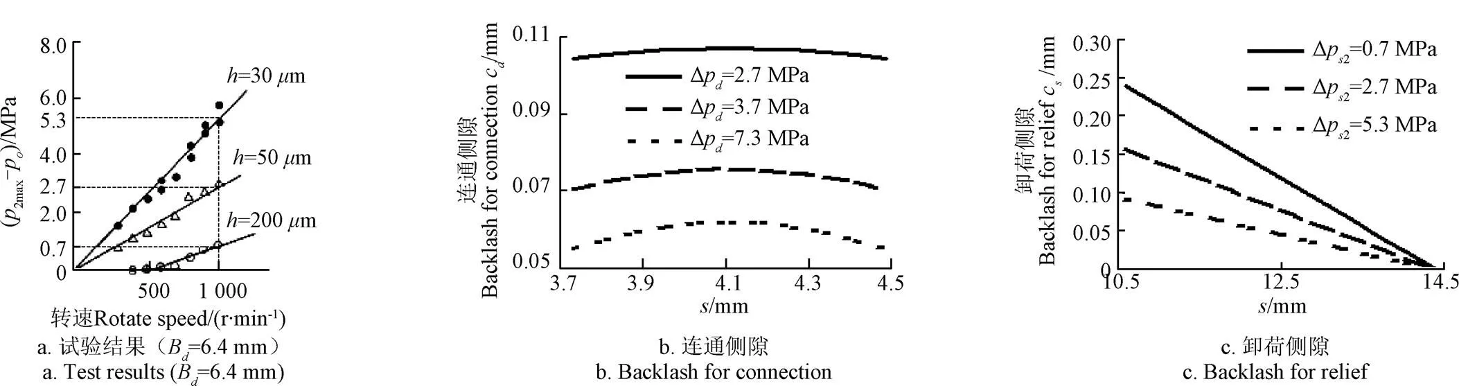
注:Δpd为连通许可压差,Pa;Δps2为卸荷许可压差,Pa;p2max为p2的最大值,Pa;Bd表示卸荷槽离中心线的距离,h表示试验用侧隙,下同。
经计算得传动性能所要求的0.0050.01的侧隙为23.75~47.5m;困油性能所要求的0.01~0.08的侧隙为47.5~380m;0=3~7m。由此可见,泵用齿轮副均为有侧隙齿轮副。
分别将Δp取2.7、3.7、7.3 MPa和Δp2取0.7、2.7、5.3 MPa,分别代入式(11)和式(18),计算结果,如图4所示。其中,图3a为试验结果,图3b为择算后的连通侧隙,图3c为择算后的卸荷侧隙,其最大值和均值,如表1所示。其中,d,和s,为由卸荷槽关闭点位置,即B=6.4 mm计算出的连通侧隙和卸荷侧隙。
困油压力峰值多出现在卸荷槽关闭点附近[28-29],动态的流场分析也说明了这一点[30],即此时的卸荷槽的卸荷流量近乎为零,啮合流量本来就很小,也近乎忽略。因此,在卸荷槽关闭点附近,除侧隙外的其他交换流量近乎为轴向流量。
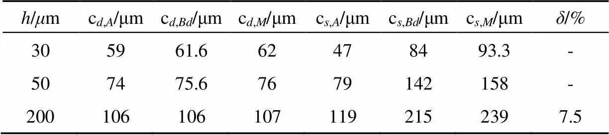
表1 六类侧隙值的计算结果
注:d,、d,表示连通侧隙的均值和最大峰值;s,、s,表示卸荷侧隙的均值和最大峰值;d,表示卸荷槽关闭点附近的连通侧隙值;s,表示卸荷槽关闭点附近的卸荷侧隙值;为大侧隙时理论值与试验值的相对误差,%。
Note:d,andd,indicate the mean value and the maximum peak value of backlash gap used for the connection of two trapped-oil volumes;s,ands,indicate the mean value and the maximum peak value of backlash gap used for trapped-oil relief;d,indicates the backlash gap used for the connection of two trapped-oil volumes when the trapped-oil relief was closed;s,indicates the backlash gap used for trapped-oil relief when the trapped-oil relief was closed;indicates the relative error between theoretical value and experimental value when large backlash,%.
表1中=200m下的择算侧隙值s,=215m,即其中的s,−15m为以轴向流量为主的其他流量的择算量,其他流量忽略后的误差为(s,−)/=7.5%。且max=239m≥=200m,说明有(max−)/≈20%的安全裕度,比较可靠。
图3a中=30、50m本为小侧隙,在所计算出的max中超过60%的部分,用于弥补其他流量,此时也就不存在所谓的连通问题。由于齿轮泵侧隙常大于85m[14],=30、50m在实际运用中,并不常见。
在=30、50m的情况下,如采用min=62、76m作为实际的侧隙值,则由式(15)的计算,原有的Δp为7.3、3.7 MPa,减小后为1.7、1.6 MPa,此时2个单一的1、2可视为近乎的连通。说明以min作为侧隙大与小的界定参考,是可行的。
6 结 论
1)侧隙卸荷区和侧隙连通区的困油流量比为3,侧隙卸荷区内的卸荷负担最大。侧隙连通区的真正连通,所需侧隙高达2.41 mm,实际上并不存在。
2)卸荷用侧隙大于连通用侧隙,以107m的连通侧隙作为侧隙大与小的分界点,以239m的卸荷侧隙作为侧隙上限的界定可行。计算侧隙与试验侧隙的误差为7.5%,且约有20%的安全裕度,理论计算和试验结果比较吻合。
[1] 李玉龙. 外啮合齿轮泵困油机理、模型及试验研究[D]. 合肥:合肥工业大学,2009.
Li Yulong. Mechanism, Modeling and Experiment Investigation of Trapped Oil in External Gear Pump[D]. Hefei: Hefei University of Technology, 2009. (in Chinese with English abstract)
[2] 闻邦椿. 机械设计手册[M]. 第5版. 北京:机械工业出版社,2010.
[3] Yanada H, Ichikawa T, Itsuji Y. Study of the trapping of fluid in a gear pump[J]. Proceedings of the Institution of Mechanical Engineers Part A Journal of Power & Energy, 1987, 201(11):39-45.
[4] Eaton M, Keogh P S, Edge K A. The modelling, prediction, and experimental evaluation of gear pump meshing pressures with particular reference to aero-engine fuel pumps[J]. Proceedings of the Institution of Mechanical Engineers Part I Journal of Systems & Control Engineering, 2006, 220(5): 365-379.
[5] 李玉龙,刘春艳,王生. 大侧隙外啮合齿轮泵的困油特性和流量特性[J]. 机械科学与技术,2015,34(3):454-458.
Li Yulong, Liu Chunyan, Wang Sheng. The trapped oil characteristics and flow characteristics with large backlash gap in external gear pumps[J]. Mechanical Science and Technology for Aerospace Engineering, 2015, 34(3): 454-458. (in Chinese with English abstract)
[6] Dalpiaz G, Fernández del Rincón A, Mucchi E. Modeling meshing phenomena in gear pumps[C]//Proceedings of ISMA 2004, Leuven, Belgium, September 2004: 949-963.
[7] Eaton M, Keogh P S, Edge K A. Modeling and simulation of pressures within the meshing teeth of gear pumps[C]// Proceedings of International Conference on Recent Advances in Aerospace Actuation Systems and Components, Toulouse, France, 2001.
[8] Borghi M, Milani M, Paltrinieri F, et al. The Influence of Cavitation and Aeration on Gear Pumps and Motors Meshing Volumes Pressures[C]// ASME 2006 International Mechanical Engineering Congress and Exposition, 2006:47-56.
[9] 李玉龙,孙付春. 齿轮泵齿侧间隙与卸荷槽间距关系的定量分析[J]. 农业工程学报,2012,28(22):63-68.
Li Yulong, Sun Fuchun. Quantitative analysis of relationship between backlash value and distance of two relief grooves in external gear pump [J]. Transactions of the Chinese Society of Agricultural Engineering (Transactions of the CSAE), 2012, 28(22): 63-68. (in Chinese with English abstract)
[10] 李玉龙,孙付春. 齿轮泵困油的分析模型及侧隙计算[J]. 排灌机械工程学报,2011,29(2):118-122.
Li Yulong, Sun Fuchun. Analysis model on trapped oil and backlash calculation in external gear pump[J]. Journal of Drainage and Irrigation Machinery Engineering, 2011, 29(2): 118-122. (in Chinese with English abstract)
[11] 李玉龙. 外啮合齿轮泵侧隙流量的精确计算[J]. 排灌机械工程学报,2013,31(8):656-661.
Li Yulong. Accurate calculation of backlash flow in external gear pump[J]. Journal of Drainage and Irrigation Machinery Engineering, 2013, 31(8): 656-661. (in Chinese with English abstract)
[12] 李玉龙,唐茂. 困油压力对齿轮泵流量脉动的影响分析[J]. 农业工程学报,2013,29(20):60-66.
Li Yulong, Tang Mao. Influence analysis of trapped oil pressure on flow pulsation in external gear pumps[J]. Transactions of the Chinese Society of Agricultural Engineering (Transactions of the CSAE), 2013, 29(20): 60-66. (in Chinese with English abstract)
[13] 何存兴. 液压元件[M]. 北京:机械工业出版社,1985.
[14] 河北远东泵业有限公司.怎样检查齿轮泵齿轮啮合状况[EB/OL].[2009-10-30].http://www.Chilunbeng.org/Information/ Info-show. asp.
[15] 何培双.无侧隙啮合齿轮泵[J]. 液压与气动,2004(7): 62-63.
He Peishuang. Gear pump of meshing engagement without backlash[J]. Chinese Hydraulics & Pneumatics, 2004(7): 62-63. (in Chinese with English abstract)
[16] 甘学辉,侯东海,吴晓铃. 斜齿齿轮泵无侧隙啮合困油特性的研究[J]. 机械工程学报,2003,39(2):145-148.
Gan Xuehui, Hou Donghai, Wu Xiaoling. Research on trapping property of no clearance helical gear pump[J]. Chinese Journal of Mechanical Engineering, 2003, 39(2): 145-148. (in Chinese with English abstract)
[17] Yanada H, Ichikawa T, Itsuji Y. 齿轮泵困油现象研究[J]. 液压与气动,1988(3):47-52.
Yanada H, Ichikawa T, Itsuji Y. The phenomenon of trapped-oil in gear pump[J]. Chinese Hydraulics & Pneumatics, 1988(3): 47-52. (in Chinese with English abstract)
[18] 甘学辉,吴晓铃,向平. 斜齿齿轮泵有侧隙啮合困油特性的研究[J]. 机械传动,2002,26(2):8-10.
Gan Xuehui, Wu Xiaoling, Xiang Ping. Research on trapping property helical gear pump with clearance[J]. Journal of Mechanical Transmission, 2002, 26(2): 8-10. (in Chinese with English abstract)
[19] 李玉龙,刘焜. 外啮合齿轮泵困油面积和卸荷面积计算式的建立[J]. 农业机械学报,2009,40(6):203-207.
Li Yulong, Liu Kun. Established formulas for trapped-oil area and relief-load area of external spur-gear pump[J]. Transactions of the Chinese Society of Agricultural Machinery, 2009, 40(6): 203-207. (in Chinese with English abstract)
[20] 李玉龙,刘焜. 外啮合齿轮泵卸荷面积的精确仿真分析[J].农业工程学报,2009,25(3):42-45.
Li Yulong, Liu Kun. Precise simulation analysis of relief area of external spur-gear pump[J]. Transactions of the Chinese Society of Agricultural Engineering (Transactions of the CSAE), 2009, 25(3): 42-45. (in Chinese with English abstract)
[21] 王建,吴炳胜,马戎,等. 齿轮泵卸荷槽设计的新方法[J]. 机械传动,2013,37(12):73-76.
Wang Jian, Wu Bingsheng, Ma Rong, et al. New method of gear pump unloading groove design[J]. Journal of Mechanical Transmission, 2013, 37(12): 73-76. (in Chinese with English abstract)
[22] 臧克江,周欣,顾立志,等. 降低齿轮泵困油压力新方法的研究[J]. 中国机械工程,2004,15(7):579-582. Zang Kejiang, Zhou Xin, Gu Lizhi, et al. Study on new method of reducing the trap pressure of gear pump[J]. China Mechanical Engineering, 2004, 15(7): 579-582. (in Chinese with English abstract)
[23] 李玉龙. 齿轮泵圆形卸荷槽下的困油压力分析[J]. 中国农业大学学报,2014,19(4):155-160.
Li Yulong. Trapped-oil pressure analysis of gear pump with arc unloading groove[J]. Journal of China Agricultural University, 2014, 19(4): 155-160. (in Chinese with English abstract)
[24] 李玉龙,孙付春,唐茂. 高速齿轮泵渐开线型卸荷槽的设计与分析[J]. 机械科学与技术,2014,33(9):1377-1381.
Li Yulong, Sun Fuchun, Tang Mao. Design and analysis of the relief groove with involutes shape in the higher speed external gear pumps[J]. Mechanical Science and Technology for Aerospace Engineering, 2014, 33(9): 1377-1381. (in Chinese with English abstract)
[25] 李玉龙,袁影,吴柏强,等. 泵用齿轮副根切重合度的公式创建[J]. 机床与液压,2017,45(1):84-88.
Li Yulong, Yuan Ying, Wu Boqiang, et al. A new contact ratio formula created for gear pairs with undercut in external gear pumps[J]. Machine Tool & Hydraulics, 2017, 45(1): 84-88. (in Chinese with English abstract)
[26] 李玉龙,孙付春,姚旗,等. 航天器用超低黏度齿轮泵轻量化设计[J]. 农业工程学报,2016,32(21):109-114.
Li Yulong, Sun Fuchun, Yao Qi, et al. Lightweight design of gear pumps with ultra low viscosity medium used in spacecraft[J]. Transactions of the Chinese Society of Agricultural Engineering (Transactions of the CSAE), 2016, 32(21): 109-114. (in Chinese with English abstract)
[27] 李玉龙. 齿轮泵最大困油压力解析式的建立与验证[J]. 农业工程学报,2013,29(11):71-77.
Li Yulong. Establishment and verification of analytic formula for maximum trapped-oil pressure in external gear pump[J]. Transactions of the Chinese Society of Agricultural Engineering (Transactions of the CSAE), 2013, 29(11): 71-77. (in Chinese with English abstract).
[28] 李玉龙. 外啮合齿轮泵困油膨胀区的最小压力[J]. 排灌机械工程学报,2013,31(12):1049-1055.
Li Yulong. The minimal trapped-oil pressure of expansion stage in external gear pump[J]. Journal of Drainage and Irrigation Machinery Engineering, 2013, 31(12): 1049-1055. (in Chinese with English abstract)
[29] 李玉龙,刘焜. 外啮合齿轮泵动态困油模型及其参数影响分析[J]. 农业机械学报,2009,40(9):214-219.
Li Yulong, Liu Ku. Dynamic model of trapped oil and effect of related variables on trapped oil pressure in external spur-gear pump[J]. Transactions of the Chinese Society for Agricultural Machinery, 2009, 40(9): 214-219. (in Chinese with English abstract)
[30] 陈康,许同乐,王营博. 基于振动与流场耦合齿轮泵困油现象分析[J]. 机床与液压,2016,44(19):133-137.
Chen Kang, Xu Tongle, Wang Yingbo. Analysis of gear pump oil trapping phenomenon based on vibration and flow field coupling[J]. Machine Tool & Hydraulics, 2016, 44(19): 133-137. (in Chinese with English abstract)
Demarcated standard and verification of backlash relief in external gear pumps
Sun Fuchun, Li Yulong, Wen Changming, Zhong Fei
(,,610106,)
The gear pumps are used for pumping the working fluid, and its key component is a pair of gear pairs. In the power transmission, the backlash of the gear pair is used to form the lubricating oil film to avoid sticking due to the friction and heat expansion of the gear teeth, but it also affects the stability of the oil film. The choice of backlash in the gear pump is also limited. The backlash of the gear has an influence on the trapped oil performance and volumetric efficiency of the gear pump, while the definition whether there is a backlash existed and the definition what is large backlash and what is small backlash is vague. Based on the common requirements of different backlash values to transmission performance and trapped oil performance, the special trapped-oil circulation and trapped-oil process were analyzed in this study, and the emphasis was on the double teeth meshing range and the single tooth meshing range. From the connection aspect of two different trapped-oil volumes in double teeth meshed range and the improvement aspect of trapped oil performance in single tooth meshed range, we used to separately calculate dynamic trapped-oil flow rate and its maximum value under the two different ranges of double teeth meshing and single tooth meshing, as well as the different formulas to separately calculate dynamic backlash values, its mean value, its lower limiting value used for the connection in double teeth meshed range, and the relief in single tooth meshed range. From such exercises, we derived the definition what was large backlash and what was small backlash. The backlash therefore was defined as, a small backlash was when the backlash value was less than the maximum peak of the backlash for connection, and when the backlash value was greater than the maximum peak of the backlash for connection and less than the maximum peak of the backlash for trapped oil relief, it was a large backlash, and when the backlash value was greater than the maximum peak of the backlash for trapped oil relief, it belonged to the large backlash. An instance of an external gear pump which backlash was 30, 50, 200m, was operated and its operation results were analyzed by the theory we developed. The results showed that when the trapped oil flow peak ratio of the unloading area and the connected area was 3, the unloading burden of the former was large. In fact, the really communicating to the communication area required up 2.41 mm backlash, which did not actually exist. So the gear pairs used in gear pumps was the gear pairs with backlash forever. The absolute connection of each other of two different trapped-oil volumes in double teeth meshed range and the absolute trapped-oil relief in single tooth meshed range were nonexistent, but only relatively existed under a certain permission pressure difference. As long as the trapped-oil relief requirement in single tooth meshed range was satisfied by an adopted backlash value, then the connection of two different trapped-oil volumes each other would naturally be met by the adopted backlash value. Backlash for trapped oil relief was larger than the backlash for connection, which can be used in definition what was large backlash and what was small backlash, and the backlash for trapped oil relief can be used as the upper limit. The error in the calculation and experiment was 7.5%, which was reasonable, and the upper limit of the safety margin was 20%, which was reliable. This research provided a reference for distinguishing large backlash between small backlash by Pump backlash defining, and which also provided a theoretical basis for the subsequent studies.
pumps; vibrations; gear pumps; backlash for connection; backlash for relief; demarcated size; trapped-oil flow rate
10.11975/j.issn.1002-6819.2017.20.008
TH325; TH137.3
A
1002-6819(2017)-20-0061-06
2017-04-18
2017-09-01
四川省自然科学重点资助项目(16ZA0382);北京卫星制造厂资助项目(20804)。
孙付春,博士,副教授,主要从事农业机械方面的基础研究与应用开发。Email:fch.sun@163.com
孙付春,李玉龙,文昌明,钟 飞. 齿轮泵侧隙卸荷的界定标准与验证[J]. 农业工程学报,2017,33(20):61-66. doi:10.11975/j.issn.1002-6819.2017.20.008 http://www.tcsae.org
Sun Fuchun, Li Yulong, Wen Changming, Zhong Fei. Demarcated standard and verification of backlash relief in external gear pumps[J]. Transactions of the Chinese Society of Agricultural Engineering (Transactions of the CSAE), 2017, 33(20): 61-66. (in Chinese with English abstract) doi:10.11975/j.issn.1002-6819.2017.20.008 http://www.tcsae.org