地下储气库井管柱沿程流体状态数值模拟
2017-09-18刘铭刚王建军闫怡飞谢巍杨秀娟闫相祯张艳茹
刘铭刚王建军闫怡飞谢巍杨秀娟闫相祯张艳茹
1.中国石油大学(华东);2.中国石油集团石油管工程技术研究院;3.中国石油华北油田分公司
地下储气库井管柱沿程流体状态数值模拟
刘铭刚1王建军2闫怡飞1谢巍3杨秀娟1闫相祯1张艳茹3
1.中国石油大学(华东);2.中国石油集团石油管工程技术研究院;3.中国石油华北油田分公司
确定注采过程中天然气在油管柱内的运动状态是分析储气库井管柱受力、确定冲蚀位置的关键。根据井身结构和运行参数建立天然气流经储气库定向井油管柱过程的物理模型,通过数值试验研究造斜段管柱内沿程速度、涡量和近壁压力分布;分析注采压差、井斜角及油管内径对管柱近壁压力的影响规律。结果表明:油管柱内流体状态受注采压差和井身结构影响,天然气流速和近壁压力在流入流出造斜段时发生波动;管柱沿程速度和动压随井深增大而减小,冲蚀点位置出现在造斜段流入端和流出端管柱中心线与最大狗腿角位置径向线的连线上;随着注采压差增大,流入端和流出端弯曲外侧和内侧平均压程比均明显增大;随着井斜角增大,流入端弯曲外侧和内侧的平均压程比增大,流出端弯曲外侧和内侧的平均压程比减小;随着油管内径增大,流入端弯曲外侧和内侧的平均压程比减小,流出端弯曲外侧和内侧的平均压程比增大。
地下储气库; 定向井; 造斜段; 冲蚀; 计算流体力学
目前国内地下储气库类型以衰竭油气藏型为主,其中定向储气库井所占比例很大。生产管柱作为油气生产中的关键工具,面对储气库循环注采的复杂工况,其功能、结构完整性对储气库作业效率甚至安全都有直接影响。其中封隔器管柱作为储气库“又采又注”作业方式的控制枢纽,其在注采过程中承受高速气流的作用,其质量对全井管柱的寿命和安全产生影响。由于流体在管路内的运动状态和压力变化主要受管路结构及截面特性影响[1-3],因此研究地下储气库注采过程中油管柱内流体状态和气体冲蚀位置,研究不同工况参数下的速度、压力分布规律,对储气库井设计、施工和管柱选材具有重要意义。
国内外学者在弯曲管流的理论、试验及计算方面做了许多工作:Jeffery L(1988)[4]等推导了理想气体音速流动时运动状态方程并与低速流进行了比较;Elling Sletfjerding(2003)[5]设计了气体在粗糙管路中的流动状态对比试验,给出了管路沿程近壁压力分布基本规律;Mazumder(2008a,2008b)和Deng(2005)[6-8]提出并改进了确定弯曲管路冲蚀位置的试验方法;Stack and Abdurrahman(2011)、Zhang(2012)、Tan(2012)、Li(2010)、Suzuki(2008)和 Zeng(2014)[3,9-13]利用计算流体力学仿真(CFD)技术就弯曲管路流体冲蚀问题开展了一系列递进的工作,提出高速管流的常用计算模型和参数取值依据;Ferng Y M(2008,2010)[14-15]和 Zhu(2012,2014a,2014b)[16-18]利用 CFD 技术对输气薄壁管道及气体钻井中的冲蚀问题进行了研究,国内的练章华等(2012)和王嘉淮等(2015)[19-20]对高压气井和地下储气库井管柱的气体冲蚀问题进行了初步研究。本文将上述研究作如下补充:根据井身结构和运行参数建立天然气流经定向储气库井油管柱的流体力学模型,通过数值试验研究一定工况下定向井造斜段管柱内沿程速度和近壁压力分布,并对比不同日注采量、井斜角和油管内径对管柱近壁压力的影响规律。
1 模型建立
Modeling
1.1 数学模型
Mathematical model
地下储气库井处于注入工况时天然气经压缩机压缩后注入井底,处于采出工况时天然气自井底流向井口,可假设油管柱内运动流体为单相可压缩流体。在ANSYS CFX/CFD模块中选择Renormalizationgroup(RNG) k-ε涡黏湍流模型进行数值计算,该模型的连续方程和运动方程分别为

式中,xi,j,k对应空间坐标系中的i、j、k方向的距离,m;Ui,j,k表示流体在 i、j、k 方向上的瞬时速度分量,m/s;SM为体积力,N;ρ为相对密度,kg/m3;μeff为有效动力黏度,数值上等于分子(动力) 黏度μ与湍流黏度 μt的和,μPa·s;p 为静压,MPa;对实际可压缩流体作如下修正
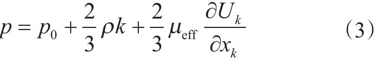
式中,p0为流体不可压缩时的静压,本文中对应计算工况中的入口压力,MPa。

式中,Kronecker积分项 δij在 i=j时,ρuiuj为正应力,为切应力,MPa。
湍动能k和湍动能耗散率ε分别由式(5)、(6)描述的传递方程得到,至此方程(1)、(2)封闭。
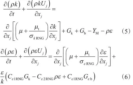
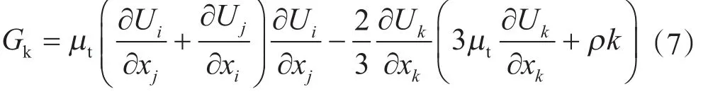
式中,i和j表示坐标方向;k表示单位质量气体的湍动能,J;ε表示相对湍动能耗散率;σkRNG为k方程湍流模型常数,取0.7179;σεRNG为ε方程湍流模型常数,取 0.7179;Cε1RNG、Cε2RNG是湍流模型常数,分别取1.42、1.68;Gk是跟平均速度梯度有关的湍动能生成项;Gb和Gεb是与浮力有关的湍动能生成项;Gk为黏度引起的涡量项,由下式求得
YM是流体可压缩性引起的相对湍动能耗散率改变量,由下式求得


1.2 物理模型
Physical model
为保证数值计算结果与实际工况具有可比性,以某地下储气库试验井井身结构为物理模型基础,根据实际井身数据,建立直井段、造斜段和带封隔器管柱段数值模型。模型以入口端面为源面,采用六面体网格进行单元划分,弯曲管柱段采用楔形网格过渡和加密。
在ANSYS CFX/CFD流体分析模块中设置管柱流入、流出端为压力边界,以注气工况为例进行分析,计算时压缩机出口(流入端)压力恒定,初始井底(流出端)压力为20 MPa,参考环境温度为56.25 ℃,按充分发展的湍流进行初始化设置。假定油管壁面无滑移,计算模型和湍流模型常数按1.1节描述的Renormalization-group(RNG)k-ε涡黏湍流模型设置,选择Segregated Solver算法求解。数值模型(局部)如图1所示。

图1 数值计算模型Fig. 1 Numerical calculation model
2 算例分析
Analysis on calculation example
2.1 计算参数和工况设置
Calucation parameters and working condition setting
地下储气库S-4试验井的表层套管长202.74 m、技术套管长3 386.94 m、生产套管长4 598.08 m、筛管长204.21 m,下入深度分别为213.45 m、3 398.29 m、4 607 m和4 805 m;表层套管、技术套管、生产套管的补心距分别为10.71 m、11.35 m、8.92 m,最大井斜深度为2 890.44 m,井斜角、方位角分别23.60º和290.81º。油管采用壁厚/内径为3.920 mm/99.56 mm、扣型为4-1/2in 13.5# JFEBEAR B×P的JFEHP1-13Cr-110型油管;封隔器采用壁厚/内径为3.85 mm/97.79 mm、长为2 590 mm、压力等级51.7 MPa、扣型为 5-1/4 -6 Acme Latch ×5in18.00#JFEBEAR P的S13Cr-110型封隔器。
本文计算工况设置如表1所示,其中日注采量、管柱规格和狗腿度在数值试验时分别由注采压差、油管内径和井斜角控制,对应取值如表2所示。采用控制变量法,以注采气量40×104m3/d、管柱规格Ø114.3 mm×7.37 mm、狗腿度9 (º)/30 m为基础工况,分别对不同注采压差、油管内径和井斜角进行对比分析。算例井井筒内天然气物理力学参数:流体为天然气(主要成分为甲烷),密度为0.587 kg/m3,动力黏度为 16.06 μPa·s,运动黏度为 22.07×10⁻⁷m2/s,定压比热 2.23 kJ/(kg·K),定容比热 1.704 kJ/(kg·K)。
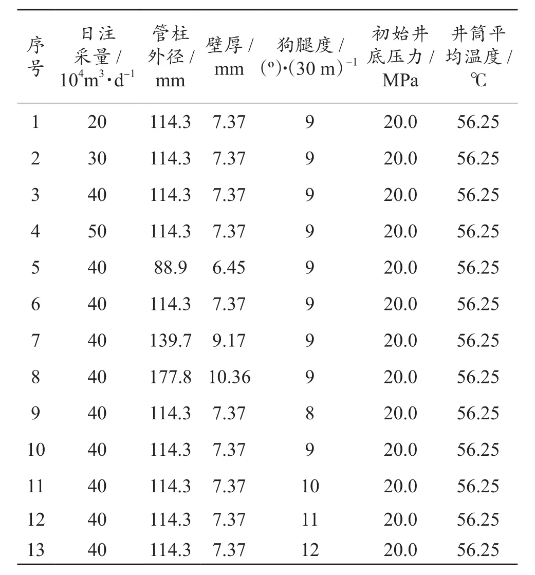
表1 算例工况设置Table 1 Working condition setting
2.2 计算结果分析
Analysis on calculation results
当不考虑固体颗粒冲蚀时,储气库油管柱冲蚀损坏的原因是天然气在高速流动和压力变化条件下引起局部洞穴型腐蚀。储气库注气过程中,除由注采压差引起的近壁静压外,管柱弯曲将导致管壁法向方向的气体速度分量迅速减小,此时气体动能转化为作用于管壁的机械能,表现为管柱近壁压力增大,该压力称为全受阻压力(简称全压或总压,p总),它与未受扰动处的压力(即静压,p静)之差,称为动压(p动),动压是管柱产生压力冲蚀的重要原因。日注采量为40×104m3/d,井斜角为23.6º(最大狗腿度9(º)/30 m),采用 Ø114.3 mm×7.37 mm 油管时,油管柱内天然气的截面速度、涡量及近壁压力计算结果如图2所示。
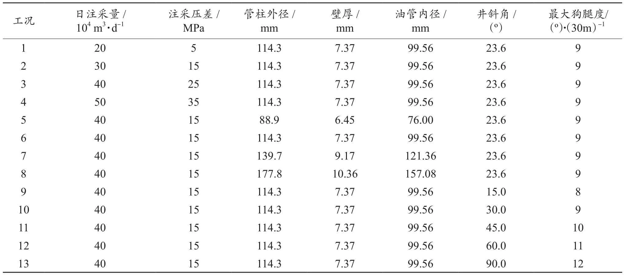
表2 模拟试验工况Table 2 Working condition of simulation experiment
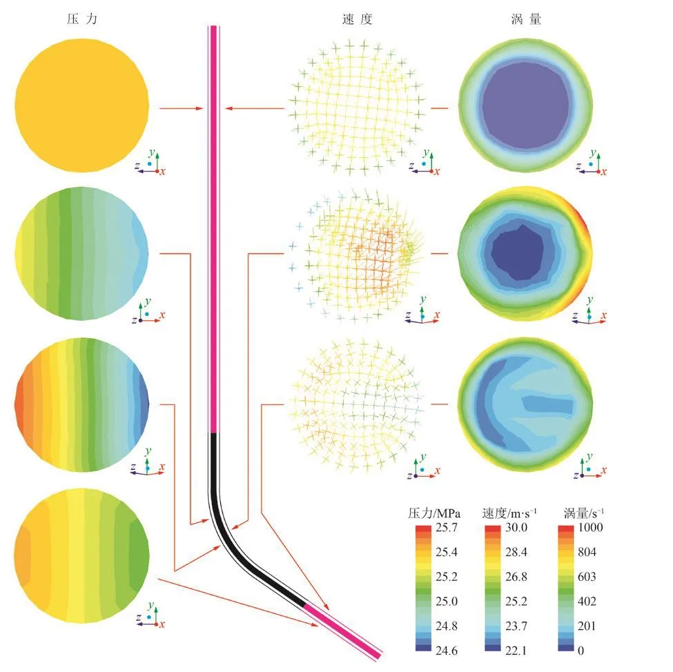
图2 油管内天然气速度(a)、涡量(b)及静压(c)截面云图Fig. 2 Cross-section cloud chart of gas velocity (a), vorticity (b)and static pressure (c) inside the tubing
从图2可以看出:(1)油管柱内气体截面速度自油管中心到管壁逐渐减小;气体从流入端到流出端过程中,弯曲内侧速度先增大后减小,弯曲外侧速度先减小后增大。(2) 油管柱内气体截面涡量自中心到管壁逐渐增大;进入造斜段后,管柱内侧涡量明显增大,这是因为离心作用形成二次旋流在此处产生的压力真空,形成漩涡分布,漩涡的存在使分子碰撞加剧,造成机械能损失。(3)储气库管柱近壁压力沿程分布受井身结构影响。天然气流入造斜段时,管柱弯曲外侧壁压力增大,弯曲内侧壁压力减小;流出造斜段时,管柱弯曲外侧壁压力减小,弯曲内侧壁压力增大,并随狗腿度减小逐渐趋于平稳。(4)天然气进入造斜段后,静压得到释放,速度增加,动压随之增大。(5) 冲蚀位置出现在造斜段管柱弯曲外侧。
2.3 影响因素分析
Analysis on in fl uential factors
2.3.1 压差 研究管柱规格和井身结构一定(井斜角23.6º,Ø114.3 mm×7.37 mm油管)时管柱近壁压力随注采压差的变化规律。图3为地下储气库井筒底部压力恒定(20 MPa),注采压差分别为5 MPa、10 MPa、15 MPa和20 MPa时的造斜段油管柱压程比变化规律曲线。从图3可以看出,试验压差从5 MPa提高到20 MPa的过程中,流入端弯曲外侧和内侧的平均压程比明显增大,变化率为325%和257%,流出端弯曲外侧和内侧的平均压程比明显增大,变化率为425%和322%。
2.3.2 井斜角 研究管柱规格和日注采量一定(Ø114.3 mm×7.37 mm油管,注气量40×104m3/d)时管柱近壁压力随井斜角变化的规律。图 4为井斜角分别为 0º(直井)、15º、30º、45º、60º和 90º(水平井)时的造斜段油管柱压程比变化规律。从图4可以看出,井斜角从0º(直井)增大到90º(水平井)过程中,流入端弯曲外侧和内侧的平均压程比增大,变化率分别为14.7%和57.5%,流出端弯曲外侧和内侧的平均压程比减小,变化率分别为-12.8%和-69.2%。
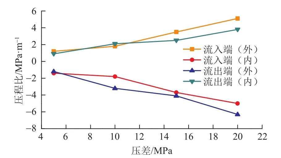
图3 管柱造斜弯曲段流入流出端压程比随压差变化规律Fig. 3 Effect of pressure difference on the pressure range ratio between the infow end and the outfow end of the defecting bend section in the string
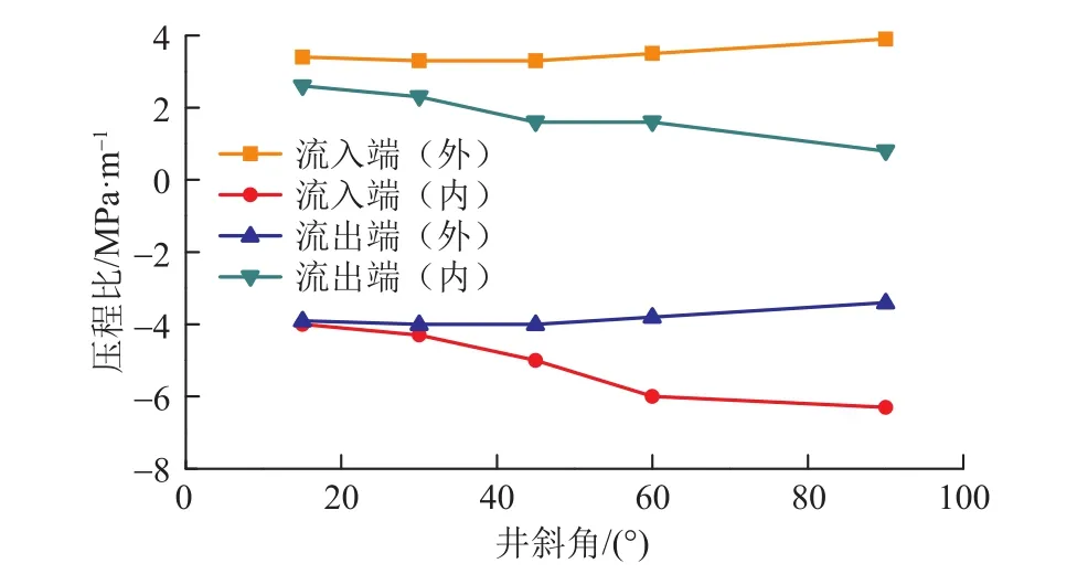
图4 管柱造斜弯曲段流入流出端压程比随井斜角变化规律Fig. 4 Effect of hole deviation angle on the pressure range ratio between the infow end and the outfow end of the defecting bend section in the string
2.3.3 油管内径 研究井斜角为23.6º(最大狗腿度9(º)/30 m)、注气量 40×104m3/d 时,油管内径变化(取油管规格分别为Ø88.9 mm×6.45 mm、Ø114.3 mm×7.37 mm、Ø139.7 mm×9.17 mm、Ø177.8 mm×10.36 mm)对气体压程比的影响规律,如图5所示。
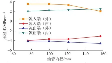
图5 管柱造斜弯曲段流入流出端压程比随油管内径变化规律Fig. 5 Effect of tubing ID on the pressure range ratio between the infow end and the outfow end of the defecting bend section in the string
从图5可以看出,油管内径从76 mm增加到157 mm时,流入端弯曲外侧和内侧的平均压程比减小,变化率分别为42.9%和22.5%,流出端弯曲外侧和内侧的平均压程比增大,变化率分别为12.2%和25.0%。
3 结论
Conclusions
(1) 油管柱内气体截面速度自油管中心到管壁逐渐减小;气体从流入端到流出端过程中,弯曲内侧速度先增大后减小,弯曲外侧速度先减小后增大。油管柱内气体截面涡量自中心到管壁逐渐增大;进入造斜段后,管柱内侧涡量明显增大。天然气流入造斜段时,管柱弯曲外侧壁压力增大,弯曲内侧壁压力减小;流出造斜段时,管柱弯曲外侧壁压力减小,弯曲内侧壁压力增大,并随狗腿度减小逐渐趋于平稳。气体冲蚀位置出现造斜段管柱弯曲外侧壁上。
(2) 随着注采压差增大,流入端和流出端弯曲外侧和内侧平均压程比均明显增大;随着井斜角增大,流入端弯曲外侧和内侧的平均压程比增大,流出端弯曲外侧和内侧的平均压程比减小;随着油管内径增大,流入端弯曲外侧和内侧的平均压程比减小,流出端弯曲外侧和内侧的平均压程比增大。
(3) 过高的日注采气量将引起定向储气库井造斜段管柱整体载荷水平的提高,过大的狗腿度和过大的油管内径将分别造成造斜段管柱流入端和流出端的压程比上升,造成该位置出现气体冲蚀现象。实际生产中,建议采用“低产量、稳压差”的生产理念,满足产量要求的情况下优先选择小尺寸油管,对狗腿度较大的井下油管气蚀情况应进行重点监控。
[1] PATANKAR SV. Numerical heat transfer and fluid flow[M]. Hemisphere Publishing Corporation, Fremont, CA,1980.
[2] WILCOX D C. Turbulence modeling for CFD[M].DCW Industries, La Canada, CA, 2006.
[3] STACK M M, ABDELRAHMAN S M. A CFD model of particle concentration effects on erosion–corrosion of Fe in aqueous conditions[J]. Wear, 2011, 273(1): 38-42.
[4] SAVIDGE J L, STARLING K E, MCFALL R L. Sound speed of natural: SPE Gas Technology Symposium[C].Alberta, Canada, Society of Petroleum Engineers, 1988.
[5] SLETFJERDING, ELLING, GUDMUNDSSON, JON STEINAR. Friction factor directly from roughness measurements[J]. Journal of Energy Resources Technology, Transactions of the ASME, 2003, 125(2):126-130.
[6] MAZUMDER Q H, SHIRAZI S A, MCLAURY B.Experimental investigation of the location of maximum erosive wear damage in elbows[J]. Journal of Pressure Vessel Technology, 2008, 130(1): 244-254.
[7] MAZUMDER Q H, SHIRAZI S A, MCLAURY B.Mazumder Q H, Shirazi S A, Mclaury B S. Prediction of solid particle erosive wear of elbows in multiphase annular fow-model development and experimental validations[J].Journal of Energy Resources Technology, 2008, 130(2):220-254.
[8] DENG T, PATEL M, HUTCHINGS I, BRADLEY M A. Effect of bend orientation on life and puncture point location due to solid particle erosion of a high concentration flow in pneumatic conveyors[J]. Wear,2005, 258(1): 426-433.
[9] ZHANG H, TAN Y Q, YANG D M, TRIAS F X, JIANG S Q, SHENG Y, Oliva A. Numerical investigation of the location of maximum erosive wear damage in elbow:Effect of slurry velocity, bend orientation and angle of elbow[J]. Powder Technology, 2012, 217(3): 467-476.
[10] TAN Y Q, ZHANG H, YANG D M, JIANG S Q, SONG J H, SHENG Y. Numerical simulation of concrete pumping process and investigation of wear mechanism of the piping wall[J]. Tribology International, 2012,46(1): 137-144.
[11] LI R, YAMAGUCHI A, NINOKATA H. Computational fluid dynamics study of liquid droplet impingement erosion in the inner wall of a bent pipe[J]. Journal of Power & Energy Systems, 2010, 4(2): 327-336.
[12] SUZUK M, INABA K, YAMAMOTO M. Numerical simulation of sand erosion in a square-section 90-degree bend[J]. Journal of Fluid Science & Technology,2008, 3(7): 868-880.
[13] ZENG L, ZHANG G A, GUO X P. Erosion–corrosion at different locations of X65 carbon steel elbow[J].Corrosion Science, 2014, 85(4): 318-330.
[14] FERNG Y M. Predicting local distributions of erosion–corrosion wear sites for the piping in the nuclear power plant using CFD models[J]. Annals of Nuclear Energy, 2008, 35(2): 304-313.
[15] FERNG Y M, LIN B H. Predicting the wall thinning engendered by erosion–corrosion using CFD methodology[J]. Nuclear Engineering & Design,2010, 240(10): 2836-2841.
[16] ZHU H J, LIN Y H, ZENG D Z, ZHOU Y, XIE J, WU Y P. Numerical analysis of fow erosion on drill pipe in gas drilling[J]. Engineering Failure Analysis, 2012, 22(1):83-91.
[17] ZHU H J, WANG J, CHEN X Y, SHE J. Numerical analysis of the effects of fluctuations of discharge capacity on transient fow feld in gas well relief line[J].Journal of Loss Prevention in the Process Industries,2014, 31(31): 105-112.
[18] ZHU H J, Pan Q, ZHANG W L, FENG G, Li X. CFD simulations of fow erosion and fow-induced deformation of needle valve: Effects of operation, structure and fuid parameters[J]. Nuclear Engineering & Design, 2014,273(1): 396-411.
[19] 练章华,魏臣兴,宋周成,丁亮亮,李锋,韩玮. 高压高产气井屈曲管柱冲蚀损伤机理研究[J]. 石油钻采工艺,2012,34(1):6-9.LIAN Zhanghua, WEI Chenxing, SONG Zhoucheng,DING Liangliang, LI Feng , HAN Wei. Erosion damage mechanism of buckled tubing in high pressure and high production gas wells[J]. Oil Drilling & Production Technology, 2012, 34(1): 6-9.
[20] 王嘉淮,罗天雨,吕毓刚,薛承文,赵丽萍. 呼图壁地下储气库气井冲蚀产量模型及其应用[J]. 天然气工业,2012,32(2):57-59.WANG Jiahuai, LUO Tianyu, LV Yugang, XUE Chengwen, ZHAO Liping. Research and application of model of gas well erosion output of the Hutubi underground gas storage[J]. Natural Gas Industry,2012, 32(2): 57-59.
(修改稿收到日期 2017-05-25)
(编辑 景 暖)
Numerical simulation on the state of fl uids along the string of gas storage well
LIU Minggang1, WANG Jianjun2, YAN Yifei1, XIE Wei3, YANG Xiujuan1, YAN Xiangzhen1, ZHANG Yanru3
1. China University of Petroleum (Huadong), Qingdao 266580, Shandong, China;2. CNPC Tubular Goods Research Institute, Xi’an 710077, Shaanxi, China; 3. CNPC Huabei Oil field Company, Renqiu 062552, Hebei, China
To analyze the force applied on the string of gas storage well and determine the erosion position, it is crucial to fgure out the motion state of natural gas in the tubing string in the process of gas injection and production. In this paper, a physical model used to simulate the fowing process of natural gas along the tubing string of directional gas storage well was established on the basis of casing program and operation parameters. Then, the velocity and vorticity along the string and the distribution of pressure close to the wall in the defecting section were researched by means of numerical experiment. And fnally, the infuential laws of injection-production pressure difference, hole deviation angle and tubing ID on the pressure close to the wall of string were analyzed. It is indicated that the state of fuids inside the tubing string is affected by injection-production pressure difference and casing program, and the fow velocity of natural gas and its pressure close to the wall fuctuate the moment it fows into and out of the defecting section. The velocity and dynamic pressure along the string decrease as the well gets deep. Erosion point is located at the connection line between the radial line at the maximum dogleg angle and the central line of string from the infow end to the outfow end of defecting section. As the injection-production pressure difference increases, the average pressure range ratio between the outside and the inside of the bend at infow and outfow ends increases obviously. With the increasing of hole deviation angle, the average pressure range ratio between the outside and the inside ofthe bend at the infow end increases while that at the outfow end decreases. And with the increasing of tubing ID, the average pressure range ratio between the outside and the inside of the bend at the infow end decreases while that at the outfow end increases.
underground gas storage; directional well; defecting section; erosion; fuid mechanics calculation
刘铭刚,王建军,闫怡飞,谢巍,杨秀娟,闫相祯,张艳茹.地下储气库井管柱沿程流体状态数值模拟[J] .石油钻采工艺,2017,39(4):449-454.
TE38
A
1000 – 7393( 2017 ) 04 – 0449 – 06
10.13639/j.odpt.2017.04.010
:LIU Minggang, WANG Jianjun, YAN Yifei, XIE Wei, YANG Xiujuan, YAN Xiangzhen, ZHANG Yanru. Numerical simulation on the state of fuids along the string of gas storage well[J]. Oil Drilling & Production Technology, 2017, 39(4): 449-454.
国家自然科学基金资助课题“基于应变控制的热采井套管试验及安全可靠性研究”(编号:51274231);国家自然科学基金资助课题“基于多目标约束优化方法的页岩气储层微裂缝分析及压裂缝网扩展机理研究”(编号:51374228)。
刘铭刚(1990-),博士研究生,从事油气工程力学、机械强度及可靠性方面的研究工作。通讯地址:(266580)山东省青岛市黄岛区长江西路66号中国石油大学(华东)储运与建筑工程学院。E-mail: liuminggang0303@126.com
