Optical pumping nuclear magnetic resonance system rotating in a plane parallel to the quantization axis∗
2017-08-30ZhiChaoDing丁志超JieYuan袁杰HuiLuo罗晖andXingWuLong龙兴武
Zhi-Chao Ding(丁志超),Jie Yuan(袁杰),Hui Luo(罗晖),and Xing-Wu Long(龙兴武)
College of Optoelectronic Science and Engineering,National University of Defense Technology,Changsha 410073,China
Optical pumping nuclear magnetic resonance system rotating in a plane parallel to the quantization axis∗
Zhi-Chao Ding(丁志超),Jie Yuan(袁杰)†,Hui Luo(罗晖),and Xing-Wu Long(龙兴武)‡
College of Optoelectronic Science and Engineering,National University of Defense Technology,Changsha 410073,China
A model of an optical pumping nuclear magnetic resonance system rotating in a plane parallel to the quantization axis is presented.Different coordinate frames for nuclear spin polarization vector are introduced,and theoretical calculation is conducted to analyze this model.We demonstrate that when the optical pumping nuclear magnetic resonance system rotates in a plane parallel to the quantization axis,it will maintain a steady state with respect to the quantization axis which is independent of rotational speed and direction.
optical pumping,nuclear magnetic resonance,spin polarization
1.Introduction
The concept of nuclear magnetic resonance(NMR)was proposed by Rabi in 1938.[1]Later,it was improved in theory by Bloch.[2,3]Since then,great progress has been made in NMR.Now,it is widely used in many significant areas such as biological medicine,[4]analytical chemistry,[5,6]fundamental physics,[7–9]and inertial navigation.[10,11]
For a typical optical pumping NMR system shown in Fig.1(a),the alkali-metal vapor and noble gas are filled in a cell.A constant magnetic field B0which determines the direction of quantization axis is applied along the Z-axis. Pump light parallel to B0is used to polarize the alkali-metal atoms.[12]Through the spin exchange between alkali-metal atom and noble gas nuclei,the spin polarization is transferred from the electron of alkali-metal atom to the nuclei of noble gas.[13]An oscillating magnetic field Bosperpendicular to B0is applied along the X-axis to excite the nuclear transitions.When this system reaches a steady state,it can be utilized to measure the rotation rate of the system about the quantization axis.[10]Because of this,one representative application of NMR is nuclear magnetic resonance gyroscope (NMRG),which can achieve navigation-grade precision and chip scale simultaneously and is widely regarded as a potential candidate for the high-precision micro inertial navigation in the future.[14]Not long ago,navigation-grade NMRG with the size of 10 cm3was reported by Northrop Grumman.[15]
Since the instability in amplitude of a signal influences the measuring precision of its frequency,and in order to determine the rotation rate of an optical pumping NMR system with high precision,a necessary condition where the system maintains a steady state with respect to the quantization axis is required.[16]When the system rotates around the quantization axis,which is shown in Fig.1(a),only the direction of Boswill rotate with the system.Through feedback control,thatnecessary condition can be satisfied and the rotation rate can be measured with high precision.[17]However,when the system rotates in a plane parallel to the quantization axis,which is shown in Fig.1(b),the directions of B0and pump light rotate with the system as well,while the alkali-metal atoms and noble gas cannot perceive the rotation.To our knowledge,it has not been proved theoretically whether the system can remain steady with respect to the quantization axis.
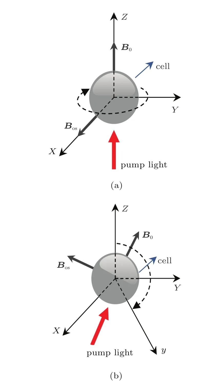
Fig.1.(color online)Optical pumping NMR system rotating in a plane(a) perpendicular to the quantization axis or(b)parallel to the quantization axis.
For the NMRG(G1)in a three-axis inertial navigation system which consists of three NMRGs,its spin axis is actually the quantization axis which is along the direction of B0applied to G1 constantly,and G1 can only tract the rotations around the spin axis.[15]The spin axis of G1 is assumed to be along the Z-axis initially as shown in Fig.2.Rotations of the system around the Z-axis will be tracked by G1.When the system rotates in a plane parallel to B0,the rotation will be tracked by other two NMRGs.After the system rotates in a plane parallel to B0for a period of time,and the spin axis of G1 rotates to a certain orientation(z1-axis)as shown in Fig.2, G1 needs to be able to respond to the rotation around the z1-axis with high precision immediately in many practical cases, such as the three-axis inertial navigation system mounted on a vehicle with quick changes of direction,which means quick changes of the spin axis of the gyroscope.[18]So,if an NMRG needs a period of time comparable to the relaxation time of nuclear ensemble to reach steady after rotating to a certain orientation,the NMRG will keep a relatively low precision for about tens of seconds,[15]and it will be a big problem when an NMRG is applied to a three-axis inertial navigation system eventually.
In this paper,we demonstrate that an optical pumping NMR system will remain steady with respect to the quantization axis when it rotates in a plane parallel to the quantization axis,regardless of any rotational speed and direction.

Fig.2.(color online)Spin axes of an NMRG before and after rotating in a plane parallel to the quantization axis.
2.Theory
2.1.Analytical solution for an optical pumping NMR system
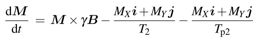
From a macroscopic view,the nuclear spin ensemble is usually described by the magnetization vector M in NMR, which isrepresented as(MX,MY,MZ)Tin the coordinate frame X Y Z.When there is no pump light and a constant magnetic field is applied along the Z-axis,under the influence of external magneticfield B,the evolution of the magnetization vector is given by the Bloch equation[3]

Here,i,j,and k respectively represent the unit vectors along the X,Y,and Z axes,γ is the gyromagnetic ratio of atomic nuclei,T2is the transverse relaxation time of nuclear spin polarization,T1is the longitudinal relaxation time of nuclear spin polarization,and M0is the magnetization under the equilibrium state.Assume that the pump light along the Z-axis is applied,equation(1)becomes[19,20]
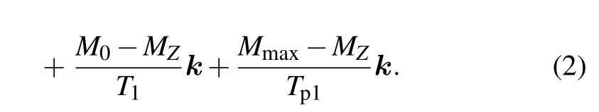
Here,Tp2is designated as a time constant for the relaxation effect on the transverse magnetization due to the pump light.[20]Tp1is a time constant for the optical pumping process which attempts to increase the magnitude of the magnetization along the Z-axis.[19]Mmaxis the magnetization when the nuclear spin ensemble is completely polarized by the optical pumping.
In order to simplify the form of Eq.(2),the spin polarization vector P for the nuclear spin ensemble is used to replace M,which satisfies P=M/Mmaxand is represented as(PX,PY,PZ)Tin the laboratory coordinate frame X Y Z as shown in Fig.3.[12]As M0is tiny,it can be neglected when the pump light is applied.[12]By setting 1/τ2=1/T2+1/Tp2, 1/τ1=1/T1+1/Tp1,and P0=τ1/Tp1,it is easy to obtain

For a typical optical pumping NMR system B=B0+ Bos,where B0=B0k,Bos=2B1cos(ω0t)i and ω0=γB0. Substituting these conditions into Eq.(3),it can be rewritten
as

where ω1=γB1.

Fig.3.Spin polarization vector in the laboratory coordinate frame X Y Z.
The conventional method to simplify the computation of Eq.(4)is adopted.The Bosis divided into a clockwise component and a counterclockwise component with respect to the Z-axis.The clockwise component is Bc=B1cos(ω0t)i−B1sin(ω0t)j,and the counterclockwise component is Bcc= B1cos(ω0t)i+B1sin(ω0t)j.As the counterclockwise component has little influence on the evolution of P unless B1is quite large,it can be ignored by using the rotating-wave approximation.[2]Since Bcis a rotating oscillating magneticfield,by setting
Equation(4)can be rewritten as

When this NMR system reaches a steady state,the above equations are all equal to zero.The stationary solutions can be easily obtained as follows:

From the above analysis,we obtain the stationary state of a typical optical pumping NMR system when its initial quantization axis is along the Z-axis as shown in Fig.2.For proving that the system remains steady when it rotates in the plane parallel to the quantization axis,we need to obtain the spin polarization vector when this system rotates and compare it with the initially achieved stationary spin polarization vector.
2.2.Analytical solution for an optical pumping NMR system rotating in a plane parallel to the quantization axis
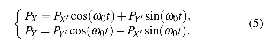
Assume that this NMR system has been steady before t=t0,and it starts to rotate in the y–Z plane with the angular rate of ωrat t=t0,which is shown in Fig.1(b).As the NMR system rotates in the y–Z plane,it is beneficial for our demonstration to represent the spin polarization vector in a new laboratory coordinate frame xyZ shown in Fig.4.In the coordinate frame xyZ,the spin polarization vector is represented as (Px,Py,PZ)T.Define that the angle between x-axis and X-axis is φ1,which is shown in Fig.4.According to Eqs.(5)and (7),the initial spin polarization vector when the NMR system starts to rotate at t=t0can be easily obtained as follows:
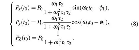
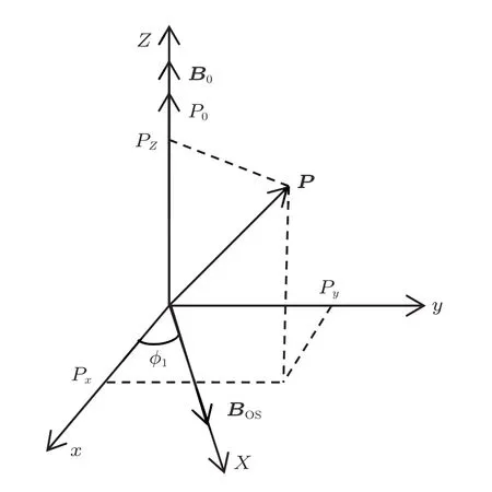
Fig.4.Spin polarization vector in the laboratory coordinate frame xyZ.
When this NMRsystem rotates around the x-axisin the y–Z plane,the directions of B0,Bos,and pump light will rotate around the x-axis.For simplifying the following analysis,a rotating coordinate frame xy′z which rotates clockwise around the x-axis with a frequency of ωris introduced and shown in Fig.5.The directions of B0and pump light are along the z-axis throughout the rotation,while Bosis always perpendicular to the z-axis.In the coordinate frame xy′z,the spin polarization vector is represented as(Px,Py′,Pz)Tand given by

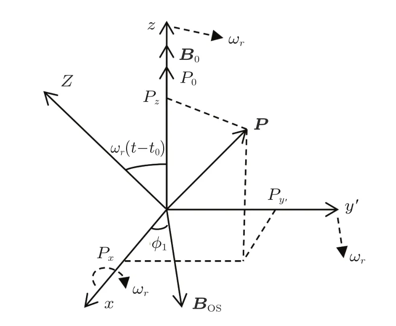
Fig.5.Spin polarization vector in the rotating coordinate frame xy′z.
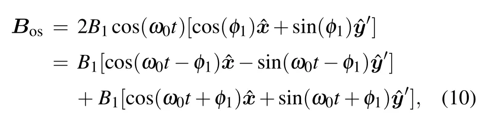
Since Bosis always perpendicular to the z-axis,it is always in the x–y′plane.The angle between x-axis and Bosis φ1constantly as the direction of Bosrotates around the x-axis. So,Boscan be rewritten as
Though this NMR system rotates around the x-axis when t≥t0,the evolution of spin polarization vector at any time satisfies the Bloch equation.The directions of pump light and quantization axis are always along the z-axis at any time when t≥t0,while the directions of pump light and quantization axis are along the Z-axis when t<t0.So,through the same derivation as for Eq.(3),the evolution of spin polarization vector at any time when t≥t0can be given by
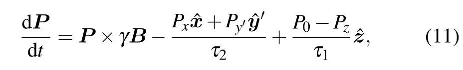
as
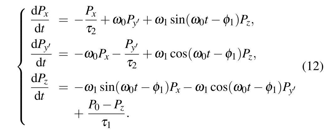
Since Bc′is a rotating oscillating magnetic field,by setting
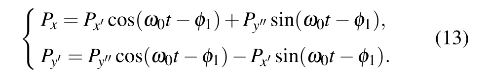
Equation(12)can be rewritten as
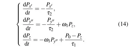
When this NMR system reaches a steady state,the above equations are all equal to zero,and the stationary solutions can be obtained as follows:
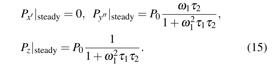
Substituting Eqs.(9)and(13)into Eq.(8),the initial solutions of Px′,Py′,and Pzwhen this NMR system starts to rotate at t=t0are given by
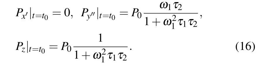
We can find from Eqs.(15)and(16)that the initial solutions at t=t0and the stationary solutions of Px′,Py′,and Pzto Eq.(14)are identical.In addition,substituting Eq.(16)into Eq.(14),we can obtain

Using the knowledge of differential equation in mathematics,the solutionsof Px′,Py′,and Pzto Eq.(14)are constants as follows:

From the results of Eq.(18),we can find that with respect to the rotating quantization axis(z-axis),this NMR system remains steady when t≥t0,which is not dependent on φ1nor ωr.If this NMR system rotates with any angular rate of ωrfor a period of time and then it stops rotating,and the quantization axis is now along the z1-axis as shown in Fig.2,through the same derivation as for Eq.(3),the evolution of spin polarization vector in a new laboratory coordinate frame x1y1z1is given by
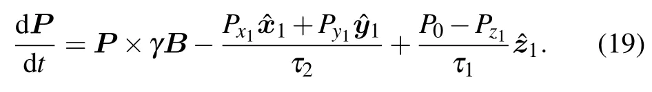
According to the results of Eq.(18),by setting
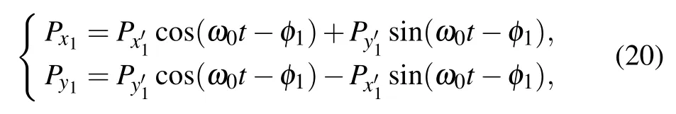
we can obtain

By comparing Eqs.(21)and(19)with Eqs.(7)and(3), we can deduce that this NMR system will be in a steady state with respect to the new spin axis after it has stopped rotating in a plane parallel to the quantization axis.
3.Discussion
We can find from the above theoretical calculation that after a typical optical pumping NMR system reaches a steady state,the spin polarization along the quantization axis is a constant no matter how this NMR system rotates,and that is why it can maintain steady.A physical picture of this phenomenon is that the steady state of this NMR system is very special.When this NMR system reaches a steady state and starts to rotate in a certain plane,under the influences of pump light and external magnetic field,both of which rotate with the system,the projection of spin polarization vector on the new quantization axis happens to keep unchanged.
After an optical pumping NMR system reaches a steady state,if it rotates in a plane parallel to the quantization axis with a certain angular rate for a period of time and the quantization axis is now along the z1-axis,then the system will remain steady and it can measure the rotation about the z1-axis. If the system continues to rotate in another plane parallel to the new quantization axis with another angular rate for a period of time and the quantization axis is now along the z2-axis, then the system will remain steady and it can measure the rotation about the z2-axis,since the system is already a steady state when it starts to continue to rotate.
Consequently,when an NMRG is applied to a three-axis inertial navigation system,it can remain steady with respect to the quantization axis when the system rotates in any plane with any angular rate.After the NMRG reaches a steady state and then rotates to a certain orientation,it can measure the rotation about the quantization axis with the same precision as before.
4.Conclusions
When an optical pumping NMR system rotates in a plane parallel to the quantization axis,the directions of applied magnetic fields and pump light will rotate with the system,while the alkali-metal atoms and noble gas cannot perceive the rotation.Even so,we demonstrate that after this system reaches a steady state,it will maintain steady with respect to the quantization axis when it rotates in a plane parallel to the quantization axis,regardless of any rotational speed and direction. Therefore,for an NMRG applied to a three-axis inertial navigation system,rotation in a plane parallel to the quantization axis has no influence on its measuring precision.
[1]Rabi I I,Zacharias J R,Millman S and Kusch P 1938 Phys.Rev.53 318
[2]Bloch F and Siegert A 1940 Phys.Rev.57 522
[3]Bloch F 1946 Phys.Rev.70 460
[4]Hane F T,Li T,Smylie P,Pellizzari R M,Plata J A,DeBoef B and Albert M S 2017 Sci.Rep.7 41027
[5]Wagner L,Kalli C,Fridjonsson E O,May E F,Stanwix P L,Graham B F,Carroll M R J and Johns M L 2016 Meas.Sci.Tech.27 105501
[6]Wang S and Chen L 2016 Chin.Phys.B 25 018202
[7]Bulatowicz M Griffith R,Larsen M,Mirijanian J,Fu C B,Smith E, Snow W M,Yan H and Walker T G 2013 Phys.Rev.Lett.111 102001
[8]Anjusha V S,Hegde S S and Mahesh T S 2016 Phys.Lett.A 380 577
[9]Kammerlander P and Anders J 2016 Sci.Rep.6 22174
[10]Donley E A 2010 Sensors,2010 IEEE,November 1-4,2010,Waikoloa, USA,p.17
[11]Zhang D W,Xu Z Y,Zhou M and Xu X Y 2017 Chin.Phys.B 26 023201
[12]Happer W 1972 Rev.Mod.Phys.44 169
[13]Walker T G and Happer W 1997 Rev.Mod.Phys.69 629
[14]Larsen M and Bulatowicz M 2012 2012 IEEE International Frequency Control Symposium Proceedings,May 21-24,2012 Baltimore,USA, p.1
[15]Meyer D and Larsen M 2014 Gyroscopy and Navigation 5 75
[16]Prikhodko I P,Trusov A A and Shkel A M 2014 2014 International Symposium on Inertial Sensors and Systems(ISISS),February 25-26, 2014,Laguna Beach,USA,p.1
[17]Eklund E J 2008 Microgyroscope Based on Spin-polarized Nuclei (Ph.D.Thesis)(Irvine:University of California,Irvine)
[18]Greenspan R L 1995 Navigation 42 165
[19]Cohen-Tannoudji C,Dupont-Roc J,Haroche S and Lalo¨e F 1970 Rev. Phys.Appl.5 95
[20]Seltzer S J 2008 Developments in Alkali-metal Atomic Magnetometry(Ph.D.Thesis)(Princeton:Princeton University)
10 May 2017;revised manuscript
3 June 2017;published online 11 August 2017)
10.1088/1674-1056/26/9/093301
∗Project supported by the National Natural Science Foundation of China(Grant No.61475192).
†Corresponding author.E-mail:jieyuan@nudt.edu.cn
‡Corresponding author.E-mail:xwlong110@sina.com
©2017 Chinese Physical Society and IOP Publishing Ltd http://iopscience.iop.org/cpb http://cpb.iphy.ac.cn
猜你喜欢
杂志排行

Chinese Physics B的其它文章
- Improved control for distributed parameter systems with time-dependent spatial domains utilizing mobile sensor actuator networks∗
- Geometry and thermodynamics of smeared Reissner–Nordström black holes in d-dimensional AdS spacetime
- Stochastic responses of tumor immune system with periodic treatment∗
- Invariants-based shortcuts for fast generating Greenberger-Horne-Zeilinger state among three superconducting qubits∗
- Cancelable remote quantum fingerprint templates protection scheme∗
- A high-fidelity memory scheme for quantum data buses∗