Power System Design and Analysis for Ocean Power Plant
2017-05-19DUANChunmingZHANGFanCUIHansongCHENMo
DUAN Chunming, ZHANG Fan, CUI Hansong, CHEN Mo
(1.State Grid Jibei Electric Economic Research Institute, Haidian District, Beijing 100038, China;2.State Grid Communication Construction Branch, Beijing 100052, China)
Power System Design and Analysis for Ocean Power Plant
DUAN Chunming1, ZHANG Fan1, CUI Hansong1, CHEN Mo2
(1.State Grid Jibei Electric Economic Research Institute, Haidian District, Beijing 100038, China;2.State Grid Communication Construction Branch, Beijing 100052, China)
The power system, the core part of the ocean power plants, should meet the requirements of the power generation devices (tide and wave energy power generation device) for grid integration, and safe and reliable transmission in the real-time conditions. This paper makes the technical analysis of the power generation devices (collection system and transmission system), including their economy and reliability, and provides the technical basis for the construction of domestic ocean power plants or testing fields in combination with practical engineering experience. And according to the overseas relevant study of the ocean power plant and the offshore wind farm, it also formulates the topological structure of collection system of the new generation device, and presents the composition of ocean power system. Considering the ocean special environmental factors and ocean power generation characteristics, it analyzes and compares the transmission system design for ocean power plants.
ocean energy; power plant; power system; power collection system
1 Introduction
Under the pressure of energy saving and environment protection and with the acceleration of conventional energy consumption, our country is implementing the new energy development strategy. As an important renewable energy, development and utilization of ocean energy necessarily become hotspot and cutting-edge technology in energy related research. Ocean energy resources are rich in our country, and economically developed coastal areas has a high electricity consumption. What’s more, island regions are suffering from severe lack of electricity, so it is necessary to accelerate the development and application of ocean energy generation technology and the construction of ocean energy generating site in our country[1].
At present, some leading European countries in the development of ocean energy have built ocean energy test sites to test and verify conversion devices for wave energy and tidal current energy and related technology, which will be applied to the business operations soon[2]. However, there is some difference between electrical systems of ocean energy test site and ocean energy generation site. Ocean energy generation site requires stable and sustainable power generation and the ability to provide electricity for load on shore; Test site are mainly used to test and verify performance of power generation devices. Only during testing does the power system stays in operating mode[3].
The power system of ocean energy generation site is the core part of the site which contributes to achieve the ultimate goal of generation site. The power system should meet the requirements of grid-connected electricity generation under real sea state and safe and reliable power delivery of ocean energy generation devices (tidal current energy and wave energy power generating devices). At present, there are no domestic ocean energy test and generation sites. In order to design and research domestic power system of ocean energy generation site, it is necessary to draw lessons from foreign construction experience of ocean energy power generation test sites and mature power system of offshore wind farm, and take special environment and generation characteristics ocean energy into consideration to analyze the design scheme of power system of ocean energy generation site at the same time.
2 Power System Configuration of Electricity Generating Site
Power system of ocean energy generating site, of which the objects of study are wave energy and tidal current energy, consists of five basic components, namely, ocean energy power plant, electricity acquisition system of power generating devices, transmission systems, shore-based distribution systems, and grid connection systems, as are shown in Figure 1. Feasibility, reliability and economy are taken into account during process of design and analysis, which briefly assess economy and reliability of electricity acquisition system of power plant, transmission system, and a series of study scheme of power system of marine energy generating site has been formulated according to practical experience in engineering.
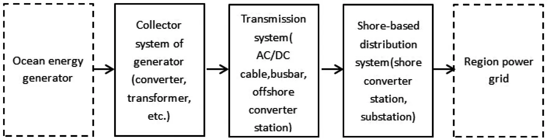
Fig.1 Analysis Scheme of Power System of Ocean Energy Power Plant
Components of ocean energy generating site are shown in Figure 2, which include the generation area, electricity acquisition systems, and distribution systems. Generation area includes marine energy generating devices, converters, onboard transformers, submarine cables, etc.; Electricity acquisition system includes submarine cables, off-shore platforms, converter station, etc.; Shore-based distribution system includes step-up substation, on-shore converter stations, and other energy storage devices. Secondary system mainly includes monitoring equipment and protection systems.

Fig.2 Construction of Ocean Energy Test Site
3 Conversion devices
In electricity acquisition topology of generating units, parallel constraint exists in connection of AC transmission line from the output of each electricity generating device. Converter system consists of AC / DC conversion devices, DC / DC conversion devices and grid-connection inverters. Electricity generated by wave energy and tidal current energy generators is firstly rectified, and then connected to DC side forming a generating unit, which eliminate the difference of frequency and phase angle, and also increases the energy output.
The main functions of AC / DC conversion devices are as follows:
(1) Convert AC power with irregular voltage amplitude and frequency generated by marine energy generators to DC power, which ensures the circulation of power flow channel of tidal current energy generating units;
(2) Enable the simulation of all kinds of common short circuit and open circuit faults;
(3) Capable of common over / under voltage protection, over / under frequency protection.
The main functions of DC/ DC conversion devices are as follows:
(1) Smooth power output fluctuations of tidal current energy and wave energy and deviation of grid-connection power, achieving a smooth adjustment of power in the system;
(2) Voltage supporting of DC bus of back to back converter system to effectively prevent voltage collapse.
The main functions of grid-connected inverter are as follows:
(1) Power adjustment of inverter side, control real power and reactive power independently;
(2) P / Q mode and V / F mode in operation the inverter side;
(3) Tune the rated capacity, voltage and power factor of the inverter side to a constant.
Design of converter system depends on transmission plan of submarine cable. Power can be transmitted by DC submarine cable or AC submarine cable after converted by inverter to AC power. When AC submarine transmission system shown in Figure 3 is chosen, electricity acquisition system of conversion devices shown in Figure 4 and shore-based power distribution system shown in Figure 5 which are based on AC submarine transmission system should be adopted.
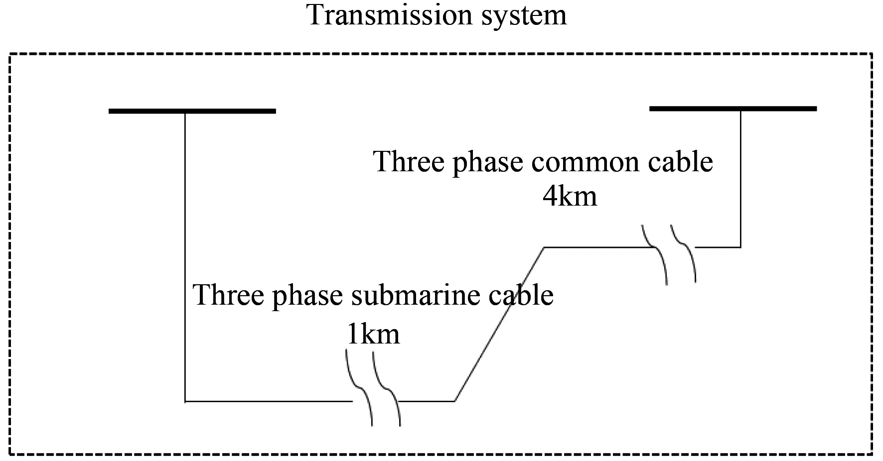
Fig.3 AC Submarine Electricity Transmission System

Fig.4 Electricity Acquisition System of Conversion Devices Based on AC Submarine Transmission System

Fig.5 Shore-Based Distribution System Based on AC Submarine Transmission System
In Figure 4, the form of ocean energy generating units is "a transformer connected to a generator", but if generator capacity is relatively small, transformer can be shared by two or more generators.
4 Acquisition System Topology of Generating Units
4.1 Electricity Acquisition Topology Inside Electricity Generation Site
It is necessary to choose a reasonable layout of electricity acquisition system when several ocean energy generating devices of the same type are connected to the grid simultaneously. Using construction experience of offshore wind electricity site, research and analysis into radial layout, Circular Layout and star layout are conducted[4-6].
4.1.1 Radial Layout
As shown in Figure 6, the radial layout is the simplest "serial" wiring. A series of generators are connected to the same medium voltage submarine cable, power are transmitted to the bus bar by the medium voltage submarine cable. The layout has simple structure and low investment cost, but without high reliability. If faults occur in somewhere of the submarine, the entire medium voltage cable will have to be cut and all ocean energy generators connected to it will stop operation.
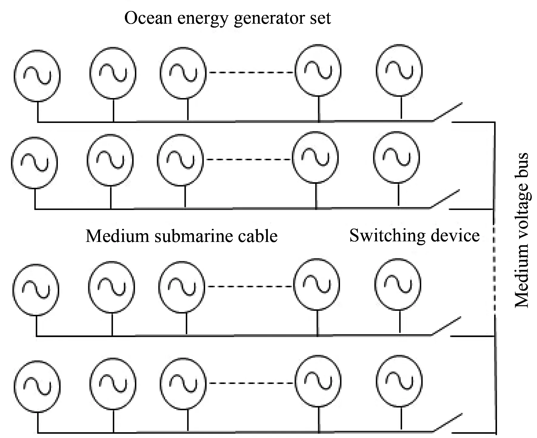
Fig.6 Radial Layout
4.1.2 Circular Layout
Circular layout requires cable of higher specification and longer length in comparison to the radial layout, and therefore the cost is higher. But it has some redundancy, which makes it possible to redistribute the power flow and enable generating units operate normally as many as possible when fault occurs somewhere in the cable. Circular layout can be divided into three classes: unilateral ring, bilateral ring and composite ring.
Compared with radial layout, unilateral ring connects the generating units at the end of the cable back to the medium voltage bus by adding a redundant cable, as is shown in Figure 7. If fault occurs in somewhere of the cable, the cable can be removed by the switch device on the cable to ensure the normal operation of the generating units. This layout can improve the operating reliability of the power system, but it increases the number of switching devices which results in complexity in operation and increases the redundant cable leading to higher cost. Therefore, different switching configurations are designed to reduce complexity and cost[7].

Fig.7 Unilateral Ring Layout
As is shown in Figure 8, bilateral ring connects the generating units at the end of the two adjacent cables through a redundant cable. The number of generators connected to the same cable doubles, so the rated power of cables also doubles, which increase the investment.
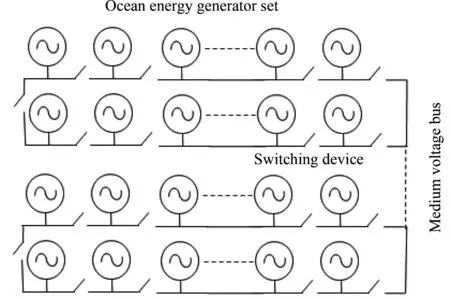
Fig.8 Bilateral Ring Layout
A composite annular ring is a combination of unilateral ring and bilateral ring. It connects generating units at the end of several adjacent cables, and then connects them back to the medium voltage bus by a redundant cable, as is shown in Figure 9. The composite ring layout can reduce the number of redundant cable compared with unilateral ring layout and also can reduce rated capacity compared to bilateral ring layout, but it increases the number of switching devices.

Fig.9 Composite Ring Layout
4.1.3 Star Layout
Electricity acquisition system in star layout is of circular arrangement, as is shown in Figure 10. It is suitable for sea area which has frequent changes in the direction of water flow. The water flow of typical sea area is basically stable, which is suitable for the layout of wave energy generators of point absorption, and not suitable for layout of tidal current energy generators. Due to the cable of connecting point in star layout only connects to one unit, so its reliability is higher than the chain-like structure, and lower than the ring structure[7]. At present, the vast majority of wind farms built are of star configuration. The maximum number of wind generators connecting wiring in star layout depends on the maximum rated capacity of the cable.
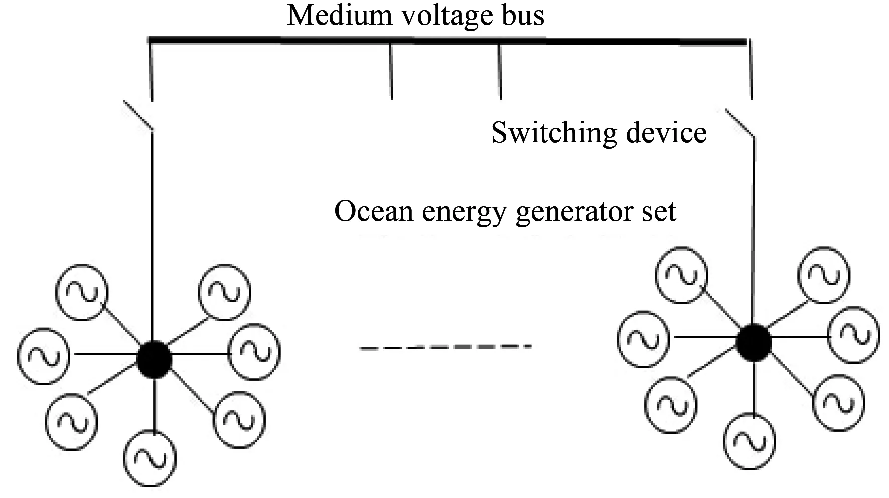
Fig.10 Star Layout
4.2 Electricity Acquisition Topology Between Electricity Generating Sites
In general, sea state which is suitable for wave energy generation is not suitable for tidal current energy generation and vice versa. Therefore, power generating areas of the two aforementioned types should not be deployed in the same area. Electricity acquisition plan between generating units should take both situations into account.
4.2.1 Centralized Connection
When there are different types of marine energy generating devices in the ocean energy electricity generating site to be connected to the grid, in order to make effective use of the submarine cable, a bus bar is utilized to transmit electricity in a centralized way, as is shown in Figure 11.
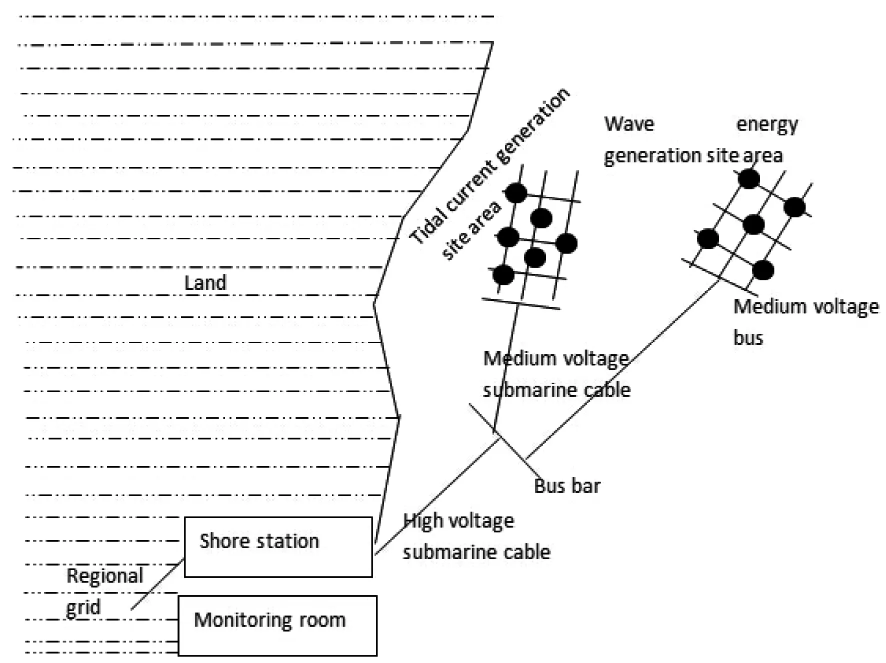
Fig.11 Centralized Access
Flowing through collector bus, the electricity generated by the wave energy and tidal current energy generating devices is sent to shore substation and power distribution systems together. The advantages of this kind of wiring for grid connection include saving submarine cable, making full use of transmission capacity of submarine cable and offshore converter station is not needed to be set up as well; the drawback is that when the AC transmission line needed to be connected, parallel constrains is needed to be met, namely: identical frequency, identical phase angle, and identical amplitude. Otherwise, power circulation begin paralleled lines will be generated. When the DC transmission lines are to be connected, just make sure the DC voltages are identical.
4.2.2 Decentralized Connection
Offshore bus bars are not included in wave energy and tidal current energy field regions in decentralized connection. Wave energy and tidal current energy generating sites are connected separately to the shore-based power distribution system in a direct way, as is shown in Figure 12. The advantage of decentralized connection plan is without requirements of parallel constraints, therefore, both AC transmission and DC transmission can be applied. In the aforementioned connection plan, however, submarine transmission cables cannot be shared, which results in capacity waste.

Fig.12 Decentralized Access
4.3 Analysis of the recommended topology
Radial layout and star layout are categorized as no-backup wiring, while the rest are categorized as spare wiring. Redundant backup lines can improve the reliability of power generation site, but it requires more expensive submarine cables and increases to additional investment cost. Therefore, if there is no special requirements, it generally will not be considered. To enhance the stability, it is recommended to appropriately reduce the number of generating units in parallel connected to a single cable.
The tidal current energy is relatively stable that its velocity and flowing direction roughly stays the same. Therefore, topologies of electricity acquisition system for tidal current energy generator units are linear sequenced. Taking consideration of economy, radial convergence scheme is the most appropriate plan[8]. The phenomenon of peaks and valleys in wave leads to greater energy varying rate. What’ more, wave energy devices are of many different types. Depending on the wave energy device selection, if heave system device is chosen, there is no need to consider the wave direction and the arrangement is simple(star layout is enough); If oscillating water column type is chosen, the layout of the generators should focuses on the direction of wave to reduce the mutual influence. For they are usually arranged facing wave direction, radial layout is a choice. Alternative option is shown in Figure 13, which combines star layout with radial layout, ocean energy generating units are linked up like "string" by submarine cables and connect to the medium voltage bus through two feeders at the beginning part and the middle part. Necessary switching equipment, such as circuit breakers and isolation switches are installed on cables.
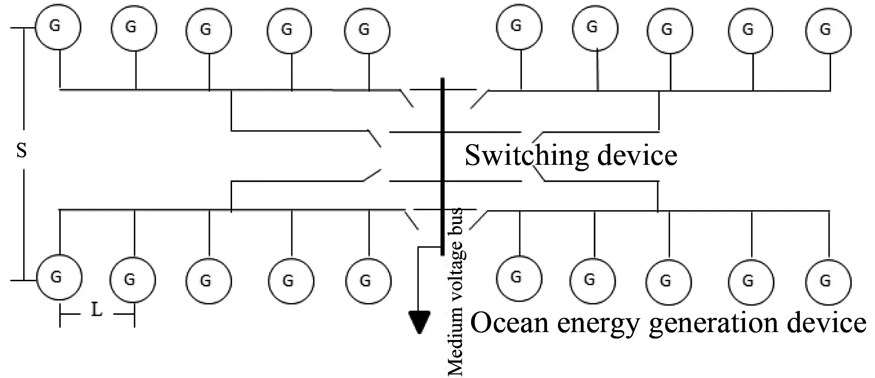
Fig.13 Recommended Topology of Generation Device
According to research and analysis of existing marine energy test site, as is shown in figure 13, the distance between the shore and ocean energy power plant area is generally 1-4 km and the farthest can reach 20 km.Lwhich is the distance between the generating devices is 0.5~1 km, andSis the distance between generating units.LandSshould be designed based on the wave length, tide flow rate and the change of flow direction. ifL=0.5 km, cable length and the number of required circuit breakers with different topologies are shown in Table 1, and comparison of the cost and reliability is shown in Figure 14.
The scheme, to some extent, increases the number of switching equipment and cable length, but the reliability of transmission is improved. It also saves cable in comparison to ring layout.

Table 1 Key Equipment Number of Farm

Fig.14 Comparison of Different Kinds of Layout
5 Analysis of Three Pattern of Power Transmission System
In AC transmission system, energy generated by power generation devices is collected by power acquisition system and transmitted to the bus, then voltage rating is increased by step-up transformers, and finally sent to substation on shore by submarine cable. The main electrical equipment involved are transformers and AC switching devices[9-13]. Compared with the DC transmission, AC transmission does not include rectifiers and inverters, so the cost is relatively small, but there are some problems as follows:
(1) Parallel constraint in AC transmission, namely: electricity generated power generation devices of different models or different principles cannot be directly connected to the bus due to the difference in frequency and voltage rating. Only when their frequency and voltage are the same, can they be paralleled and connected to the bus.
(2) In AC transmission, submarine cable possesses a huge capacitance, and the capacitive charging current will generate lots of reactive power, therefore, reactive power compensation is needed on shore.
(3) In AC transmission, with the ocean energy power plant capacity and distance from shore gradually increasing, capacity can be sent will gradually decrease and eventually it won’t be able to meet the requirements for transmission and grid-connection of power plant, as is shown in Figure 15.

Fig.15 Relationship of Maximum Transmission Power and Transmission Distance with Different Compensation Plan
In long-distance power transmission, there is a notion of equivalent economic distance in economic comparison of DC transmission plan and AC transmission plan. With the improvement and development of power electronic devices and HVDC power transmission equipment, the distance is gradually shortened, thus HVDC power transmission plan is increasingly exhibiting bigger and bigger competitive edge. Cost comparison of AC and DC transmission is shown in Figure 16. A comprehensive index comparison of the three transmission plan is shown in Figure 17[14]. It can be seen that with the transmission distance increasing, the advantage of HVDC power transmission plan is more and more obvious.

Fig.16 Cost Comparison of AC Transmission and DC Transmission

Fig.17 Comparison of Three Transmission Mode
Ocean energy power plant has the inherent characteristics of dispersion, small scale and far from load centers. Therefore, it is necessary to compare economy, technicality and controllability comprehensively to determine whether AC transmission plan or DC transmission plan should be chosen. In general, the transmission distance of ocean energy test site is short, voltage level and transmission capacity are relatively low. Therefore, AC transmission is a good choice.

Table 2 Tidal Current Energy Power Plant Different
6 Conclusion
In engineering, pattern selection of power transmission and grid-connection system of ocean energy power plant is influenced by local sea state, and is determined by comprehensive comparison of economy and technical analysis taking into account of construction scale and distance to shore of the power plant. Cost of power transmission system and power acquisition system of generators are influenced by system volume, distance to shore and technical pattern. In general, star layout and the recommended topology possess some advantages. Star layout is the common pattern offshore wind power generation site. Interval decentralized layout for grid connection suits low volume system, whereas interval centralized layout for grid connection suits large volume system. Grid connection with AC power transmission is the most developed plan with the largest simplicity in structure and the lowest cost, but it is limited by transmission distance and volume. Therefore, this grid connection pattern can only be utilized in low volume and short-distance power transmission. Traditional grid connection pattern for HVDC power transmission is not limited by transmission distance, but cost of converter station is relatively high, and therefore it can be utilized in super-huge power plant. The maximum power transmission volume of grid connection pattern with VSC-HVDC is limited by the developing phase of IGBT, and also the cost of converter station is relatively high. Therefore, VSC-HVDC is commonly utilized in tidal current generation site of medium/large volume.
[1] ZHOU Q H. China will comprehensively promote the ocean energy development and utilization[N]. China Ocean News, 2010-04-02(001).
[2]LEWIS T. The status of ocean energy development in europe and some current research questions[C]//MTS/IEEE Kona Conf. OCEANS'11, Kona, HI, United states, September, 2011.
[3]TANG Y. Projectdesign of wave, tide stream test plant and research on grid-connected standards[D]. Beijing: North China Electric Power University, 2013.
[4]WANG J D, LI G J. Economic comparison of different collector networks for offshore wind farms[J]. Automation of Electric Power Systems, 2009, 33(11): 99-103.
[5]JIN J, AI Q, XI L L. Internal electrical wiring systems of off-shore wind farms[J]. East China Electric Power, 2007, 35(10): 20-23.
[6]TAN R S. The study on the optimal design of offshore wind farm collection system[D]. Guangdong: South China University Of Technology, 2013.
[7]WANG J D, LI G J. Economic study on switchgear configuration in electrical systems of offshore wind farms with cable outage[J]. Power System Technology, 2010, 34(2):125-127.
[8]The use of protocols in developing ocean energy re-search and test facilities[C]//Bruxelles-13th, April, 2011.
[9]SUN J Y, ZHU M, GAO Q. Optimal design of internal topology for high power AC offshore wind farms[J]. Power System Technology, 2013, 37(7):1978-1982.
[10]ZENG D, YAO J G, YANG S C. Economy comparison of VSC-HVDC with different voltage levels[J]. Automation of Electric Power Systems, 2011, 35(20): 98-102.
[11]LIU H B, ZHAO X, YANG J S. Electrical connection scheme of low frequency an HVDC transmission for offshore wind farm[J]. Yangtze River, 2011, 42(3): 39-42.
[12]BREUERW, CHRISTLN. Grid access solutions for large scale on-/offshore wind park installations to the power grid[J]. Electric Power, 2007, 40(3): 74-78.
[13]YAO W, CHENG S J, WEN J Y. Application of HVDC technology in grid integration of offshore wind farms[J]. Electric Power, 2007, 40(10): 70-74.
[14]SHEN H Q. Economic analysis of electrical system and test about tidal current energy farm[D]. Beijing: North China Electric Power University, 2013.
(本文编辑:赵艳粉)
海洋能发电场电力系统设计与分析
段春明1,张 帆1,崔寒松1,陈 默2
(1. 国网冀北电力有限公司经济技术研究院,北京 100038;2.国家电网公司 交流建设分公司,北京 100052)
海洋能发电场的电力系统是整个发电场的核心部分,电力系统应该能够满足海洋能发电装置(潮流能、波浪能发电装置)实海况并网发电、安全可靠输送的要求。通过对发电装置集电系统、输电系统部分进行技术分析,包括经济性和可靠性,并结合实际工程经验,为实现国内海洋能发电场或测试场建设提供技术依据;并根据对国外海洋能发电测试场和海上风电场的研究,提出了新的发电装置集电系统拓扑结构,给出了海洋能发电场电力系统的构成。考虑海洋特殊的环境因素和海洋能发电特性,分析对比海洋能发电场输电系统的设计方案。
海洋能;发电场;电力系统;集电系统
段春明(1988—),男,硕士,工程师,从事新能源发电与并网技术工作。
P743
A
2095-1256(2017)02-0149-10
2017-01-15
10.11973/dlyny201702013