模块化多电平变流器(MMC)在电网故障下功率器件应力分析
2016-12-19刘慧,马柯
刘 慧,马 柯
(1.丹麦奥尔堡大学能源系,奥尔堡9220,丹麦;2.上海交通大学电子信息与电气工程学院风力发电研究中心,上海200240)
模块化多电平变流器(MMC)在电网故障下功率器件应力分析
刘 慧1,马 柯2
(1.丹麦奥尔堡大学能源系,奥尔堡9220,丹麦;2.上海交通大学电子信息与电气工程学院风力发电研究中心,上海200240)
模块化多电平变流器MMC(modular multilevel converter)因具有很多的优越特性,因而在过去十年中得到了快速的应用与发展。但是在一些典型的应用场合,如海上风电传输,MMC变流器的功率器件有着非常严酷的运行环境以及工况,这些因素都将会转化为电力电子器件的电气及热力学应力,加速器件的疲劳与故障,从而对变流器系统的可靠性造成不利影响。首先分析了海上风电传输应用领域的MMC变流器系统在电网故障时功率半导体器件应力特性,并对MMC系统的运行工况以及拓扑结构做了简单介绍,最后对在各种单相电网电压跌落下的器件损耗及热应力特性做了研究与分析。
模块化多电平变流器;可靠性;任务剖面;低电压穿越
Introduction
Offshore wind power have many advantages such as more stable wind speed,fewer disturbances with larger power capacity,all these features make the expansion of wind power plant from onshore to offshore attractive.modular multilevel converter-high voltage direct current(MMC-HVDC)systems[1-6],which offer a series of merits over other existing wind power transmission systems such as higher DC voltage, modular structure,and improved redundancy,are gradually becoming an interesting solution for connecting offshore wind farms with the transmission grids.However,the semiconductors in the MMCHVDC system for offshore wind power plant may be more inclined to subject to failures,especially the power converters[7],due to the harsh operating condi-tions and high number of component counts.Therefore,research on the failure of semiconductors in the MMC-HVDC system is of importance,not only for cost reduction but also for the improvement of reliability performance.
There are various types of failures in power semiconductor and two of the most commonly observed failure mechanismsare die-attach solder fatigue and bond-wire lift-off.Both of the failures are caused by thermal expansion coefficient(TEC)mismatch between adjacent layers in the power semiconductor modules.Power loss variation of MMC will lead to temperature cycling in the device,and the temperature cycling may affect the connections of the die-attach solder or bond wires.When the power cycling and temperature cycling come to a certain number,the die-attach solder or the bond wire will wear out[8-12].Unlike other types of converters,the semiconductors in MMC bear different stress and correspondingly suffer various lifetime which is quite meaningful for the guidance of heatsink design and maintenance.In this paper,the thermal loading of the different semiconductors in the same module in MMC are investigated under different mission profiles.
The paper is organized as follows:The working region and the mission profile of the MMC for wind power application are first analyzed in the paper.Then the topology of MMC is introduced based on which the dynamic power losses under various mission profiles are calculated.Afterwards the corresponding thermal profile in the power semiconductor devices is studied with the variation of the power losses and the datasheet based electro-thermal model.Then the conclusion is given as last.
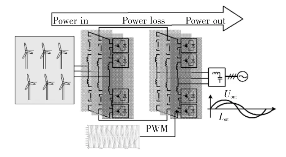
图1 应用于海上风电传输的MMC变流器系统Fig.1 Wind power transmission system with MMC
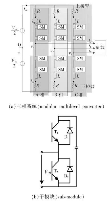
图2 MMC变流器系统子模块与结构Fig.2 Structure of modular multilevel converter(MMC)and sub-module
1 Power Loss Analysis
To illustrate the lifetime estimation procedure, an offshore wind power generation HVDC transmission system shown in Fig.1 is chosen as a study case, and 9 wind turbines with 2 MW rated power each are composed as an offshore wind farm.Both the generator-side converter and the grid-side converter employ the three-phase MMC,which is detailed in Fig.2,it can be seen that each phase of the MMC has twoarms being composed of N sub-modules and a series connected inductor.These sub-modules are identical and generally configured in half-bridge.Each submodule consists of two insulated-gate bipolar transistors(IGBTs)T1,T2and two antiparallel connected diodes D1,D2,as well as an energy storage capacitor C.The Infineon IGBT module FZ750R65KE3(Tj=150℃)is chosen as power semiconductor devices.The system specifications are basically designed according to Tab.1.
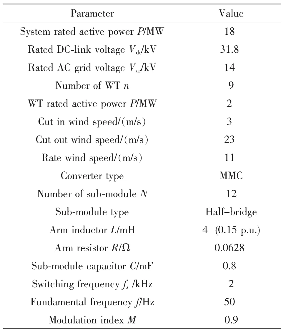
表1 本文MMC网测变流器系统主要参数Tab.1 Specifications of the MMC system
As the generator-side converter can share a similar analysis approach with the grid-side converter,for simplicity only the latter is analyzed in this paper.A phase shift carrier pulse width modulation(PSCPWM)scheme[13]is applied and its output line-to-line voltages vab,vbc,vcaare shown in Fig.3.The distortion of the output voltage is caused by the charging and discharging of the capacitors in sub-modules.The output current iaand arm currents ia1,ia2in phase A are displayed in Fig.4.The distortion of the arm currents is caused by the dc components and ac components in the zero sequence current.
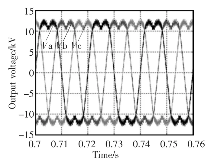
图3 网侧MMC变流器的参考输出电压Fig.3 Output voltage of the grid-side converter with MMC
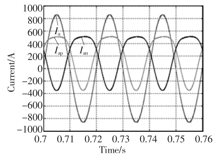
图4 网侧MMC变流器A相输出电流以及桥臂电流Fig.4 Output current and arm currents in phase A of the grid-side converter with MMC
There are several types of grid faults in such system and three typical grid faults are defined and explained in[14],single-phase ground fault,two-phase connected fault and three-phase ground fault.However, no matter which type it is,when a short-circuit fault happens in the power grid system,normally,the voltage dips will be detected by the grid-connected converter through the ac bus it is connected(PCC),and then the corresponding LVRT control algorithm of the WTS is activated,making the converter shift from the normal operation mode to the LVRT mode.In this paper,only single-phase ground fault in phase A is focused on[15,16].
Different from the traditional two-level or three-level converters,the power calculation of MMC is much more complicated.Therefore,the MMC working principle along with its power loss calculation is introduced.
The working principle of the sub-module in MMC can be divided into four stages depending on the gate signal of each device g(gT1,gT2,gD1,gD2denoting the gate signal of upper IGBT,lower IGBT,upper Diode and lower Diode,respectively)and the current direction ikp(n)(k=a,b,c,p=upper arm,n=lower arm).As shown in Fig.5,the following can be obtained for the operation:
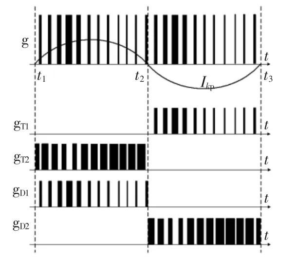
图5 A相子模块的PWM调制信号Fig.5 PWM pattern for sub-modules in phase A
(1)From t1to t2,the arm current ikpis positive,if T1is turned on,T2is turned off,the current flows through D1and C,the capacitor is charged as illustrated in Fig.6(a)and PSM=PD1;otherwise,T1is turned off,T2is turned on,the current will go through T2(Fig.6(b))and PSM=PT2;
(2)In the next stage from t2to t3,the arm current ikpis negative,when T1is turned off,T2is turned on,the current flows through D2(Fig.6(c)),PSM=PD2; oppositely,when T1is on,T2is off,the current will go through T1and C,the capacitor is discharged as shown in Fig.6(d),PSM=PT1.

图6 MMC变流器系统子模块的4个工作模式Fig.6 Four working stages of the sub-module in the MMC
Where PSMis the power loss of the sub-module,is the loss of D1,T2,D2,T1respectively.This can be represented as shown in Tab.2 and the simulation results are shown in Fig.7 which is obtained under the rated wind speed.
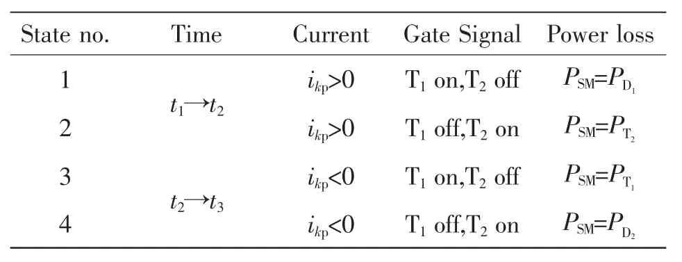
表2 MMC变流器系统子模块的4个工作模式Tab.2 Four working regions of sub-module in MMC
In Fig.7,the upper arm current(Iap),the gating signal for the upper IGBT(Gap),the capacitor voltage and current(Vcand Ic),the currents flowing through the four semiconductors in the first module in upper armis shown.As can be seen in Fig.7,when the arm current iapis positive,the current go through D1,T2and when the arm current iapis negative,the current flow through,D2,T1depending onthe status of the gating signal Gap.The results agree with the definition in Tab.2.
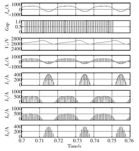
图7 MMC变流器系统额定工作状态下的器件电流应力Fig.7 Simulation results of working principle of MMC
The power losses of the semiconductors in one sub-module in phase A under the rated wind speed are given in Fig.8 by employing the power loss model which shares the same idea as that in[17].From Fig.8, the semiconductors in the same module consume different power losses and the T2occupies the most,followed by T1and D1orderly and D2has the smallest power loss.The unbalanced power loss is caused by the distortion of the arm current due to the zero sequence component in the arm current,especially the dc component which makes the positive arm current lasting much longer time than the negative arm current in each fundamental period.Therefore,according to the above analysis,the D1and T2work longer time than D2and T1and thereby consume more energy.

图8 MMC变流器系统A相子模块额定工作状态下的器件实时损耗Fig.8 Power loss of the devices in the first SM in phase A
Fig.9 gives the operation profile in German grid codesforthe MMC outputsundersingle-phase ground fault in phase A with the grid voltage dip severity denoted as Dip=0.5 p.u..The output voltages, load currents,and the instantaneous active/reactive power values are shown,respectively.As it is shown in Fig.9,the output voltages under the given grid fault condition are consistent with the fault definition, and the currents are symmetrical among the three phases,which means that only positive sequence currents are injected according to the low-voltage ridethrough(LVRT)codes for wind turbine systems(WTSs)issued by several countries[18].Due to the existence of negative sequence voltage,there is a second order frequency oscillation in the delivered active and reactive power values under the conditions of one-phase and two-phase unbalanced grid faults.
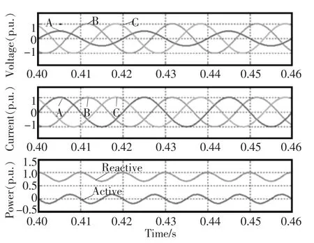
图9 在A相电网电压跌落时MMC变流器输出波形(电压跌落0.5 p.u.,风速vw=11 m/s)Fig.9 Outputs of the grid-side MMC under Singlephase ground fault in phase A(Dip=0.5 p.u.,vw=11 m/s,German grid code[18])
The averaged active power and reactive power delivered by MMC versus voltage dips under the single-phase ground fault in phase A are shown in Fig.10.It can be seen that the reactive power is significantly different,especially when Dip<0.5 p.u..
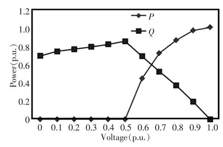
图10 A相电网电压跌落幅值下MMC变流器有功和无功(风速vw=11 m/s)Fig.10 Active and reactive power values versus dip severity on the PCC under single-phase ground fault in phase A(vw=11 m/s,German grid codes[18])
The loss distributions of the four power switching devices in the same module in each phase at different grid voltage dip severity values under the single-phase ground fault in phase A are indicated in Fig.11,in which the AT1,BT1,CT1mean T1in phaseare D1in phaseare T2in phase A,B,C andare D2in phase A,B,C.All of them are obtained under the rated wind speed vw=11 m/s.It can be seen that the loss distribution among the three phases of the converter are asymmetrical under the one-phase unbalanced grid fault.Moreover,the most stress is imposed to T2,which is different from the normal condition.
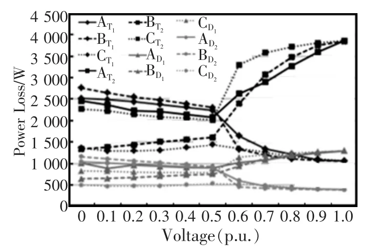
图11 各种单相电网电压跌落幅值下MMC变流器器件损耗(风速vw=11 m/s)Fig.11 Power loss versus grid voltage dip severity under single-phase ground fault in phase A(vw=11 m/s,German grid codes[18])
2 Thermal Distribution of Power Device
The thermal distribution of the MMC can be obtained based on the power loss calculated above and the dynamic electro-thermal model denoted by the thermal equivalent circuit diagrams in Fig.12.
In Fig.12,TJIGBTand TJDiodeare junction temperatures of IGBT and Diode,respectively;TCcase temperature;THheatsink temperature;TAambient temperature;Zththe impedances from junction to ambient;ZthJC,the impedances from junction to case;ZthCHthe impedances from case to heatsink;ZthHAthe impedances from heatsink to ambient.Both ZthTJCand ZthDJCare composed of the equivalent thermal resistance and capacitance networks,generally described by Foster and Cauer[19].Equivalent impedance can be obtained from the datasheet.Thermal resistances Rican be directly read,whereas thermal capacitances Cican be computed from τi=RiCiwhich is given in datasheet.PLIGBTmeans the power loss in the UGBT, PLDiodemeans the power loss in the freewhecling diode.The junction temperature calculation can be expressed as

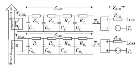
图12 功率半导体器件热力学模型Fig.12 Electro-thermal network of power semiconductor devices
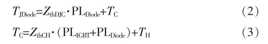
Here,a fourth-order Cauer model is employed as described in Tab.3 and RTH=0.009 K/W and RDH= 0.014 K/W.
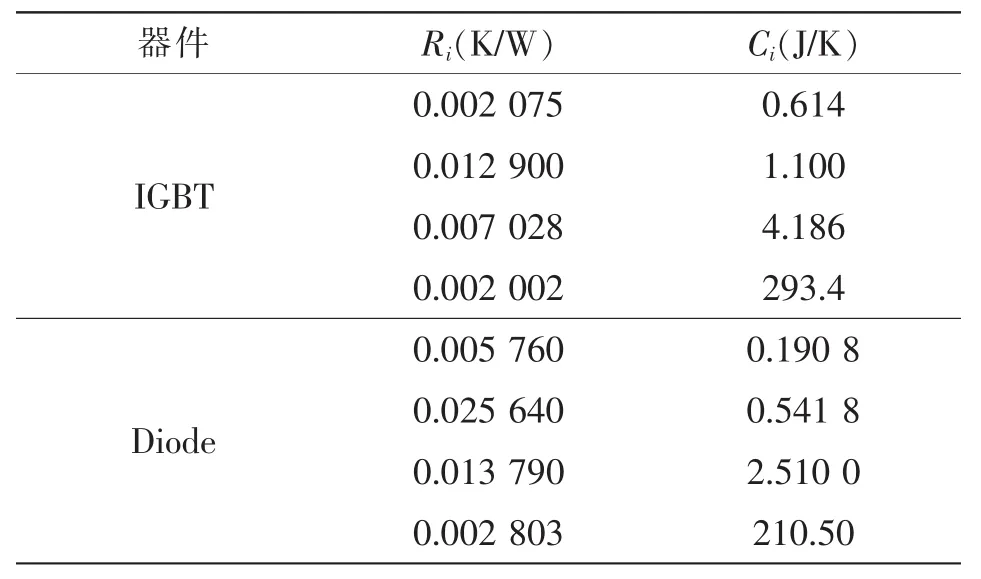
表3 功率器件4阶Cauer型热力学模型参数Tab.3 Specification of the fourth-order cauer model
Based on the previous loss results and the above thermal model,the junction temperature of the power devices under various grid faults can be investigated by PLECS blockset in Simulink.The thermal profiles under normal condition single-phase ground fault in phase A are shown in Fig.13 and Fig.14,respectively.


图13 MMC网测变流器在正常电网电压下子模块器件热应力(风速vw=11 m/s)Fig.13 Thermal distribution of the grid-side MMC under normal condition(vw=11 m/s)

图14 在单相电网电压跌落下MMC网测变流器子模块器件热应力(跌落幅值0 p.u.,风速vw=11 m/s)Fig.14 Thermal distribution of the grid-side MMC under single-phase ground fault(Dip=0 p.u.,vw=11 m/s)
Fig.13 displays the thermal distribution under normal condition in phase A,B and C,in which it can be seen that the operation is balanced among the three phases under normal condition.Moreover,no matter which phase,T2and D1are the most stressed in this situation.
The junction temperatures for the devices in the same module in the three phases of MMC undergoing single-phase grid fault are shown in Fig.14(a)~(c), respectively.It is shown that the thermal loading behaviors in the three phases of the converter are totally different from each other under this fault condition.In phase A,T1and T2are the most stressed,while in Phase B,T1and D2are more stressed and in phase C, T2and D1are the most stressed as compared to normal condition.
The junction temperatures of the switches and the diodes under different dip severity values of the one-phase grid fault are shown in Fig.15.It is noted that when Dip is below 0.5 p.u.,T1and T2have the higher temperatures in phase A,while in phase B,T1and D2have the higher temperatures and in phase C, the temperatures of T2and D1are higher than the other two.When Dip is above 0.5 p.u.,the temperatures in all three phases trend to the normal condition.
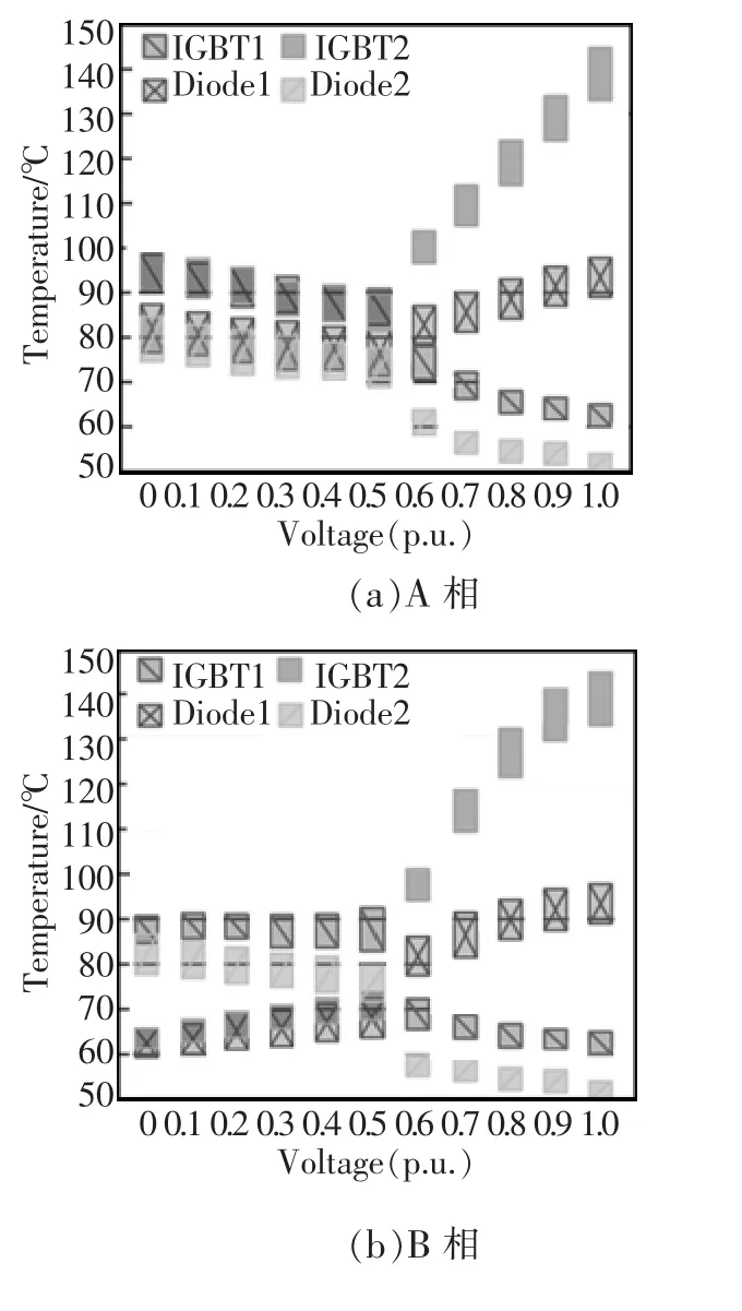
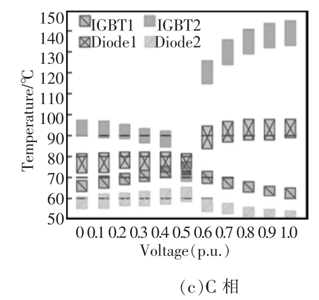
图15 在各种单相电网电压跌落下MMC网测变流器,子模块器件热应力(风速vw=11 m/s)Fig.15 Thermal distribution of the grid-side MMC under single-phase ground fault(vw=11 m/s)
4CONCLUSION
Because the loading conditions of power devices in the MMC under grid faults are still not yet clarified,this paper has focused on the investigation of influence of different mission profile and various grid voltage dips on the operating and loading behaviors of MMC.The analyzing methods and results are of importance for understanding and improving the thermal performance of the MMC under grid fault condition.
Depend to the types and severity values of grid faults,as well as LVRT control strategies,the operation status of the grid-connected MMC such as the output current,and the delivered power are significantly different.It is noticed that the operation conditions of the MMC are unsymmetrical among the three phases when unbalanced grid faults are present.
Both the grid faults and severity values of voltage dips will lead to unbalanced device loading among the three phases of MMC.It should be notedthat some power devices under the LVRT operation may have even higher junction temperature than the normal full load operation condition.This overloading should be taken into account when choosing the power devices and designing the heat sink system for the wind power converter.
[1]Marquardt R,Lesnicar A,Hildinger J.Modulares Stromrichterkonzept für Netzkupplungsanwendung bei hohen Spannungen,ETG-Fachtagung[C].BadNauheim,Germany,2002.
[2]Allebrod S,Hamerski R,Marquardt R.New transformerless, scalable modular multilevel converters for HVDC-transmission[C].in Proc.of PESC’2008,Rhodes,2008:174-179.
[3]Gnanarathna U N,Gole A M,Jayasinghe R P.Efficient Modeling of Modular Multilevel HVDC Converters(MMC)on Electromagnetic Transient Simulation Programs[J].IEEE Trans.onPowerDel.,2011,26(1):316-324.
[4]Saeedifard M,Iravani R.Dynamic performance of a modular multilevelback-to-back HVDC system[J].IEEE Trans.Power Del.,2010,25(4):2903-2912.
[5]Guan M Y,Xu Z.Modeling and vontrol of a modular multilevel converter-based HVDC system under unbalanced grid conditions[J].IEEE Trans.Power.Electron.,2012,27(12):4858-4867.
[6]Glinka M,Marquardt R.A New AC/AC Multilevel Converter Family[J].IEEETrans.Ind.Electron.,,2005,52(3):662-669.
[7]Yang S,Bryant A T,Mawby P A,et al.An industry-based survey of reliability in power electronic converters[J].IEEE Trans.Ind.2011,47(3):1441-1451.
[8]Due J,Munk-Nielsen S,Rasmus N.Lifetime investigation of high power IGBT modules[C].in Proc.of EPE’2011.Birmingham,2011:1-8.
[9]Ma K,Liserre M,Blaabjerg F,et al.Thermal loading and lifetime estimation for power device considering mission profile in wind power converter[J].IEEE Trans.Power Electron., 2015,30(2):590-602.
[10]HuangH,MawbyPA.Alifetimeestimationtechniqueforvoltagesourceinverters[J].IEEETrans.PowerElectron.,2012,28(8):4113-4119.
[11]IsidoriA,RossiFM,BlaabjergF,etal.Thermalloadingandreliabilityof10MWmultilevelwindpowerconverteratdifferent windroughnessclasses[J].IEEE Trans.Ind.Appl.,2013,50(1):484-494.
[12]Bina Y M T,Eskandari B.Efficiency of three-level neutralpoint clamped converters:analysis and experimental validation of power losses,thermal modelling and lifetime prediction[J].IEEE Power Electron.Lett.,2014,7(1)204-214.
[13]Zhang M,Huang L,YaoW X,et al.Circulating harmonic current elimination of a CPS-PWM-based modular multilevel converter with a plug-In repetitive controller[J].IEEE Trans.Power Electron.,2014,29(4):2083-2097.
[14]Ma K,Liserre M,Blaabjerg F.Operating and loading conditions of a three-level neutral-point-clamped wind power converter under various grid faults[J].IEEE Trans.Ind.Appl., 2014,50(1):520-530.
[15]Ma K,Blaabjerg F,Liserre M.Thermal analysis of multilevel grid side converters for 10 MW wind turbines under low voltage ride through[J].IEEE Trans.Ind.Appl.,2013, 49(2):909-921.
[16]Ma K,Blaabjerg F.Thermal optimized modulation method of threelevel NPC inverter for 10 MW wind turbines under low voltage ride through[J].IETJ.Power Electron.,2012,5(6):920-927.
[17]Blaabjerg F,Jaeger U,Munk-Nielsen S,et al.Power losses in PWM-VSI inverter using NPT or PT IGBT devices[J].IEEE Trans Power Electron,1995,10(3):358-360.
[18]Altin M,Goksu O,Teodorescu R,et al.Overview of recent grid codes for wind power integration[C].in Proc.OPTIM, 2010:1152-1160.
[19]Wintrich A,Nicolai U,Reimann T.Semikron Application Manual[S].2011:287.
Loading Analysis of Power Devcie in Modular Multilevel Converter Under Grid Faults
LIU Hui1,MA Ke2
(1.Department of Energy Technology,Aalborg University,Aalborg 9220,Denmark;2.school of Electronic Information and Electrical Engineering,Shanghai Jiao Tong University,Shanghai 200240,China)
Due to a series of merits,Modular Multilevel Converters(MMCs)have been developing dramatically in the last decade.However in some applications like offshore power transmission the MMC modules are subjected to a variety of tough mission profiles with adverse working conditions,all of these could lead to thermo-mechanical fatigues in the components and joints of the power modules and thereby causing reliability challenge to this converter.This study focuses on the loadin ganalysis of MMC considering the grid faults in the High Voltage Direct Current(HVDC)application for offshore wind power.The faulty conditions as well as the topology of the MMC are analyzed in order to better understand the loading characteristics of MMC.Then the power loss calculation along with the electro-thermal simulation is conducted to uncover the thermal loading behaviorsof MMC under various single-phase grid fault conditions.
modular multilevel converter(MMC);reliability;mission profile;low-voltage ride-through(LVRT)

刘慧
刘慧(1986-),女,博士,研究方向:电力电子可靠性,E-mail:hui@et.aau.dk。
马柯(1985-),男,博士,特别研究员,研究方向:电力电子可靠性提高及设计,可再生能源发电,E-mail:kema@sjtu.edu.cn。
10.13234/j.issn.2095-2805.2016.6.1
TM464
A
